
-

SUBSCRIBE TO SHIPS IN SCALE TODAY!
The beloved Ships in Scale Magazine is back and charting a new course for 2026!
Discover new skills, new techniques, and new inspirations in every issue.
NOTE THAT OUR NEXT ISSUE WILL BE July/August 2026 -

Win a Free Custom Engraved Brass Coin!!!
As a way to introduce our brass coins to the community, we will raffle off a free coin during the month of August. Follow link ABOVE for instructions for entering.
You are using an out of date browser. It may not display this or other websites correctly.
You should upgrade or use an alternative browser.
You should upgrade or use an alternative browser.
Cutty Sark, Vintage Billing Boats BB564, 1:75.
- Thread starter DomCee
- Start date
- Watchers 30
-
- Tags
- billing boats cutty sark

- Joined
- Sep 23, 2021
- Messages
- 343
- Points
- 238

Hi Nomad,You have been busy Dom! Very interesting 'sub-projects' indeed")
I think I was using the sub-projects as a distraction to working on the CS - it's such a big model and the amount of work that will need to go into it is daunting - and I have barely started! The build will be deliberately slow for the time being because I am hoping to go down to London in the spring to check out the 1:1 original so that I can take some detailed pictures (and have a nice day out) to work from and, I don't want to get too far ahead of myself before I do that.
You are making excellent progress on HMS fly. The decking and second planking looks top notch!
Dom

Hallo @DomCeeI will not be starting my next build for a while but I thought I would give it a “heads up” now that I have the kit in the shipyard.
Part 1 - Start of a Long Voyage
Choice of Kit - an Odd (or Familiar) Story?
The windjammers/clippers from the mid to late 19th century have always fascinated me for their sleek hull lines and sheer amount of sail. The Cutty Sark is a classic model to build of this type and there are a number of kits to choose from. I looked at some reviews and builds of Cutty Sark kits on the SOS forums and other web sites. Robertd’s recent build of the Sergal/Mantua kit < R'Ds CS > came out very nicely. I was intending to buy that kit later this year but I spotted an estate clearance auction listing for an “old” model boat kit of the Cutty Sark. It turned out to be Billing Boats BB564 complete with the separate fittings kit that had been purchased as a “project” but never started. I left a silly low commission bid and to my surprise won the auction. When I received it I found that it was still in its original shipping box and wrapping paper and had only been opened for inspection. The kit itself is in near mint condition, just some slight damage to the box where the sealing tape had been. The fittings box ( that you had to purchase separately back then) was unopened.
View attachment 323980
Judging from the postage labels the kit was bought in the mid 80’s and has spent the past 37+ years languishing at the back of a cupboard (it makes me wonder just how many model kits have been bought with good intentions but are now just collecting dust?).
I think that it is time for this Cutty Sark to see the light of day and spread her sails (probably not the Stuns’ls!).
Gathering My Thoughts on a Build Plan
Although it is not my first choice of kit it will be a good challenge (but I may also regret this one). It will also be the biggest model I have attempted. The completed model is 1.1m (43”) long and the desk I use for my hobby work is 1.4m wide so I am going to struggle (I also have no idea where I will put it when it’s done!). I am also sure that the rigging will test my patience (and my eyesight!) to the limit but that stage is a long way off into the future for now. I don’t have a lot of space to display my models so it is my intention to take my time over this build, add extra detail and make more parts from scratch. I think I will also need plenty of advice on building this one!
The kit is definitely “vintage” (no laser cut parts). I know that Billing kits from this time were not of the best quality but I will be using this as a base kit for the model build so I’m quite OK with the out-of-the-box quality issues from the day. All of the frames are jig cut and some of the ply parts are die-cut. Other detailing parts are just printed onto ply sheets and need to be cut out (I will probably just use them as templates and make new parts from solid wood). The decorative mouldings and service boats are plastic as are the rigging blocks and deadeyes. The rear transom decoration is a decal. The instructions are the usual basic ones from BB with four plan drawings of layout, sails, pins and rigging.
View attachment 323977View attachment 323978View attachment 323979View attachment 323981
Because I paid very little for the kit I will upgrade it as I go through the build by replacing all of the plastic parts with wood/brass and making new parts where I think the model will benefit.
I have already purchased a set of photo-etched decor parts and a full set of walnut CNC rigging blocks from HisModel. The rigging blocks came in two sets, one for the standing rigging (224 pieces) and one for the running rigging (535 pieces). The blocks are of the correct type and size for this model (759 blocks to rig is however very intimidating!).
I will replace the plastic service boats with wooden ones of the correct type and scale. If anyone knows where I can find some suitable 1:75 kit replacements (or some scale plans so that I could make them myself) that would be great, please let me know through the forum.
I will also replace the rigging thread with some decent rope when I reach that point (I think I will purchase rather than try to make my own).
The BB kit has no hull plates included and the lower hull is suggested to be painted (I think even the latest version of this kit does not offer plates as an option). I would like to sheath the hull because the real ship was sheathed and I will consider options for that upgrade when I reach that point.
To help with the build and rigging I have bought a set of G.F. Campbell’s plans (General Layout, Rigging and Sail Plan) from the Royal Museums Greenwich. I also found Olha’s book review “Cutty Sark, The Ship and the Model/Longridge. C Nepean'' on her YouTube Channel < CS ref book > and I was able to locate a good used copy of the book in the UK. I do not intend to go the “whole hog” on the model by super-detailing it, my intention is to improve it to a level that I am happy with (whatever that is?).
View attachment 323983View attachment 323982View attachment 323984View attachment 323985
I will take a long holiday soon and I have some home improvement projects to do when I return, so it will be a while before I can get started on the framing (probably late autumn). Now that the pandemic is over (I hope!) I have many other things to do, so I will have less time to spend on the ship hobby. I will mainly work on this model during the winter weather months and I will intersperse the work between projects. I am expecting that I will be working on this one for quite some time to come (?years?!) but I am in no hurry.
I will give an update once I have kicked-off the framing.
we wish you all the BEST and a HAPPY BIRTHDAY

- Joined
- Sep 23, 2021
- Messages
- 343
- Points
- 238
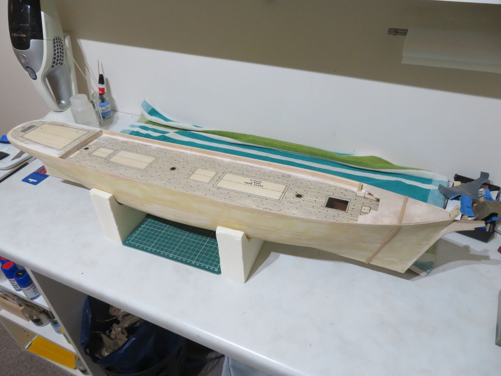
Part 5 - Some Hull Work - Glacial Progress
Not much has been done on the ship for a while but I found some time to get back into the shipyard so I blitzed through some planking in order to make some progress on the hull.
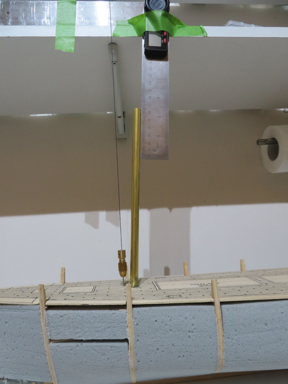
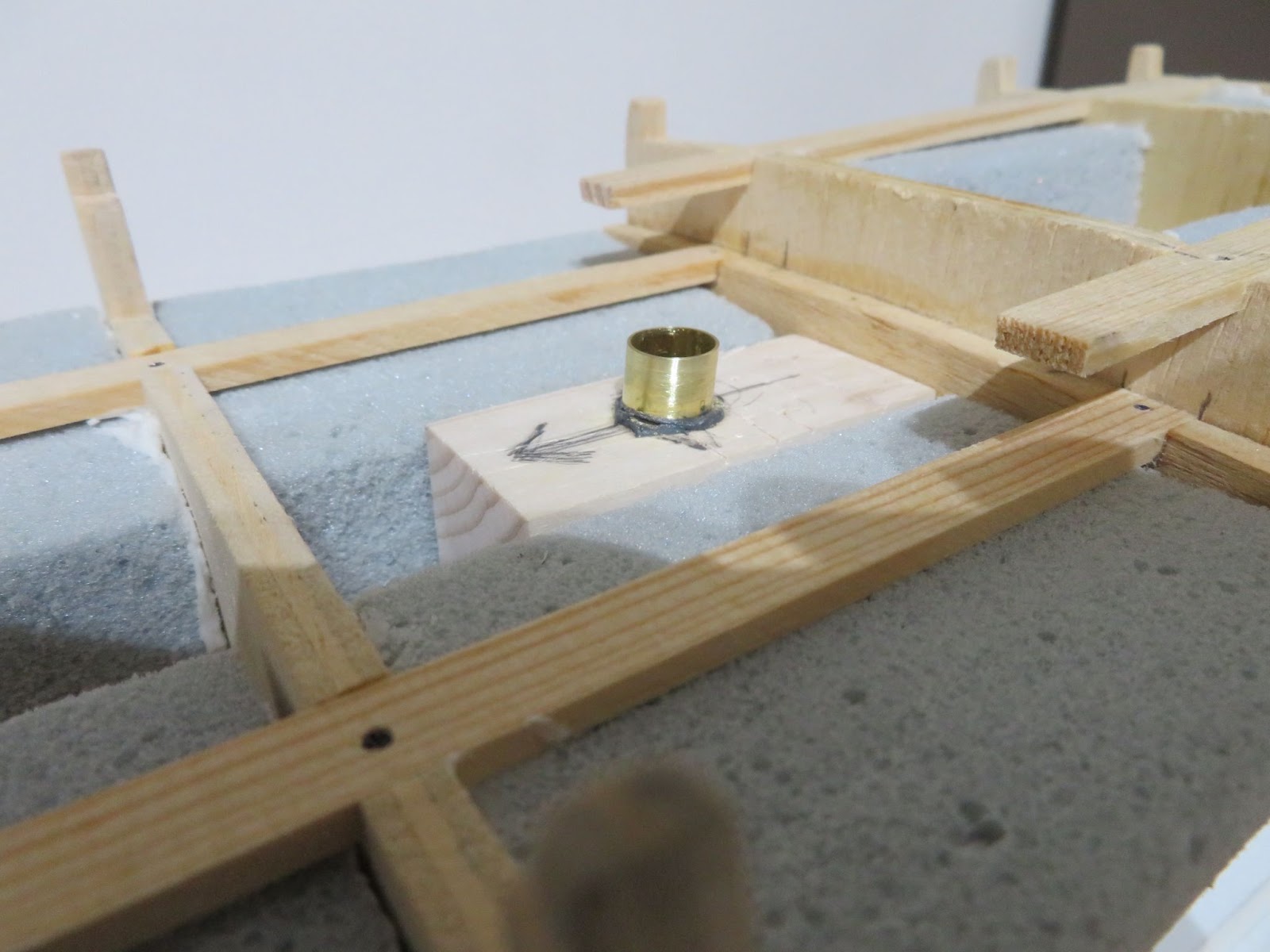
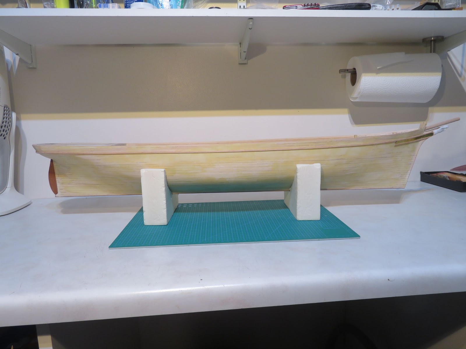
Before putting some planks on the hull, I realised that it would not be an easy task to set the mast rakes later in the build because trying to drill out the lower mast supports at the correct angles will risk damaging the hull and decking. For the CS the fore, main and mizzen masts are raked back at 86°, 85° and 84° respectively (from the keel). The frames in the kit do not give any good positional support to the masts so to get the angles correct I decided to fit brass tube housings into the hull which I could slide the masts into later. I drilled out some wooden blocks at the correct angles and then used some epoxy to fix the tubes into the blocks. It was then straightforward to position the blocks in the hull with some slow-cure epoxy so that I had plenty of time to make any adjustments. I taped my divider to a shelf and hung a plumb-bob so that I could check that the rake was correct for each mast and to make sure that the masts were perpendicular to the deck. I cut off the brass tube at the deck level once the glue had set.
With the lower mast supports done I fixed the false deck down in place and started on planking the lower hull.
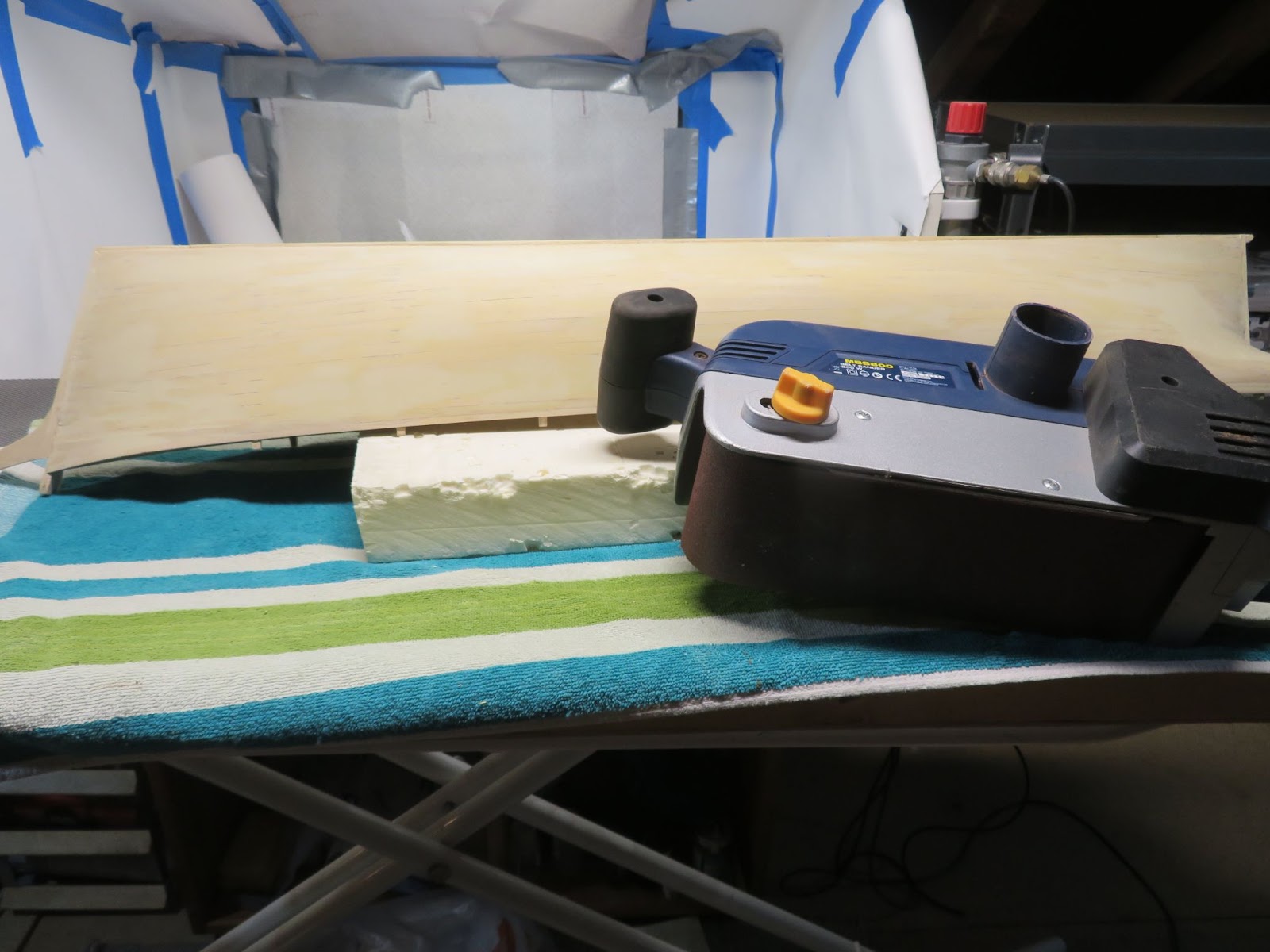
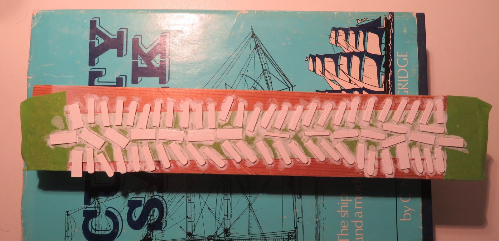
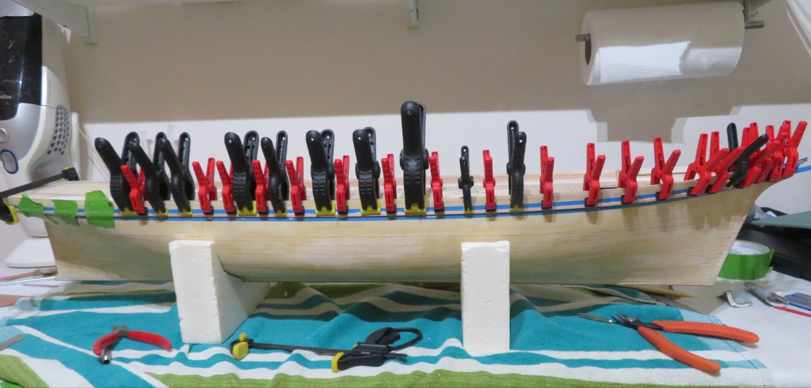
I managed to get the lower hull planked without “too much” bad language being uttered but I made a rod for my back by not measuring off the hull properly. I decided to plank down from the deck level and because the hull is fairly “slab-sided” I started with full width planks with the intention of measuring off the remaining hull once I had placed a few planks. The planking “was” going OK but then rapidly turned south. Following the deck level was a mistake because I did not allow for the fact that the deck sweeps up slightly to the bow so as I planked down I started to get into a bit of a mess. I should have divided off the hull with some stringers first (which is the correct way to do it) and that would have saved me a lot of hassle (lesson learned!). However, I was able to correct matters by placing two planks up from the keel and measuring off the remaining open hull at each frame and dividing each measurement by a whole number of planks at the widest part. I then trimmed the remaining planks and made any corrections as I went in order to close up the hull. The planks that came with the kit are 7 mm wide so getting full length planks to follow the hull line and sit squarely on the frames especially where they curve in to meet the stern post was a bit of a task. I think it would have been easier to have used either 4 or 5 mm planks (or both) but in the end it was OK. I did find that the use of the PU foam filler was really helpful because I was able to use long push pins (actually plastic headed upholstery tacks) which held really firmly into the foam so I could hold the planks in place without using any nails. Once the glue cured I could just pull out the pins - very easy - no split planks. It was not my best effort but I will be painting and sheathing the hull so I will be spending a good deal of time refining the shape and any errors will magically disappear under some wood filler!

I will work on the upper bulwarks and counter stern next but the true construction of the bulwarks is very different to that shown in the plans (the model is a very simplified version with planking up to the top rail and the main rail fixed to the stanchions and the inner bulwarks). The upper bulwark construction is actually quite complicated on the CS. The pictures show the bulwarks inner and outer construction and consists of iron plates, main rail, top rail and A-frame supports. The plates also have hinged clearing ports set in them and the Billing plans show four clearing ports (per side) but there are no pieces in the kit and there should be six so I will need to make some. The lower section of the bulwarks are the iron plates and the main rail sits on top of those supported by the frames and goes to the outer side of the hull forming a strake. The upper section sits on top of the main rail with short supports for the top rail and shaped inserts between the supports.

On the model the false stanchions support the main rail but they are rather clumsy looking so I have decided that I will remove them and I will make a set of frames from brass rod (26 per side). I will make a pair of new main rails which will sit on top of the lower bulwarks (as they should) which will look more authentic. I will also need to make the top rail structure with the supports and inserts.
Quite a lot to do so it might be a while before I can post another progress up-date. I also do not want to go too much further with the build because I am still hoping to visit the 1:1 original soon so that I can make a proper set of reference images to work from. Having some decent reference images will be very useful because I have found a lot of differences in the plans that I have (Cambell’s vs. Billings vs. Longridge’s vs. some plans I found from 1961 (ZNM?)).
Not much has been done on the ship for a while but I found some time to get back into the shipyard so I blitzed through some planking in order to make some progress on the hull.
Before putting some planks on the hull, I realised that it would not be an easy task to set the mast rakes later in the build because trying to drill out the lower mast supports at the correct angles will risk damaging the hull and decking. For the CS the fore, main and mizzen masts are raked back at 86°, 85° and 84° respectively (from the keel). The frames in the kit do not give any good positional support to the masts so to get the angles correct I decided to fit brass tube housings into the hull which I could slide the masts into later. I drilled out some wooden blocks at the correct angles and then used some epoxy to fix the tubes into the blocks. It was then straightforward to position the blocks in the hull with some slow-cure epoxy so that I had plenty of time to make any adjustments. I taped my divider to a shelf and hung a plumb-bob so that I could check that the rake was correct for each mast and to make sure that the masts were perpendicular to the deck. I cut off the brass tube at the deck level once the glue had set.
With the lower mast supports done I fixed the false deck down in place and started on planking the lower hull.
I managed to get the lower hull planked without “too much” bad language being uttered but I made a rod for my back by not measuring off the hull properly. I decided to plank down from the deck level and because the hull is fairly “slab-sided” I started with full width planks with the intention of measuring off the remaining hull once I had placed a few planks. The planking “was” going OK but then rapidly turned south. Following the deck level was a mistake because I did not allow for the fact that the deck sweeps up slightly to the bow so as I planked down I started to get into a bit of a mess. I should have divided off the hull with some stringers first (which is the correct way to do it) and that would have saved me a lot of hassle (lesson learned!). However, I was able to correct matters by placing two planks up from the keel and measuring off the remaining open hull at each frame and dividing each measurement by a whole number of planks at the widest part. I then trimmed the remaining planks and made any corrections as I went in order to close up the hull. The planks that came with the kit are 7 mm wide so getting full length planks to follow the hull line and sit squarely on the frames especially where they curve in to meet the stern post was a bit of a task. I think it would have been easier to have used either 4 or 5 mm planks (or both) but in the end it was OK. I did find that the use of the PU foam filler was really helpful because I was able to use long push pins (actually plastic headed upholstery tacks) which held really firmly into the foam so I could hold the planks in place without using any nails. Once the glue cured I could just pull out the pins - very easy - no split planks. It was not my best effort but I will be painting and sheathing the hull so I will be spending a good deal of time refining the shape and any errors will magically disappear under some wood filler!
I will work on the upper bulwarks and counter stern next but the true construction of the bulwarks is very different to that shown in the plans (the model is a very simplified version with planking up to the top rail and the main rail fixed to the stanchions and the inner bulwarks). The upper bulwark construction is actually quite complicated on the CS. The pictures show the bulwarks inner and outer construction and consists of iron plates, main rail, top rail and A-frame supports. The plates also have hinged clearing ports set in them and the Billing plans show four clearing ports (per side) but there are no pieces in the kit and there should be six so I will need to make some. The lower section of the bulwarks are the iron plates and the main rail sits on top of those supported by the frames and goes to the outer side of the hull forming a strake. The upper section sits on top of the main rail with short supports for the top rail and shaped inserts between the supports.
On the model the false stanchions support the main rail but they are rather clumsy looking so I have decided that I will remove them and I will make a set of frames from brass rod (26 per side). I will make a pair of new main rails which will sit on top of the lower bulwarks (as they should) which will look more authentic. I will also need to make the top rail structure with the supports and inserts.
Quite a lot to do so it might be a while before I can post another progress up-date. I also do not want to go too much further with the build because I am still hoping to visit the 1:1 original soon so that I can make a proper set of reference images to work from. Having some decent reference images will be very useful because I have found a lot of differences in the plans that I have (Cambell’s vs. Billings vs. Longridge’s vs. some plans I found from 1961 (ZNM?)).
Great work Dom, I especially enjoyed the way you raked the masts!I taped my divider to a shelf and hung a plumb-bob so that I could check that the rake was correct for each mast and to make sure that the masts were perpendicular to the deck.
- Joined
- Sep 23, 2021
- Messages
- 343
- Points
- 238
Part 6 - Bulwarks, Counter-Stern, Shaping/Sanding the Hull.
A very frustrating past couple of months, I had to put the ship on “hold” because I have been so busy. I am sure a lot of fellow modellers have the same problem of “other-stuff-that-gets-in-the-way-that-you-have-to-do-to-pay-the-bills”.
However, the ship has been languishing in the shipyard for a bit too long so to move the build on I have done some more work on the hull. I do not like doing the model this way, I think slow and steady is more rewarding and maintains the flow - but needs must!
Constructing the bulwarks:- Rather than following the BB instructions I referred to the information given in Longridge’s book and the plans from Campbell. The main rails should sit on top of the bulwarks and run the length of the ship from the Fo’c’sle and meet the poop deck at the same level. The height of the bulwarks above the deck therefore has to be spot-on in order that the rail outers form continuous strakes along the hull. The rail is also the top section of the decoration at the bow and sandwiches the stern decoration with the lower hull band. Because the bulwarks sweep up to meet the knightshead at the bowsprit and the poop deck rises up slightly at the stern I decided to set the height using a planking strip. I measured and marked off the stanchions to give me the correct height above the deck and set 4mm strips the full length of the hull. I then planked down to meet the lower hull planking. I used some masking tape on the false stanchions to stop the strips from sticking to them so that I can cut them out later. The stanchions at the bow will support the fo’c’sle deck and will be hidden so I will leave them. I will clean up the inner bulwarks prior to painting but I think I will cover them with veneer strips first.

Counter- (pain-in-the) stern:-
I filled the stern spaces with some scrap wood, partially shaped it and then I tried attaching some wood strips - but it did not look very good. After a couple of tries I had a rethink and removed my previous efforts and pasted a 3mm strip around the rear of the poop deck so that I had an edge to work to. I glued some small tabs of strip to the filler blocks to give me the depth to shape the stern to, in-filled around the tabs with 2-part wood filler and then sanded to the correct profile. It is “about right” but I will need to tidy it up when I fit the lower hull band in order to make sure that the decorative brass work sits neatly between the band and the upper deck.
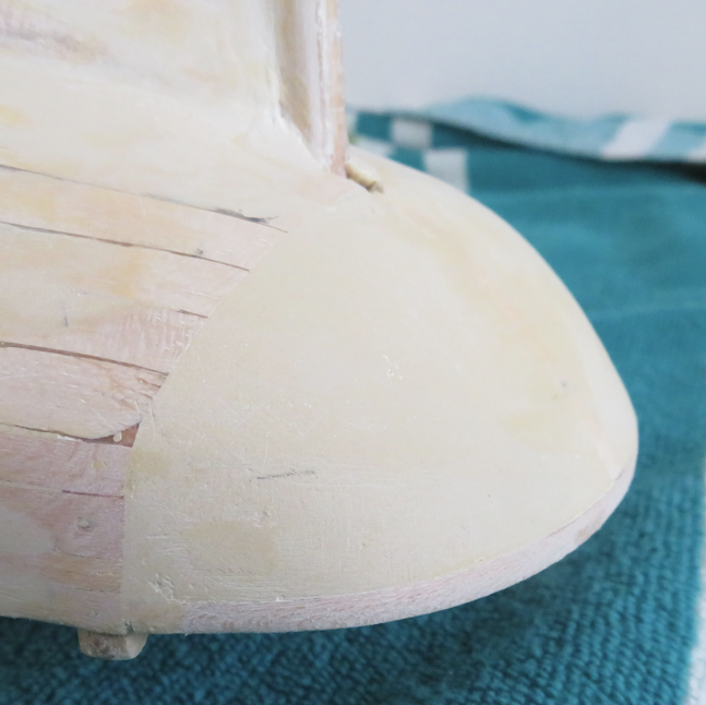
Sanding the hull:- With the counter-stern in place I went over the hull with some coarse grit and corrected any bad spots. The problem with this kit (and is the same for the current BB kit) is that the bulkhead spacings are far too large. Even after filling in the spaces there were a few areas of the hull that needed remedial work. Extra bulkheads would have certainly helped at the bow and stern, especially where the planks curve up to meet the counter stern (Billing + vintage = what I expected!). It took a few rounds of filling and sanding - filling and sanding - filling and sanding - filling and sanding - sanding, sanding (ad infinitum!) to shape the hull and smooth everything down. Before I start painting I will go over the hull again with some fine grit and fill in any minor blemishes.
Really?
There was some inevitable damage to the keel caused by bumps and knocks and catching it with the coarse grit so I ran my plane down it and pasted on a strip of hardwood with some thin strips along the sides in order to square it up again.
Prior to planking I glued some temporary strips on the bow and the stern post to give me an edge to plank to. I knew they would be damaged during the sanding process so they were just tacked in place and easily removed. I pasted on some new pieces and filled any gaps. An interesting little detail to note is that on the actual ship the bottom planks flare out to the width of the keel rather than being profiled into it.

Well, at least it’s a bit of progress!


The “big” decision that is now looming (can’t put it off for much longer!) is how I am going to sheath the hull. I definitely want to do it in brass as on the real ship but how I will do it is still up-in-the-air (under-the-water to be more precise). My first efforts at making plates did not go well (rubbish!) but I have since had a rethink and I am working on another approach that seems to be a bit more promising. Hopefully it will work out - time will tell - I will post an up-date when I can.
While I am procrastinating about the sheathing there are a few things I can get on with - rudder, main rails and hull band. I can also remove the false stanchions and tidy up the deck ready for planking.
A very frustrating past couple of months, I had to put the ship on “hold” because I have been so busy. I am sure a lot of fellow modellers have the same problem of “other-stuff-that-gets-in-the-way-that-you-have-to-do-to-pay-the-bills”.
However, the ship has been languishing in the shipyard for a bit too long so to move the build on I have done some more work on the hull. I do not like doing the model this way, I think slow and steady is more rewarding and maintains the flow - but needs must!
Constructing the bulwarks:- Rather than following the BB instructions I referred to the information given in Longridge’s book and the plans from Campbell. The main rails should sit on top of the bulwarks and run the length of the ship from the Fo’c’sle and meet the poop deck at the same level. The height of the bulwarks above the deck therefore has to be spot-on in order that the rail outers form continuous strakes along the hull. The rail is also the top section of the decoration at the bow and sandwiches the stern decoration with the lower hull band. Because the bulwarks sweep up to meet the knightshead at the bowsprit and the poop deck rises up slightly at the stern I decided to set the height using a planking strip. I measured and marked off the stanchions to give me the correct height above the deck and set 4mm strips the full length of the hull. I then planked down to meet the lower hull planking. I used some masking tape on the false stanchions to stop the strips from sticking to them so that I can cut them out later. The stanchions at the bow will support the fo’c’sle deck and will be hidden so I will leave them. I will clean up the inner bulwarks prior to painting but I think I will cover them with veneer strips first.
Counter- (pain-in-the) stern:-
I filled the stern spaces with some scrap wood, partially shaped it and then I tried attaching some wood strips - but it did not look very good. After a couple of tries I had a rethink and removed my previous efforts and pasted a 3mm strip around the rear of the poop deck so that I had an edge to work to. I glued some small tabs of strip to the filler blocks to give me the depth to shape the stern to, in-filled around the tabs with 2-part wood filler and then sanded to the correct profile. It is “about right” but I will need to tidy it up when I fit the lower hull band in order to make sure that the decorative brass work sits neatly between the band and the upper deck.
Sanding the hull:- With the counter-stern in place I went over the hull with some coarse grit and corrected any bad spots. The problem with this kit (and is the same for the current BB kit) is that the bulkhead spacings are far too large. Even after filling in the spaces there were a few areas of the hull that needed remedial work. Extra bulkheads would have certainly helped at the bow and stern, especially where the planks curve up to meet the counter stern (Billing + vintage = what I expected!). It took a few rounds of filling and sanding - filling and sanding - filling and sanding - filling and sanding - sanding, sanding (ad infinitum!) to shape the hull and smooth everything down. Before I start painting I will go over the hull again with some fine grit and fill in any minor blemishes.
Really?
There was some inevitable damage to the keel caused by bumps and knocks and catching it with the coarse grit so I ran my plane down it and pasted on a strip of hardwood with some thin strips along the sides in order to square it up again.
Prior to planking I glued some temporary strips on the bow and the stern post to give me an edge to plank to. I knew they would be damaged during the sanding process so they were just tacked in place and easily removed. I pasted on some new pieces and filled any gaps. An interesting little detail to note is that on the actual ship the bottom planks flare out to the width of the keel rather than being profiled into it.
Well, at least it’s a bit of progress!
The “big” decision that is now looming (can’t put it off for much longer!) is how I am going to sheath the hull. I definitely want to do it in brass as on the real ship but how I will do it is still up-in-the-air (under-the-water to be more precise). My first efforts at making plates did not go well (rubbish!) but I have since had a rethink and I am working on another approach that seems to be a bit more promising. Hopefully it will work out - time will tell - I will post an up-date when I can.
While I am procrastinating about the sheathing there are a few things I can get on with - rudder, main rails and hull band. I can also remove the false stanchions and tidy up the deck ready for planking.
I was also looking once for the Muntz metal or also called Naval Brass, with which the Cutty Sark is / was sheated
- but I could not find some folio or very thin plates
So I guess you have to use brass instead .....
BTW: Your work is looking very good
- but I could not find some folio or very thin plates
So I guess you have to use brass instead .....
BTW: Your work is looking very good
- Joined
- Sep 23, 2021
- Messages
- 343
- Points
- 238
Part 7 In Need of Motivation! A Visit to the 1:1
It was always my plan to stretch this build out because of lack of space and other projects that I want to do. However, looking back over the past year, I have not dedicated as much time to the build as I intended and progress has been “glacial” at best. The summer was eaten up by various home/garden/other projects followed by a much needed holiday hiking in the Alps. Now that the Autumn weather has arrived in the UK and outside jobs are winding down I will hopefully have a bit more time on my hands for the model.

Up in the Italian Alps
Before doing any further work on the model, I decided that I needed a bit of “motivation” and headed down to Greenwich - something I have been trying to do for a long time.

Soooooo much rigging!
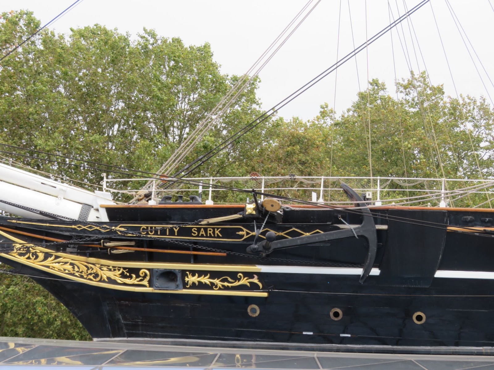
Apart from having a nice “motivational” day out, I made a detailed set of reference images for the build. Fortunately, the weather was quite kind to me and I was able to take lots of high res. photographs. I tried to capture as much detail as I could from the deck and from the wharfside - about 250 images. It would not be practical for me to up-load them all to the SOS site but if anyone needs images of a particular part of the ship please feel free to contact me through SOS and I will be very happy to check through and hopefully find something that will help.
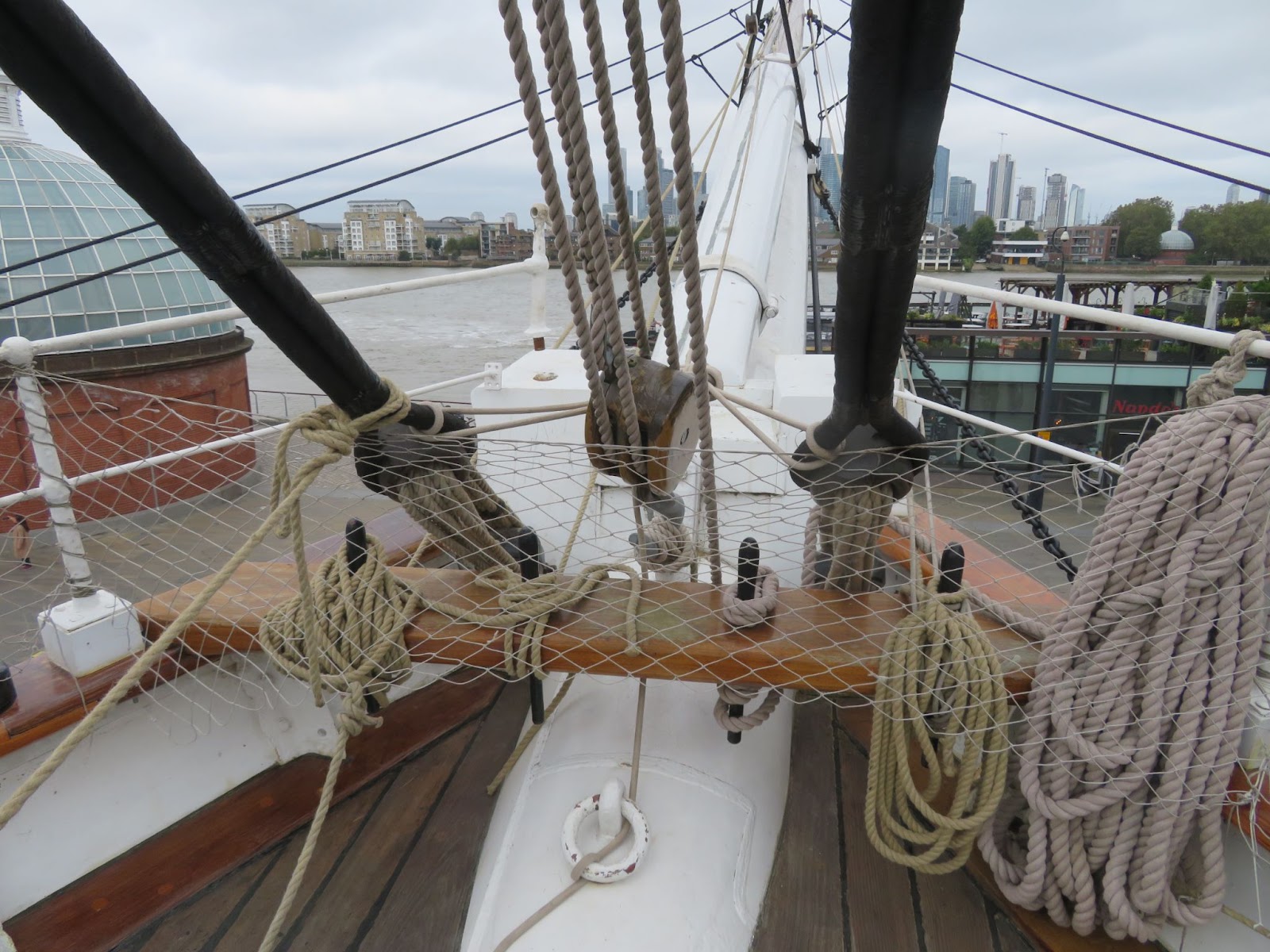
Details of the Knights Head
There was some conservation work in progress while I was there and access to the rear deck was not possible. I think some of the visitors were amused by the fact that I was going around with my measuring tape and placing a steel ruler by the fixtures and fittings (so that I could correctly scale the photographs at home) but the conservators immediately picked up on me and said “hi, making a model?”! I had a really good chat with them about the ship and they really appreciated it when I started to ask them specific questions about the construction and rigging. I learned quite a lot - turns out much of the 2006-12 restoration was botched and they are slowly putting things to rights. Really shameful considering they spent £50m ($81m) on the restoration - I think most of the money was spent on “consultants” - it would have been much cheaper to have built a brand new replica ship!
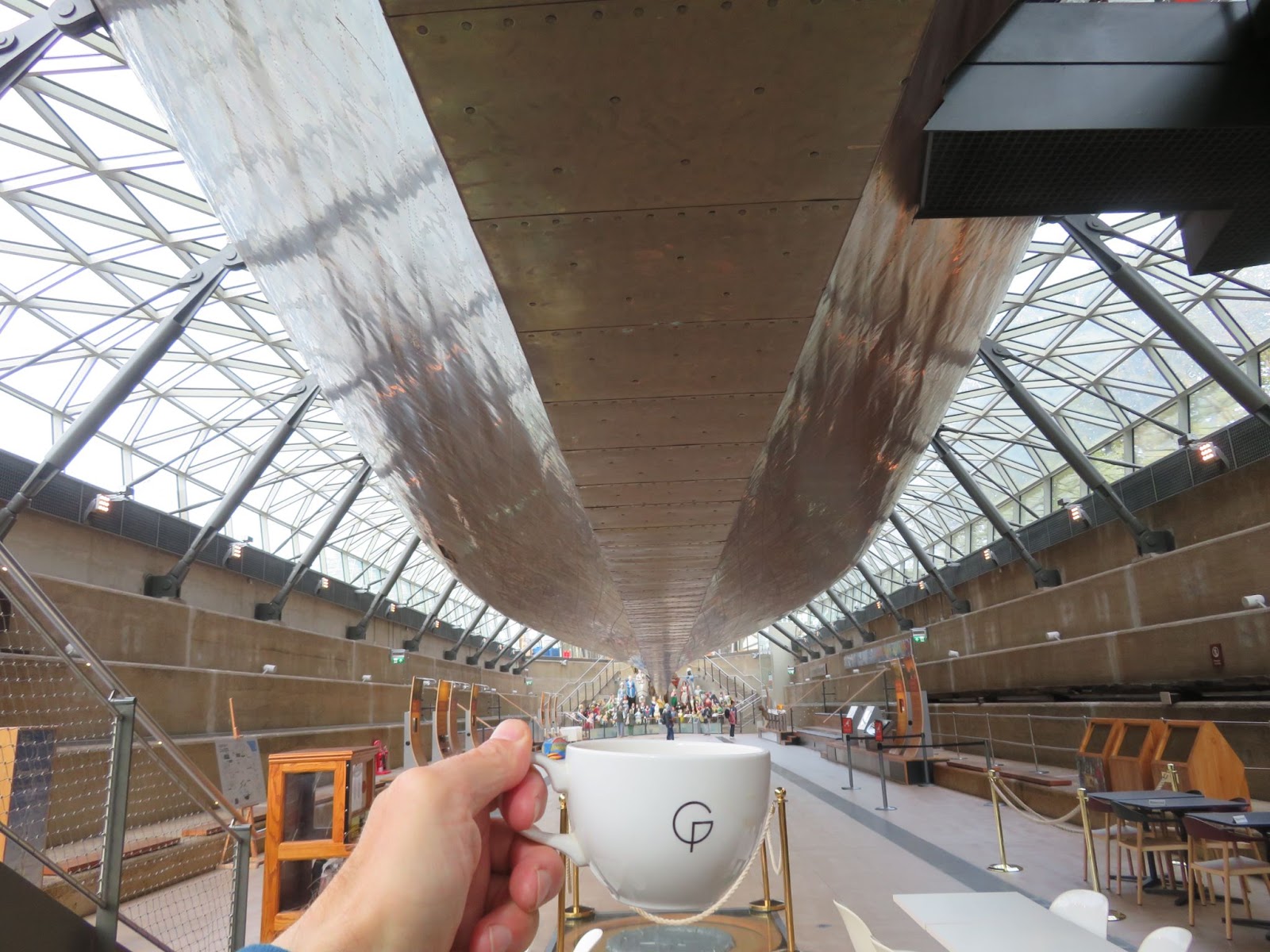
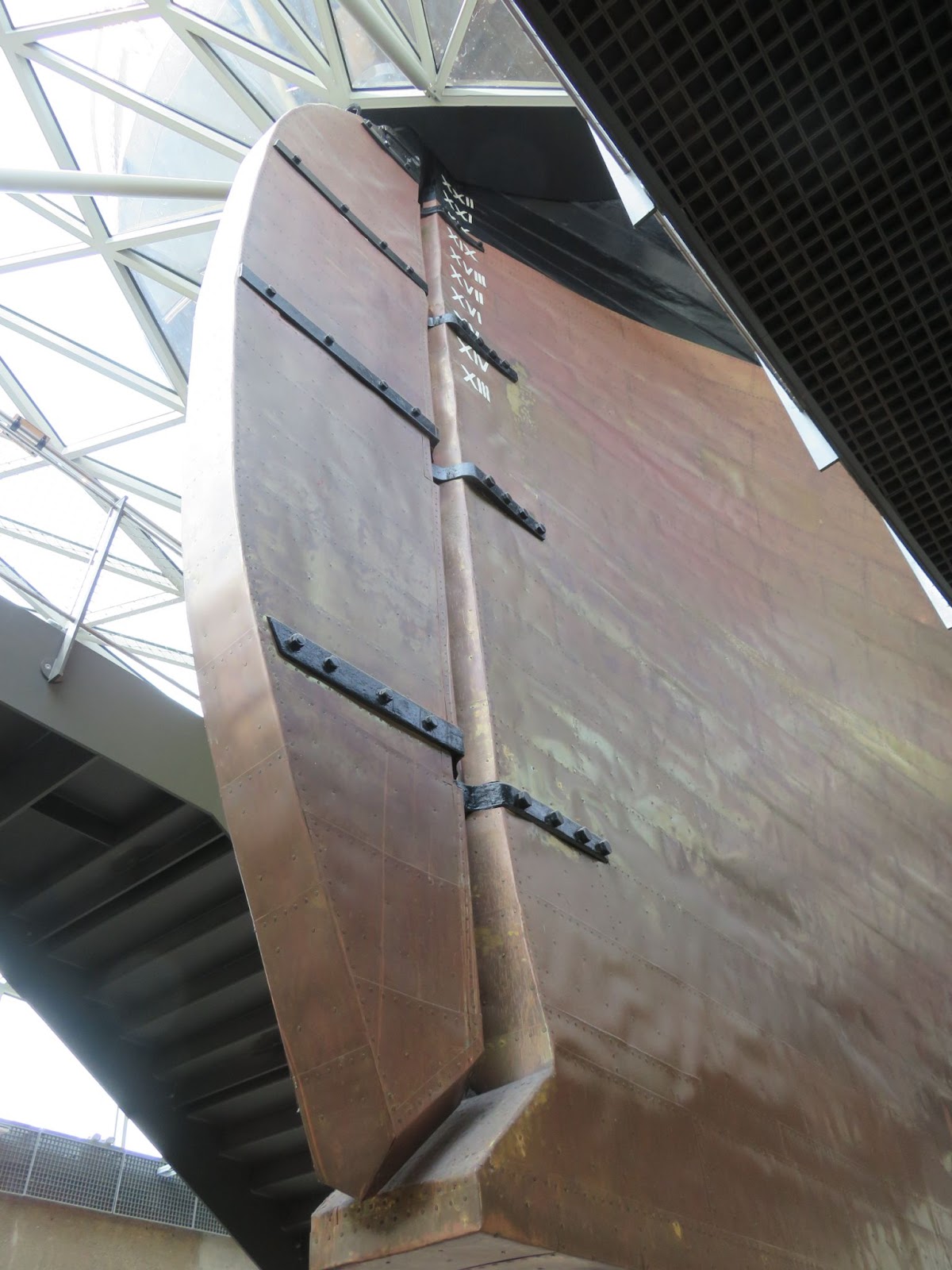
After my fairly thorough “survey” of the ship it was time to have a nice pot of tea whilst sitting under the hull (it’s a tea clipper - what else would I have?). I can only hope that my efforts to sheath the model in brass will look as good!
I also had time to visit the nearby Royal Maritime Museum. The galleries in the museum are now “themed” for visitors to discover and learn about periods of maritime history - all very interesting - but only a selection of the model collection is now on display, the models being chosen according to the theme. For modellers the best place to head to now is the Royal Dockyards Chatham where many famous naval sailing vessels were built. As well as undertaking research and conservation, a large part of the model collection is now housed there and they can be examined on request < The Historic Dockyard Chatham > . Unfortunately, Chatham is an additional 2.5 -3 hr round trip from the Cutty Sark and there is not enough time to travel between the sites and make a worthwhile visit to both museums in one day (I will perhaps make a special trip there sometime in the future).
Now that I have a much better connection to the Cutty Sark and a good set of reference images to work from, I am looking forward to getting on with the build again with renewed enthusiasm! Hopefully, I will be able to make some good progress over the next few weeks with some regular updates to the build log.
It was always my plan to stretch this build out because of lack of space and other projects that I want to do. However, looking back over the past year, I have not dedicated as much time to the build as I intended and progress has been “glacial” at best. The summer was eaten up by various home/garden/other projects followed by a much needed holiday hiking in the Alps. Now that the Autumn weather has arrived in the UK and outside jobs are winding down I will hopefully have a bit more time on my hands for the model.
Up in the Italian Alps
Before doing any further work on the model, I decided that I needed a bit of “motivation” and headed down to Greenwich - something I have been trying to do for a long time.
Soooooo much rigging!
Apart from having a nice “motivational” day out, I made a detailed set of reference images for the build. Fortunately, the weather was quite kind to me and I was able to take lots of high res. photographs. I tried to capture as much detail as I could from the deck and from the wharfside - about 250 images. It would not be practical for me to up-load them all to the SOS site but if anyone needs images of a particular part of the ship please feel free to contact me through SOS and I will be very happy to check through and hopefully find something that will help.
Details of the Knights Head
There was some conservation work in progress while I was there and access to the rear deck was not possible. I think some of the visitors were amused by the fact that I was going around with my measuring tape and placing a steel ruler by the fixtures and fittings (so that I could correctly scale the photographs at home) but the conservators immediately picked up on me and said “hi, making a model?”! I had a really good chat with them about the ship and they really appreciated it when I started to ask them specific questions about the construction and rigging. I learned quite a lot - turns out much of the 2006-12 restoration was botched and they are slowly putting things to rights. Really shameful considering they spent £50m ($81m) on the restoration - I think most of the money was spent on “consultants” - it would have been much cheaper to have built a brand new replica ship!
After my fairly thorough “survey” of the ship it was time to have a nice pot of tea whilst sitting under the hull (it’s a tea clipper - what else would I have?). I can only hope that my efforts to sheath the model in brass will look as good!
I also had time to visit the nearby Royal Maritime Museum. The galleries in the museum are now “themed” for visitors to discover and learn about periods of maritime history - all very interesting - but only a selection of the model collection is now on display, the models being chosen according to the theme. For modellers the best place to head to now is the Royal Dockyards Chatham where many famous naval sailing vessels were built. As well as undertaking research and conservation, a large part of the model collection is now housed there and they can be examined on request < The Historic Dockyard Chatham > . Unfortunately, Chatham is an additional 2.5 -3 hr round trip from the Cutty Sark and there is not enough time to travel between the sites and make a worthwhile visit to both museums in one day (I will perhaps make a special trip there sometime in the future).
Now that I have a much better connection to the Cutty Sark and a good set of reference images to work from, I am looking forward to getting on with the build again with renewed enthusiasm! Hopefully, I will be able to make some good progress over the next few weeks with some regular updates to the build log.
Last edited:
So glad you finally made it to Greenwich to view the CS first hand Dom, and going prepared with a measuring tape and steel rule is testament to the commitment you will undoubtedly bestow upon your own model in due course. The pot of tea was simply the cherry on top of the cake
- Joined
- Sep 23, 2021
- Messages
- 343
- Points
- 238
Hi Mark,
It was a nice visit! I guess it's a bit of a luxury to be able to refer to the real thing in the world of historical modelling. I hope I can get back to the model and make a bit more progress over the next few weeks - it's coming up to a year since I started the framing and I have not really done that much compared to my other builds over the same time.
Your HMS fly is coming along very nicely. Interesting around the structure of the bow, you have made a nice job of that. One of the issues I am having at the moment on the CS is how to attach the decorative plates at the bow. I bought some etched decoration pieces but I will need to make the plates that they attach to and then work out how that all fits to the hull - very tricky!
- Joined
- Sep 23, 2021
- Messages
- 343
- Points
- 238
Part 8. Back-2-it! Deck Houses
My “other” projects have been parked for the winter so I am now back on the model. I haven’t done any work on it since the end of July so it’s almost like starting a new build.
To get back into the swing of things, I decided to work on the deck houses.
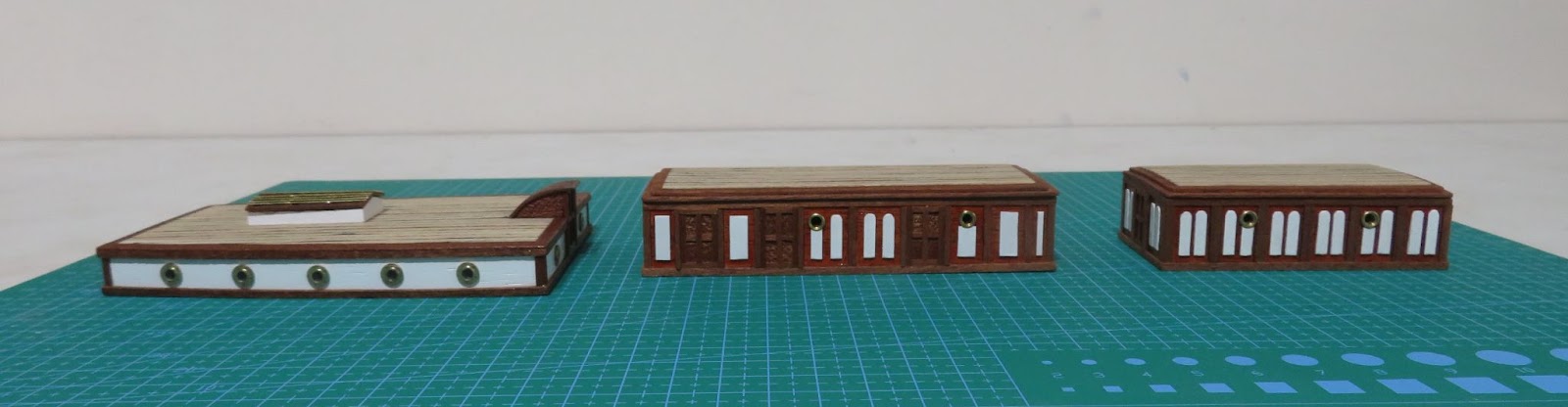
I was not sure which plans to follow because the fabric of the ship changed over the ship's history and the deck houses have been altered from the originals several times. At some point a hatchway was added from the Captain's cabin to the rear of the poop deck (starboard of the ship's wheel) and the main door at the front was extended forward with two doors added on each side. The original plans do not show these features so I decided to follow those. The finish of the houses has also changed over the years - fully varnished (as they are now), painted all white (with varnished doors), the panelling was all white, just the inner panelling was white …… as well as other combinations of white/varnish! All variation seem to have been used at some point so there is no “correct” version (which is not surprising as the ship would have been painted many times during its long working history). I was going to fully varnish them but there is a classic image of the ship in Sydney harbour which shows dark frames with all white panelling on the ‘tween houses, the heads are all white whilst the rear cabin has a white band along the middle (the image also shows that the hatchway at the rear of the poop deck was not added at the time). The second image was taken before the Sydney one and shows just the inner decorative panelling is painted white ( I wouldn’t like to start an argument with those guys!).
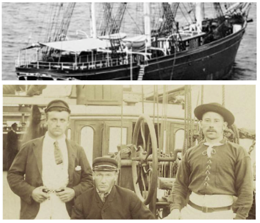
I like the white inner panel appearance but the panel layout has also changed over the years. The panels on the restored CS do not match those shown in Campbell’s plans and Longridge used fewer panels with a simplified design - so I also went that way (to make life easy!). I more-or-less followed Campbell’s plans (position of the doors and portholes) but with a reduced number of panel sections. I used sapele strips to make the frames and a mahogany stain for the panels. To make the white inner panels I shaped some thin veneer strip and painted them before gluing them on. For the 'tween deck houses I went with a dark wood roof margin rather than white so that there was some contrast with the lighter roof planks.
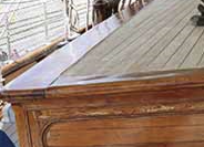
The roofs of the deck houses (and bases) are cambered to the deck. The roofing planks as far as I have been able to find out were the same as used for the main decking. I used 3mm lime planks for the roofs because it would be very difficult to lay narrow (scale) strips neatly (the scale plank size is 1.5mm) and the thread for the caulking would be nearly invisible. It is a bit of a compromise but it allows the use of thicker thread for the caulking to make it more visible and not be out of proportion to the plank width. Looking at various images I could not see any joints on the roof planks so I have assumed that they were full length. For the rear deck house the dark wood margin planks are wider than the roof planks so I used 5.5mm sapele side margins with 4mm margins at the front and rear. I gave the planks a wash with some diluted light-grey stain to mimic the weathered/bleached look you see in the image.
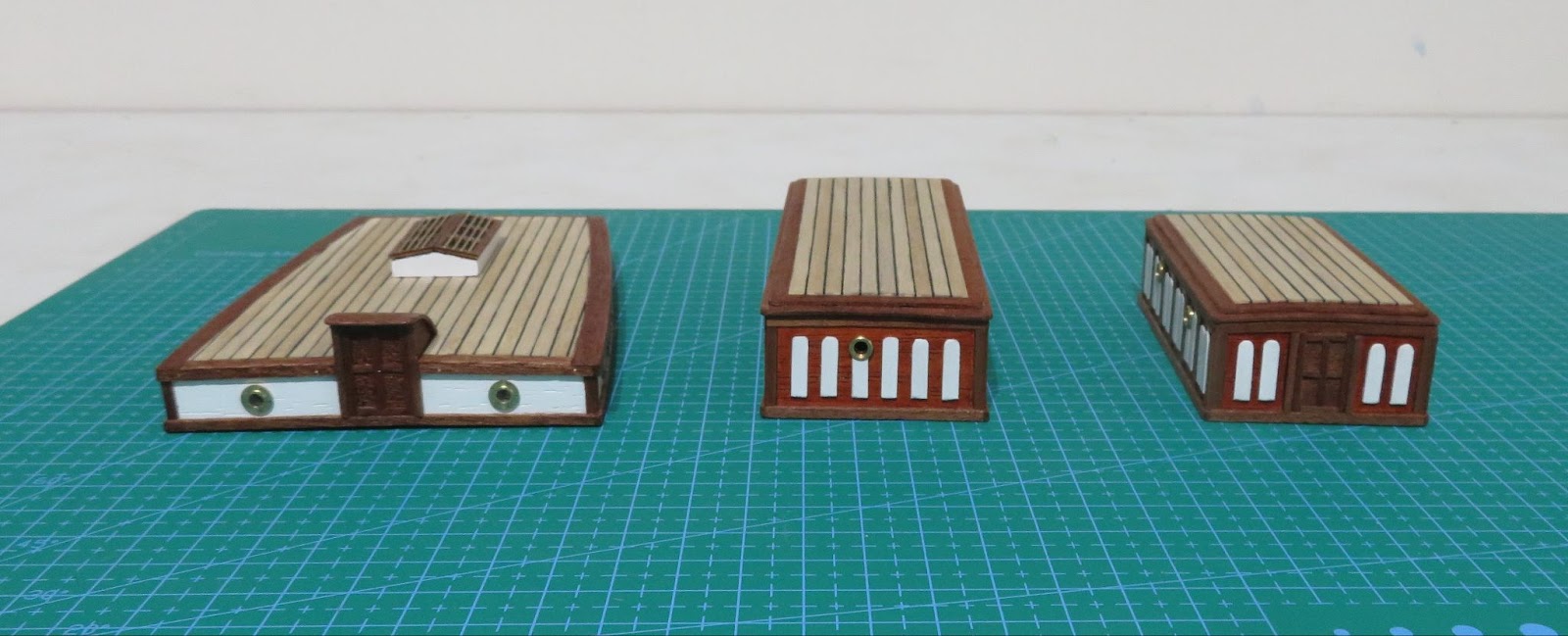
They can now be put out of the way for safety and I will add the detailed fittings when I fix them to the hull.
Next up - ?
Not sure what I will do next. I seem to have abandoned my original build plan but I will probably go back to prep. the main deck area, remove the false stanchions and clean up the bulwarks.
My “other” projects have been parked for the winter so I am now back on the model. I haven’t done any work on it since the end of July so it’s almost like starting a new build.
To get back into the swing of things, I decided to work on the deck houses.
I was not sure which plans to follow because the fabric of the ship changed over the ship's history and the deck houses have been altered from the originals several times. At some point a hatchway was added from the Captain's cabin to the rear of the poop deck (starboard of the ship's wheel) and the main door at the front was extended forward with two doors added on each side. The original plans do not show these features so I decided to follow those. The finish of the houses has also changed over the years - fully varnished (as they are now), painted all white (with varnished doors), the panelling was all white, just the inner panelling was white …… as well as other combinations of white/varnish! All variation seem to have been used at some point so there is no “correct” version (which is not surprising as the ship would have been painted many times during its long working history). I was going to fully varnish them but there is a classic image of the ship in Sydney harbour which shows dark frames with all white panelling on the ‘tween houses, the heads are all white whilst the rear cabin has a white band along the middle (the image also shows that the hatchway at the rear of the poop deck was not added at the time). The second image was taken before the Sydney one and shows just the inner decorative panelling is painted white ( I wouldn’t like to start an argument with those guys!).
I like the white inner panel appearance but the panel layout has also changed over the years. The panels on the restored CS do not match those shown in Campbell’s plans and Longridge used fewer panels with a simplified design - so I also went that way (to make life easy!). I more-or-less followed Campbell’s plans (position of the doors and portholes) but with a reduced number of panel sections. I used sapele strips to make the frames and a mahogany stain for the panels. To make the white inner panels I shaped some thin veneer strip and painted them before gluing them on. For the 'tween deck houses I went with a dark wood roof margin rather than white so that there was some contrast with the lighter roof planks.
The roofs of the deck houses (and bases) are cambered to the deck. The roofing planks as far as I have been able to find out were the same as used for the main decking. I used 3mm lime planks for the roofs because it would be very difficult to lay narrow (scale) strips neatly (the scale plank size is 1.5mm) and the thread for the caulking would be nearly invisible. It is a bit of a compromise but it allows the use of thicker thread for the caulking to make it more visible and not be out of proportion to the plank width. Looking at various images I could not see any joints on the roof planks so I have assumed that they were full length. For the rear deck house the dark wood margin planks are wider than the roof planks so I used 5.5mm sapele side margins with 4mm margins at the front and rear. I gave the planks a wash with some diluted light-grey stain to mimic the weathered/bleached look you see in the image.
They can now be put out of the way for safety and I will add the detailed fittings when I fix them to the hull.
Next up - ?
Not sure what I will do next. I seem to have abandoned my original build plan but I will probably go back to prep. the main deck area, remove the false stanchions and clean up the bulwarks.

Blue yards with white tips would look good. The Captain said so.Blue yards? What's up with that?? I've been to the 1:1 scale Cutty Sark, and they are NOT blue!
It looks like you're in the UK? You MUST go visit Cutty Sark, whatever it takes.
View attachment 324407
Thanks for posting the pictures of the CS. I envy you your proximity to the 'real thing' and what a thrill it must have been to actually set foot on the deck of so famous a ship. Perhaps you can post more pictures as you progress with your model. Then you wouldn't have to do so many at one time. Would make a great addition to the build story too. NorgalePart 7 In Need of Motivation! A Visit to the 1:1
It was always my plan to stretch this build out because of lack of space and other projects that I want to do. However, looking back over the past year, I have not dedicated as much time to the build as I intended and progress has been “glacial” at best. The summer was eaten up by various home/garden/other projects followed by a much needed holiday hiking in the Alps. Now that the Autumn weather has arrived in the UK and outside jobs are winding down I will hopefully have a bit more time on my hands for the model.
Up in the Italian Alps
Before doing any further work on the model, I decided that I needed a bit of “motivation” and headed down to Greenwich - something I have been trying to do for a long time.
View attachment 399824
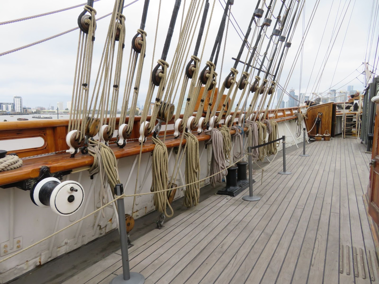
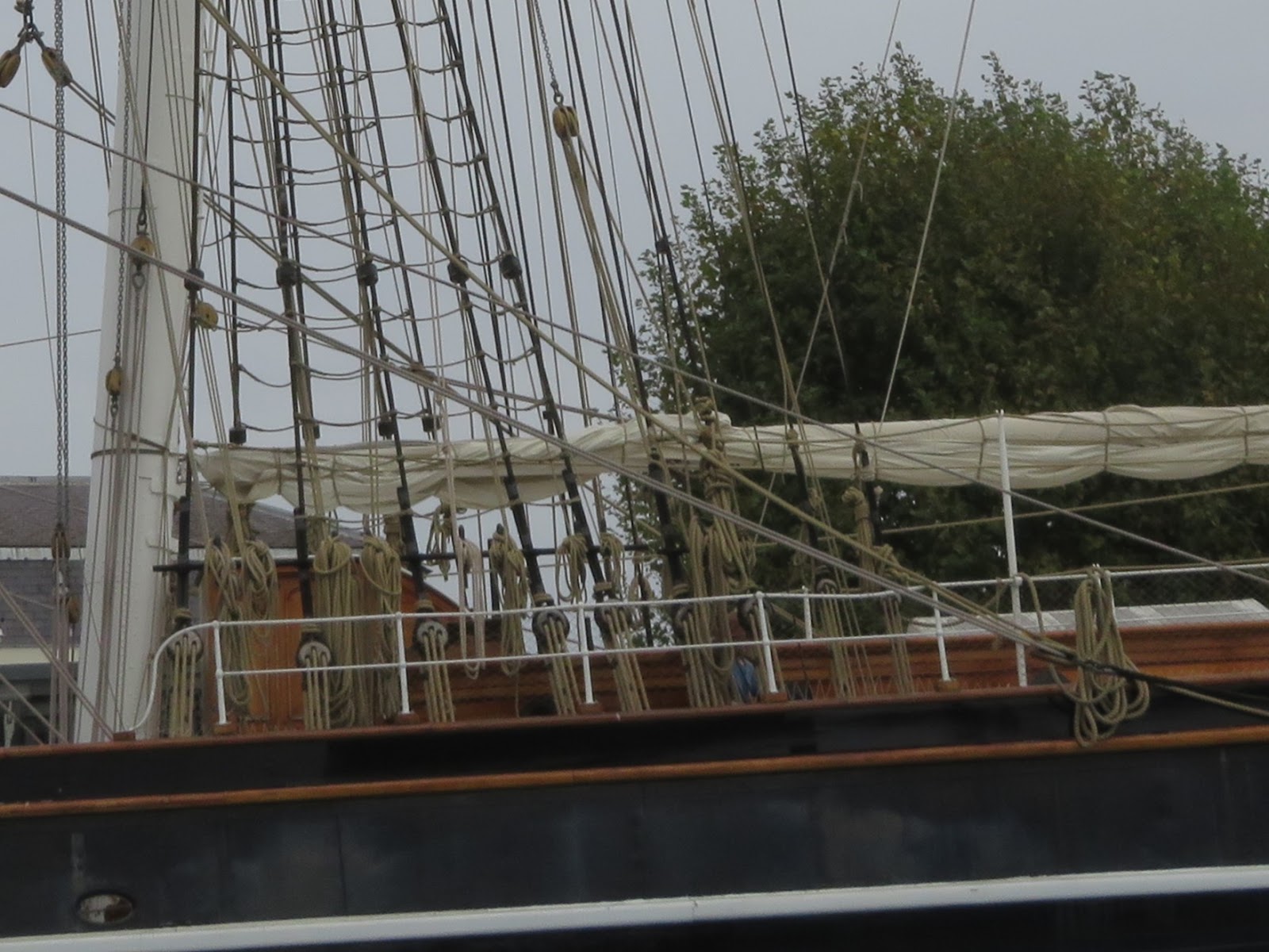
Soooooo much rigging!
Apart from having a nice “motivational” day out, I made a detailed set of reference images for the build. Fortunately, the weather was quite kind to me and I was able to take lots of high res. photographs. I tried to capture as much detail as I could from the deck and from the wharfside - about 250 images. It would not be practical for me to up-load them all to the SOS site but if anyone needs images of a particular part of the ship please feel free to contact me through SOS and I will be very happy to check through and hopefully find something that will help.
Details of the Knights Head
There was some conservation work in progress while I was there and access to the rear deck was not possible. I think some of the visitors were amused by the fact that I was going around with my measuring tape and placing a steel ruler by the fixtures and fittings (so that I could correctly scale the photographs at home) but the conservators immediately picked up on me and said “hi, making a model?”! I had a really good chat with them about the ship and they really appreciated it when I started to ask them specific questions about the construction and rigging. I learned quite a lot - turns out much of the 2006-12 restoration was botched and they are slowly putting things to rights. Really shameful considering they spent £50m ($81m) on the restoration - I think most of the money was spent on “consultants” - it would have been much cheaper to have built a brand new replica ship!
After my fairly thorough “survey” of the ship it was time to have a nice pot of tea whilst sitting under the hull (it’s a tea clipper - what else would I have?). I can only hope that my efforts to sheath the model in brass will look as good!
I also had time to visit the nearby Royal Maritime Museum. The galleries in the museum are now “themed” for visitors to discover and learn about periods of maritime history - all very interesting - but only a selection of the model collection is now on display, the models being chosen according to the theme. For modellers the best place to head to now is the Royal Dockyards Chatham where many famous naval sailing vessels were built. As well as undertaking research and conservation, a large part of the model collection is now housed there and they can be examined on request < The Historic Dockyard Chatham > . Unfortunately, Chatham is an additional 2.5 -3 hr round trip from the Cutty Sark and there is not enough time to travel between the sites and make a worthwhile visit to both museums in one day (I will perhaps make a special trip there sometime in the future).
Now that I have a much better connection to the Cutty Sark and a good set of reference images to work from, I am looking forward to getting on with the build again with renewed enthusiasm! Hopefully, I will be able to make some good progress over the next few weeks with some regular updates to the build log.
- Joined
- Sep 23, 2021
- Messages
- 343
- Points
- 238
Definetely not blue! I think that's just an artifact of the picture. The yards are now black but they were also painted white at times during the ship's history. I am still looking through the archive pictures to decide which I prefer.Blue yards with white tips would look good. The Captain said so.
- Joined
- Sep 23, 2021
- Messages
- 343
- Points
- 238
Part 9. Cleaning up the Main Deck Area and Bulwarks; Forecastle Deck (Big Differences!)
I have been well under the weather these last couple of weeks so everything stopped again - just as I thought I was getting back into the swing of things! C’est la vie! I am now starting to re-join the land of the living again so I have been able to do a little bit on the ship.
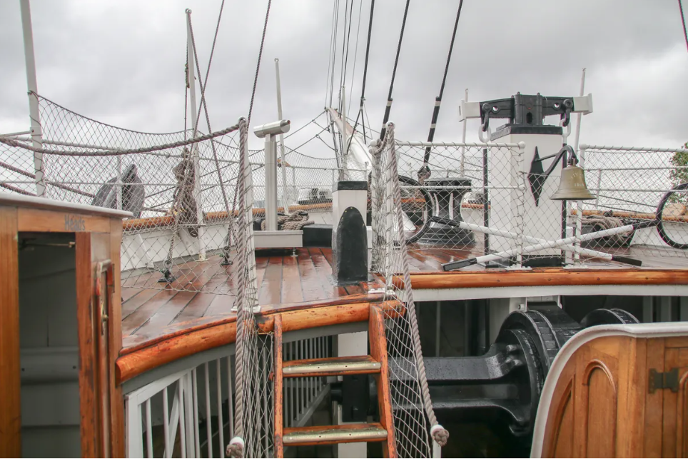
In order that I could correctly measure the length of the main rails that I will make I needed to sort out the forecastle deck and the position of the heads but, it was not as straightforward as I thought. As you can see in the images, the ends of the main rails meet the front edge of the forecastle deck and the heads butt up to it at the back and the deck edge is recessed for the heads to fit into it. The bases of the heads also compensate for the rise of the foredeck.
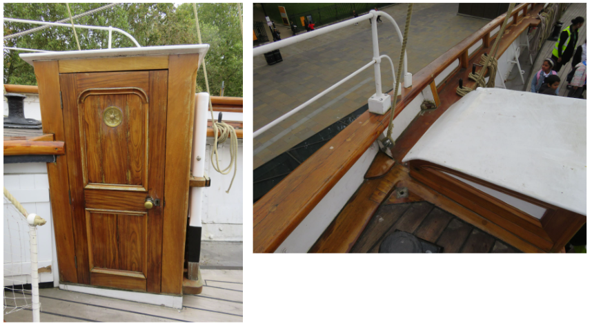
The position of the forecastle deck is therefore critical to know but, the design of the forecastle deck has been changed several times during the ship's history.
The image shows the forecastle deck as the ship is today and it corresponds to the one shown in Campbell’s plans. However, the Billings kit and plans have an extended deck covering the capstan. Which is correct?
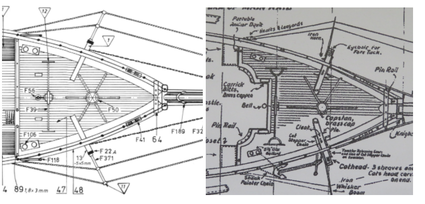
Billing Plans vs. Campbell’s Plans
Historical images I have found show that the deck was indeed extended for a good 50-60 years and the current deck was only fitted when she was restored in the early 50’s after she moved to the dry dock at Greenwich as a museum ship.
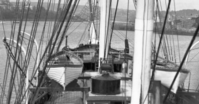
The Forecastle deck as it was when she was based at Falmouth (1922-1938) as a sail training ship (does anyone know what the round structure is on top of the deck house?).
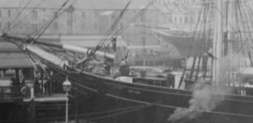
The draft original plans for the Cutty Sark also show an extended deck but it is not clear if she actually started life with that deck design or the one shown in Campbell’s plans. Interestingly, a photograph taken when she was loading in Australia (between 1883 and 1895), shows a cut-out deck with the ladders at the sides and looking closely, the deck does not appear to have the semi-circular cut-outs, the heads appear to be further back and the two side sections are longer and angular - very different again. It may be that the deck was altered when she was refitted for the wool runs in order to cope with the southern ocean (she was already 15 years old at the start of that time so it would be expected that alterations would have been made).
It was an interesting little bit of research but I decided to follow Campbell’s plans mainly because you will be able to see more of the capstan and the pig pens on the model. I used a piece of card to make a template according to Campbell’s plans and then transferred that to some ply and made a new deck piece. I steamed the ply to camber it and once I was happy with that, I temporarily fitted it to the hull so that I could then measure the position of the heads and main rails from it. I will make the heads later.
I cleaned up the inner bulwarks and removed the false stanchions, filled in any holes and sanded the margin areas down which form the water channels (I will paint them light grey). Longridge did not make cut outs through the bulwarks for the clearing ports but instead just attached the “closed” ports to the outer hull and I have decided to also go the “faux” route. I was thinking of using some veneer strips on the inner bulwarks but they will be barely visible under the main rails so I will just paint them white. I will fix some strips to the inner top edge of the bulwarks for the main rails to sit on in order to give them a firmer base and to keep them level. The A-frame supports will be added later because they will be too easily damaged while I sort out the rest of the hull and the main deck covering.
Next up:
 Merry Christmas and a Happy New Year to Everyone!
I have been well under the weather these last couple of weeks so everything stopped again - just as I thought I was getting back into the swing of things! C’est la vie! I am now starting to re-join the land of the living again so I have been able to do a little bit on the ship.
In order that I could correctly measure the length of the main rails that I will make I needed to sort out the forecastle deck and the position of the heads but, it was not as straightforward as I thought. As you can see in the images, the ends of the main rails meet the front edge of the forecastle deck and the heads butt up to it at the back and the deck edge is recessed for the heads to fit into it. The bases of the heads also compensate for the rise of the foredeck.
The position of the forecastle deck is therefore critical to know but, the design of the forecastle deck has been changed several times during the ship's history.
The image shows the forecastle deck as the ship is today and it corresponds to the one shown in Campbell’s plans. However, the Billings kit and plans have an extended deck covering the capstan. Which is correct?
Billing Plans vs. Campbell’s Plans
Historical images I have found show that the deck was indeed extended for a good 50-60 years and the current deck was only fitted when she was restored in the early 50’s after she moved to the dry dock at Greenwich as a museum ship.
The Forecastle deck as it was when she was based at Falmouth (1922-1938) as a sail training ship (does anyone know what the round structure is on top of the deck house?).
The draft original plans for the Cutty Sark also show an extended deck but it is not clear if she actually started life with that deck design or the one shown in Campbell’s plans. Interestingly, a photograph taken when she was loading in Australia (between 1883 and 1895), shows a cut-out deck with the ladders at the sides and looking closely, the deck does not appear to have the semi-circular cut-outs, the heads appear to be further back and the two side sections are longer and angular - very different again. It may be that the deck was altered when she was refitted for the wool runs in order to cope with the southern ocean (she was already 15 years old at the start of that time so it would be expected that alterations would have been made).
It was an interesting little bit of research but I decided to follow Campbell’s plans mainly because you will be able to see more of the capstan and the pig pens on the model. I used a piece of card to make a template according to Campbell’s plans and then transferred that to some ply and made a new deck piece. I steamed the ply to camber it and once I was happy with that, I temporarily fitted it to the hull so that I could then measure the position of the heads and main rails from it. I will make the heads later.
I cleaned up the inner bulwarks and removed the false stanchions, filled in any holes and sanded the margin areas down which form the water channels (I will paint them light grey). Longridge did not make cut outs through the bulwarks for the clearing ports but instead just attached the “closed” ports to the outer hull and I have decided to also go the “faux” route. I was thinking of using some veneer strips on the inner bulwarks but they will be barely visible under the main rails so I will just paint them white. I will fix some strips to the inner top edge of the bulwarks for the main rails to sit on in order to give them a firmer base and to keep them level. The A-frame supports will be added later because they will be too easily damaged while I sort out the rest of the hull and the main deck covering.
Next up:
Merry Christmas and a Happy New Year to Everyone! 
- Joined
- Sep 23, 2021
- Messages
- 343
- Points
- 238
Part 10. Main Rails/Poopdeck Margin.
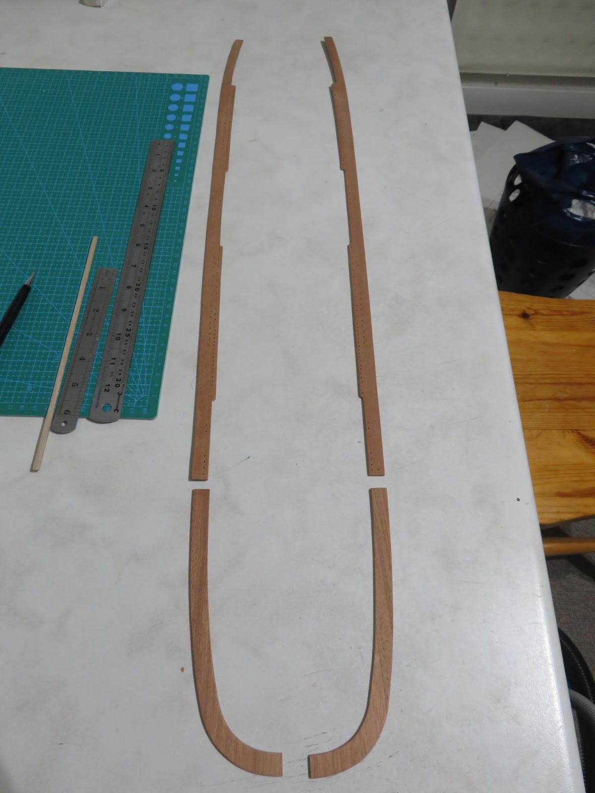
With the position and of the forecastle deck set I could measure off the length of the rails correctly. I decided to make them from solid wood and purchased a sheet of 2mm thick sapele to use for this task so that I had enough material to make them in one piece rather than join sections together. It was a little harder doing it that way, but I thought that they would look better. I rough cut some wide strips using the ply rails from the kit as a guide and allowed a good margin of extra material. To make sure that the rails followed the hull shape I taped the roughed out pieces on top of the bulwarks and marked the hull line onto them and then extended the line by 1/16”/2mm using some masking tape so that they would form the hull strake on the outside and I also extended the line inboard by the same amount to allow for the thickness of the bulwark planks.
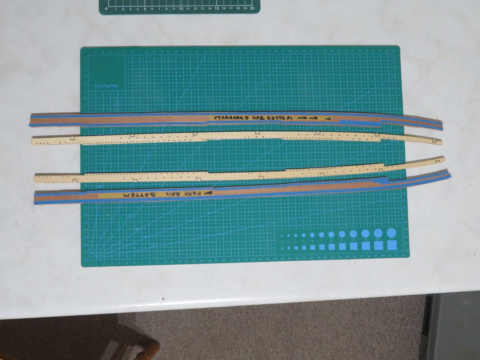
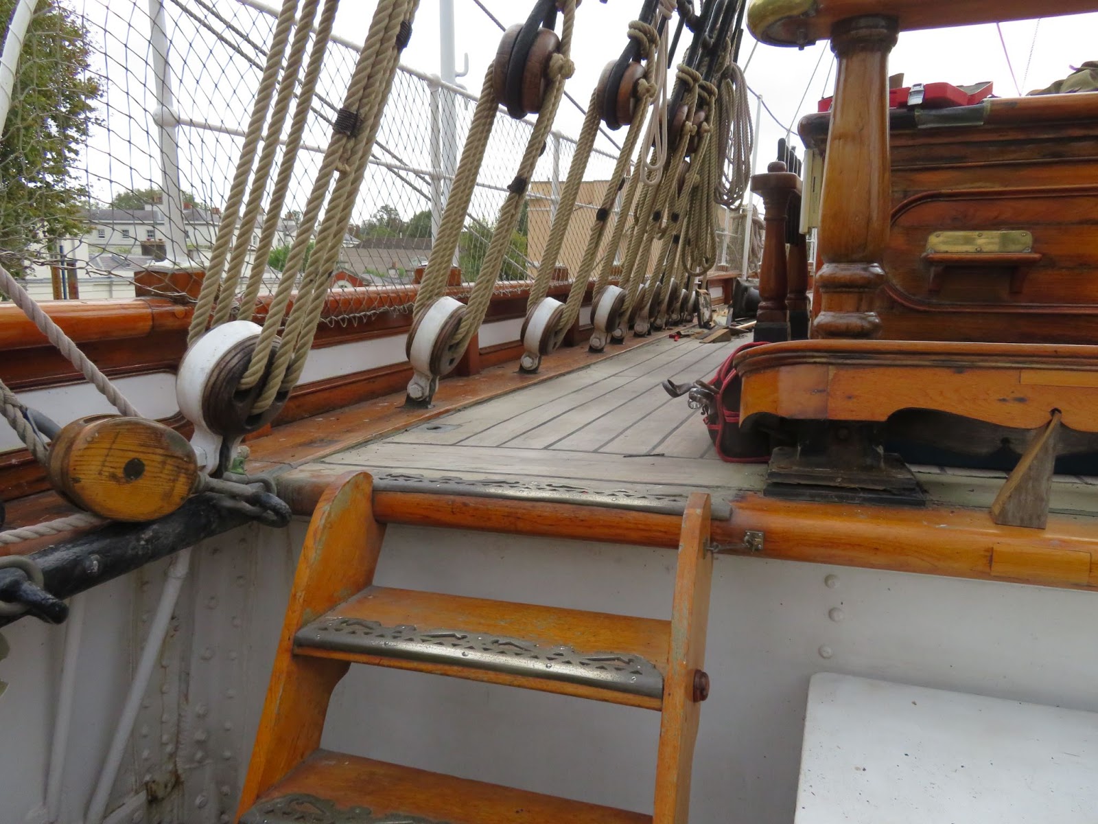
It was then a case of carefully sanding down to the lines. I used a 2.5mm round grinding bit to make a shaper from an old cutting blade which I used to profile the edges of the rails. The final job was to drill out the dead eye positions for the shrouds, the stays and all the pin positions (lots of ‘em!). I initially thought to use the kit rails as a template but after checking them against Cambell’s and Longridge’s plans I found that none of the plans agreed with each other! It was a good job that I took lots of photographs on my visit so I cross-referenced my images with the different plans and decided on a layout that more-or-less matched. The positions (and number) of the deadeyes for the shrouds and stays for each mast was the most important thing to get right. The run of the first shroud (from the bow) for the fore and main runs down the line of the masts but for the mizzen it is set back because the first shroud deadeye is mounted at the very end of the rail which is behind the mast (Longridge has this correct the other plans do not). On the ship, the deadeye strops run through the rails and are bolted to the bottom of the bulwarks but that detail would be very difficult for me to replicate on the model because the bulwarks are only 1/16”/2mm thick soft wood and are not substantial enough to fix the strops to. Instead I will use some 1mm brass rod which I will fix into the deck and also secure them at the rail to make sure that they will not pull up when I tension the rigging.
Deadeyes and strops for the foremast shrouds and stays. Note: the spacing for the shrouds is 2x the stays and the pin rail extends to deck margin.
Mizzen mast showing the first shroud position is behind the mast
On the model, the rails extend further into the deck area than on the ship (where the pin- rail only protrudes out as far as the deck margin). I’m OK with that because at this scale reducing the width of the rail would mean that the pins would need to be drilled very close to the edge which would risk splitting the wood and the deadeye strops need to be far enough forward so that they will not clash with top of the gunwales when fitted - it will also make life a little easier when rigging. I will need to add some more positions for blocks, eyelets and pins later but I will do that once I start rigging rather than randomly drill some holes in the hope that they are in the right place! I will fix the rails into place after I plank the main deck otherwise I will run into trouble.
While I was making the rails it was sensible to also make the margin that sits on top of the poop deck. I made the margin in two sections in the same way as the rails. The margin continues the lines of the rails at the same level and goes around the stern making a continuous band. This band also forms the upper part of the stern decoration (see Part 6). The margin is the same width as the rails. I will need to raise the height of the deck planking a little because I am only using 0.5mm veneer strips which would leave a 1.5mm step rather than be just below as seen in the image. This is a simple fix and I will just glue some scrap 0.7mm veneer sheet on top of the deck area before I plank it which will compensate for the height difference.
Starting to enjoy doing the model after a lot of struggles getting the hull sorted. The little bits of research I am doing at each stage adds a nice dimension to the build so, onwards and ..... something or other? The only fly in the ointment is that the illness I suffered before Christmas turned out to be a kidney stone blockage and it looks like I'm going to have to go into hospital to get it surgically removed - not the best start to the New Year - but what can you do!
Next up: The hull band rubbing strake
With the position and of the forecastle deck set I could measure off the length of the rails correctly. I decided to make them from solid wood and purchased a sheet of 2mm thick sapele to use for this task so that I had enough material to make them in one piece rather than join sections together. It was a little harder doing it that way, but I thought that they would look better. I rough cut some wide strips using the ply rails from the kit as a guide and allowed a good margin of extra material. To make sure that the rails followed the hull shape I taped the roughed out pieces on top of the bulwarks and marked the hull line onto them and then extended the line by 1/16”/2mm using some masking tape so that they would form the hull strake on the outside and I also extended the line inboard by the same amount to allow for the thickness of the bulwark planks.
It was then a case of carefully sanding down to the lines. I used a 2.5mm round grinding bit to make a shaper from an old cutting blade which I used to profile the edges of the rails. The final job was to drill out the dead eye positions for the shrouds, the stays and all the pin positions (lots of ‘em!). I initially thought to use the kit rails as a template but after checking them against Cambell’s and Longridge’s plans I found that none of the plans agreed with each other! It was a good job that I took lots of photographs on my visit so I cross-referenced my images with the different plans and decided on a layout that more-or-less matched. The positions (and number) of the deadeyes for the shrouds and stays for each mast was the most important thing to get right. The run of the first shroud (from the bow) for the fore and main runs down the line of the masts but for the mizzen it is set back because the first shroud deadeye is mounted at the very end of the rail which is behind the mast (Longridge has this correct the other plans do not). On the ship, the deadeye strops run through the rails and are bolted to the bottom of the bulwarks but that detail would be very difficult for me to replicate on the model because the bulwarks are only 1/16”/2mm thick soft wood and are not substantial enough to fix the strops to. Instead I will use some 1mm brass rod which I will fix into the deck and also secure them at the rail to make sure that they will not pull up when I tension the rigging.
Deadeyes and strops for the foremast shrouds and stays. Note: the spacing for the shrouds is 2x the stays and the pin rail extends to deck margin.
Mizzen mast showing the first shroud position is behind the mast
On the model, the rails extend further into the deck area than on the ship (where the pin- rail only protrudes out as far as the deck margin). I’m OK with that because at this scale reducing the width of the rail would mean that the pins would need to be drilled very close to the edge which would risk splitting the wood and the deadeye strops need to be far enough forward so that they will not clash with top of the gunwales when fitted - it will also make life a little easier when rigging. I will need to add some more positions for blocks, eyelets and pins later but I will do that once I start rigging rather than randomly drill some holes in the hope that they are in the right place! I will fix the rails into place after I plank the main deck otherwise I will run into trouble.
While I was making the rails it was sensible to also make the margin that sits on top of the poop deck. I made the margin in two sections in the same way as the rails. The margin continues the lines of the rails at the same level and goes around the stern making a continuous band. This band also forms the upper part of the stern decoration (see Part 6). The margin is the same width as the rails. I will need to raise the height of the deck planking a little because I am only using 0.5mm veneer strips which would leave a 1.5mm step rather than be just below as seen in the image. This is a simple fix and I will just glue some scrap 0.7mm veneer sheet on top of the deck area before I plank it which will compensate for the height difference.
Starting to enjoy doing the model after a lot of struggles getting the hull sorted. The little bits of research I am doing at each stage adds a nice dimension to the build so, onwards and ..... something or other? The only fly in the ointment is that the illness I suffered before Christmas turned out to be a kidney stone blockage and it looks like I'm going to have to go into hospital to get it surgically removed - not the best start to the New Year - but what can you do!
Next up: The hull band rubbing strake
Last edited:
- Joined
- Sep 23, 2021
- Messages
- 343
- Points
- 238
Part. 11 Hull Band Strake.
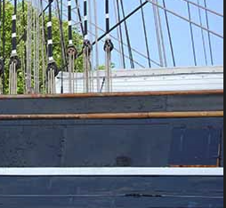
Fitting the hull band rubbing strake was a fiddly job to get the position correct. The top of the band is at the deck level and runs parallel to the top of the bulwarks but it also forms the top edge of the decorative plates at the bow and the lower edge of the stern decoration. The clearing ports also fit between the main rail and the lower band with the bottom of the ports level with the deck.

You can also see in the images that the bulwarks are set back from the lower hull planks because they are iron plates - a detail which I cannot replicate at this scale.
I used a pair of dividers to mark the line of the band from the top of the bulwarks and used some masking tape to stop any glue overspill. I opted to use some 3x1.5mm beech strip which I steamed to go around the stern and pinned it into position with some 0.5mm brass wire and glued it on.
I don’t think it will move while the glue sets!
Because of the rake of the hull at the stern there was a small gap at the bottom of the band and the hull which I filled with some wood putty - “ good enough” - it will be painted over anyway!

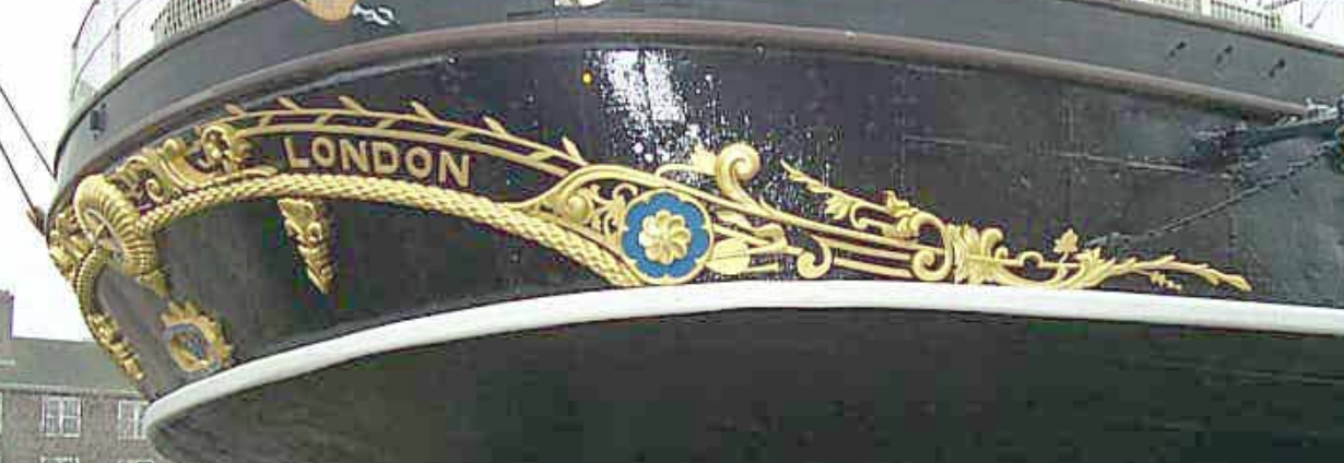
On the beak the band narrows where it comes in to meet the figure head and forms the top of the scroll-work and anchor hause. The kit has some really rubbish pieces of plastic for the decoration and name plate which are nowhere near the correct size so they will be going in the bin!
To make some new plates I made some card templates and transferred the pattern to some 0.3mm brass sheet and cut them out. I temporarily stuck the plates to the hull so that I could position the lower moulding which I made out of the same beech strip. I will attach the photo etch decoration that I purchased from Hismodel to the plates later because they are very fragile and easily damaged, at the same time I will make the anchor hause by soldering a piece of thicker brass onto the plate and drilling it through.

I cannot make the upper name plates yet because they stand off from the hull and the position is determined by the catheads on the forecastle deck which I will not be fitting until much later. I will also need to do something with “Nannie” which was more like a blob of plastic rather than a nice figure head. I started to reshape it with my mini-grinder and it looks a bit better so I will try to carry on with that or possibly buy some pear wood and carve a new figure head.
Rudder
Although not needed at the moment I also made a new rudder using some hard wood. I had to glue two pieces of sapele together to give me the right thickness and used the ply one that was in the kit as a template. The rudder is slightly narrower than the stern post as can be seen in the image and the back edge and bottom of the rudder are slightly bevelled to give clearance as it swings. There are also some cut outs to accommodate the rudder iron hinges.
The rudder irons in the kit are usable but the bands are much wider than scale and do not match the bolt pattern or lengths so I will make some new ones when I fit the rudder to the hull.
NEXT UP:- Brassing the hull.
I have spent a lot of time testing some methods to sheath the hull in brass and have decided on a way forward. It will be a lot of work and will be very hard for me to do as I have never attempted to sheath a hull. I will take my time and post an up-date when I have made some progress. Wish me luck!
Fitting the hull band rubbing strake was a fiddly job to get the position correct. The top of the band is at the deck level and runs parallel to the top of the bulwarks but it also forms the top edge of the decorative plates at the bow and the lower edge of the stern decoration. The clearing ports also fit between the main rail and the lower band with the bottom of the ports level with the deck.
You can also see in the images that the bulwarks are set back from the lower hull planks because they are iron plates - a detail which I cannot replicate at this scale.
I used a pair of dividers to mark the line of the band from the top of the bulwarks and used some masking tape to stop any glue overspill. I opted to use some 3x1.5mm beech strip which I steamed to go around the stern and pinned it into position with some 0.5mm brass wire and glued it on.
I don’t think it will move while the glue sets!
Because of the rake of the hull at the stern there was a small gap at the bottom of the band and the hull which I filled with some wood putty - “ good enough” - it will be painted over anyway!
On the beak the band narrows where it comes in to meet the figure head and forms the top of the scroll-work and anchor hause. The kit has some really rubbish pieces of plastic for the decoration and name plate which are nowhere near the correct size so they will be going in the bin!
To make some new plates I made some card templates and transferred the pattern to some 0.3mm brass sheet and cut them out. I temporarily stuck the plates to the hull so that I could position the lower moulding which I made out of the same beech strip. I will attach the photo etch decoration that I purchased from Hismodel to the plates later because they are very fragile and easily damaged, at the same time I will make the anchor hause by soldering a piece of thicker brass onto the plate and drilling it through.
I cannot make the upper name plates yet because they stand off from the hull and the position is determined by the catheads on the forecastle deck which I will not be fitting until much later. I will also need to do something with “Nannie” which was more like a blob of plastic rather than a nice figure head. I started to reshape it with my mini-grinder and it looks a bit better so I will try to carry on with that or possibly buy some pear wood and carve a new figure head.
Rudder
Although not needed at the moment I also made a new rudder using some hard wood. I had to glue two pieces of sapele together to give me the right thickness and used the ply one that was in the kit as a template. The rudder is slightly narrower than the stern post as can be seen in the image and the back edge and bottom of the rudder are slightly bevelled to give clearance as it swings. There are also some cut outs to accommodate the rudder iron hinges.
The rudder irons in the kit are usable but the bands are much wider than scale and do not match the bolt pattern or lengths so I will make some new ones when I fit the rudder to the hull.
NEXT UP:- Brassing the hull.
I have spent a lot of time testing some methods to sheath the hull in brass and have decided on a way forward. It will be a lot of work and will be very hard for me to do as I have never attempted to sheath a hull. I will take my time and post an up-date when I have made some progress. Wish me luck!