Cutty Sark, Vintage Billing Boats BB564, 1:75.

Good morning Dom. Wonderful progress, she is beautiful. BTW I really appreciate how you layout and present your build log. I always pity the guys looking at my haphazard posts ;) . Cheers Grant
Hi Grant,
I quite enjoy doing the research and I am trying to make the log a bit more interesting by adding in some historical stuff and any images that I have so it's nice to share the info and hope that people appreciate. I think my scientific training forces me to into writing things methodically (OCD!).

Cheers

Dom
 
The lifeboats would also have been stowed with a simple mast and lug sail, similarly the jolly and gig would also have a mast and sail so I may make up something and add them later
Nicely painted. In real life the lifeboats are covered with tarps, which hides all of the bits and pieces. Personally, I prefer to see detail so when I go back to mine, I'll leave them open and probably just use a little bit of rod for a mast and a small rolled up bit of tissue for the sail.
 
After measuring the heights of the skids from the deck I made up the stepped blocks that go on the roof to give me the correct clearance. The hardest part was positioning the fore and aft skids and lining them up so that they had the correct spacing for the boats and then drilling the corresponding holes in the main rail for the end supports.
I hadn't noticed the earlier post - you made a very good job of the skids and well-spotted re' the stepped blocks. I thought I knew the CS quite well by now, but hadn't noticed these. I'll probably tweak the set to include these in future.
 
Part 28: The Railings and Davits


I had hoped to finish this part sooner but things did not go to plan!

Railings: On the ship the stanchions sit on square wooden bases and the lower railing has a slightly smaller diameter than the top one ( See Part 10 image ) I decided not to make the square bases because they would be very tiny, prone to breaking and would make the stanchions too tall. The kit has plenty of two hole brass rail stanchions and I used some 0.8mm brass wire for the top rail and 0.5mm for the lower. The only other thing of note is that the poop deck lower railing does not extend and bend down to the main rail at the ends like the fore rails.

I measured up and then very carefully drilled the holes for the stanchions through the top rail, making sure that the drill was as square as possible to avoid breaking out of the sides of the gunwales. I decided that the easiest way to make the rails was to temporarily fit the stanchions and then feed the wire through each one and then adjust them so that they were all vertically aligned (I used my plumb bob to check that they were straight and vertical to the keel). Once I had everything in place I used some CA to fix the wire into the stanchions and then I was able to just lift the assembled railings off, paint them and then glue them back on. Everything was fine until I caught one of the stanchions and promptly broke one of the gunwales and top railings. There were some wonderful expletives uttered but after examining the damage it wasn’t too bad however, it took me quite some time to make good the repairs.

The Davits: These are of the curved type and are situated at the aft deck house. They pass through the main rail and are located into the water channel. To make sure that the davits were at the correct heights I soldered some brass washers to them so that they sat on the main rails. Not too much work, but I may have some issues with two of the lower deadeyes which are very close to the fore davits but I’ll just have to sort that out in due course.


AD_4nXeTTKMtU9aFuyoXUOhy9IWrXI6qDxeGGk2xyfEIsCvZwplgcneMCtQ7iUIJCZ5Lut0zIK9iDPRhVFVCE3lhm9s3xojsuRkcQ5NzOfmlkZBNwHta6To7_vFPPiForJinMvkgXCVHng


AD_4nXdEaZh_-FBwYMHRDH-5ugug4zbbY-PX5Jg3b-pvGNdXrbzRC_ZthMHMz55UBwBxLkbEpuAC-LOzqU-7ncv1NMxY0tNlzKrZUzvdJYMV-q_gYqfXnQbCety7yXZQ5UbqW6lv7_F9wQ


Next up: There are a few small detailed deck pieces to make up and fit so I will do those next and make a start on stropping the lower deadeyes. I am also working on the figurehead to see if I can get Nannie looking a bit better.


Note: Regarding the boats - all of the plans (Campbell, Longridge and Billing) show the Jolly and Gig stowed upside down which is a bit annoying because the finished boats look really nice. However, I scoured the archives for any photographs that showed the boats in them and I found some that clearly show the boats were also stowed upright at some point in the ship's history. My rule is that if it was like that on the ship at any time during its lifetime then it’s not wrong. I will need to make some chocks for the Gig and Jolly but they are definitely going to be right-side up when I fit them on the model.
 
You've done a fantastic job there with the railings and davits. Even though you are working at 1:75, these are still very small parts and fiddly as hell.

Let's liaise regarding chocks for the gig and jolly. It's not much work at this end.
 
Part 28: The Railings and Davits


I had hoped to finish this part sooner but things did not go to plan!

Railings: On the ship the stanchions sit on square wooden bases and the lower railing has a slightly smaller diameter than the top one ( See Part 10 image ) I decided not to make the square bases because they would be very tiny, prone to breaking and would make the stanchions too tall. The kit has plenty of two hole brass rail stanchions and I used some 0.8mm brass wire for the top rail and 0.5mm for the lower. The only other thing of note is that the poop deck lower railing does not extend and bend down to the main rail at the ends like the fore rails.

I measured up and then very carefully drilled the holes for the stanchions through the top rail, making sure that the drill was as square as possible to avoid breaking out of the sides of the gunwales. I decided that the easiest way to make the rails was to temporarily fit the stanchions and then feed the wire through each one and then adjust them so that they were all vertically aligned (I used my plumb bob to check that they were straight and vertical to the keel). Once I had everything in place I used some CA to fix the wire into the stanchions and then I was able to just lift the assembled railings off, paint them and then glue them back on. Everything was fine until I caught one of the stanchions and promptly broke one of the gunwales and top railings. There were some wonderful expletives uttered but after examining the damage it wasn’t too bad however, it took me quite some time to make good the repairs.

The Davits: These are of the curved type and are situated at the aft deck house. They pass through the main rail and are located into the water channel. To make sure that the davits were at the correct heights I soldered some brass washers to them so that they sat on the main rails. Not too much work, but I may have some issues with two of the lower deadeyes which are very close to the fore davits but I’ll just have to sort that out in due course.


AD_4nXeTTKMtU9aFuyoXUOhy9IWrXI6qDxeGGk2xyfEIsCvZwplgcneMCtQ7iUIJCZ5Lut0zIK9iDPRhVFVCE3lhm9s3xojsuRkcQ5NzOfmlkZBNwHta6To7_vFPPiForJinMvkgXCVHng


AD_4nXdEaZh_-FBwYMHRDH-5ugug4zbbY-PX5Jg3b-pvGNdXrbzRC_ZthMHMz55UBwBxLkbEpuAC-LOzqU-7ncv1NMxY0tNlzKrZUzvdJYMV-q_gYqfXnQbCety7yXZQ5UbqW6lv7_F9wQ


Next up: There are a few small detailed deck pieces to make up and fit so I will do those next and make a start on stropping the lower deadeyes. I am also working on the figurehead to see if I can get Nannie looking a bit better.


Note: Regarding the boats - all of the plans (Campbell, Longridge and Billing) show the Jolly and Gig stowed upside down which is a bit annoying because the finished boats look really nice. However, I scoured the archives for any photographs that showed the boats in them and I found some that clearly show the boats were also stowed upright at some point in the ship's history. My rule is that if it was like that on the ship at any time during its lifetime then it’s not wrong. I will need to make some chocks for the Gig and Jolly but they are definitely going to be right-side up when I fit them on the model.
Some very nice and straight railings, Dom. It accentuates her lines even more. And catching a part ……… I think every model builder can tell a same story.
Regards, Peter
 
Some very nice and straight railings, Dom. It accentuates her lines even more. And catching a part ……… I think every model builder can tell a same story.
ArelRegards, Peter
Hi Peter,
I'm surprised that it's not happened earlier! No doubt there will be more mishaps in due time especially once the bowsprit gets fitted, the thing barely fits on my work bench now.

Dom.
 
Part 29: Under the Weather - Making the Jibboom - Now I Have to Watch it!

I wasn’t able to do much this last couple of weeks after picking up one of the Winter viruses that are going around the UK at the moment………. I have learnt to leave well alone when feeling bad, you only end up going backwards - very fast!

I am still aiming to get the hull work finished before the Spring weather arrives in the UK so, with my batteries still recharging I have just been pottering about in the shipyard with a few smaller jobs.

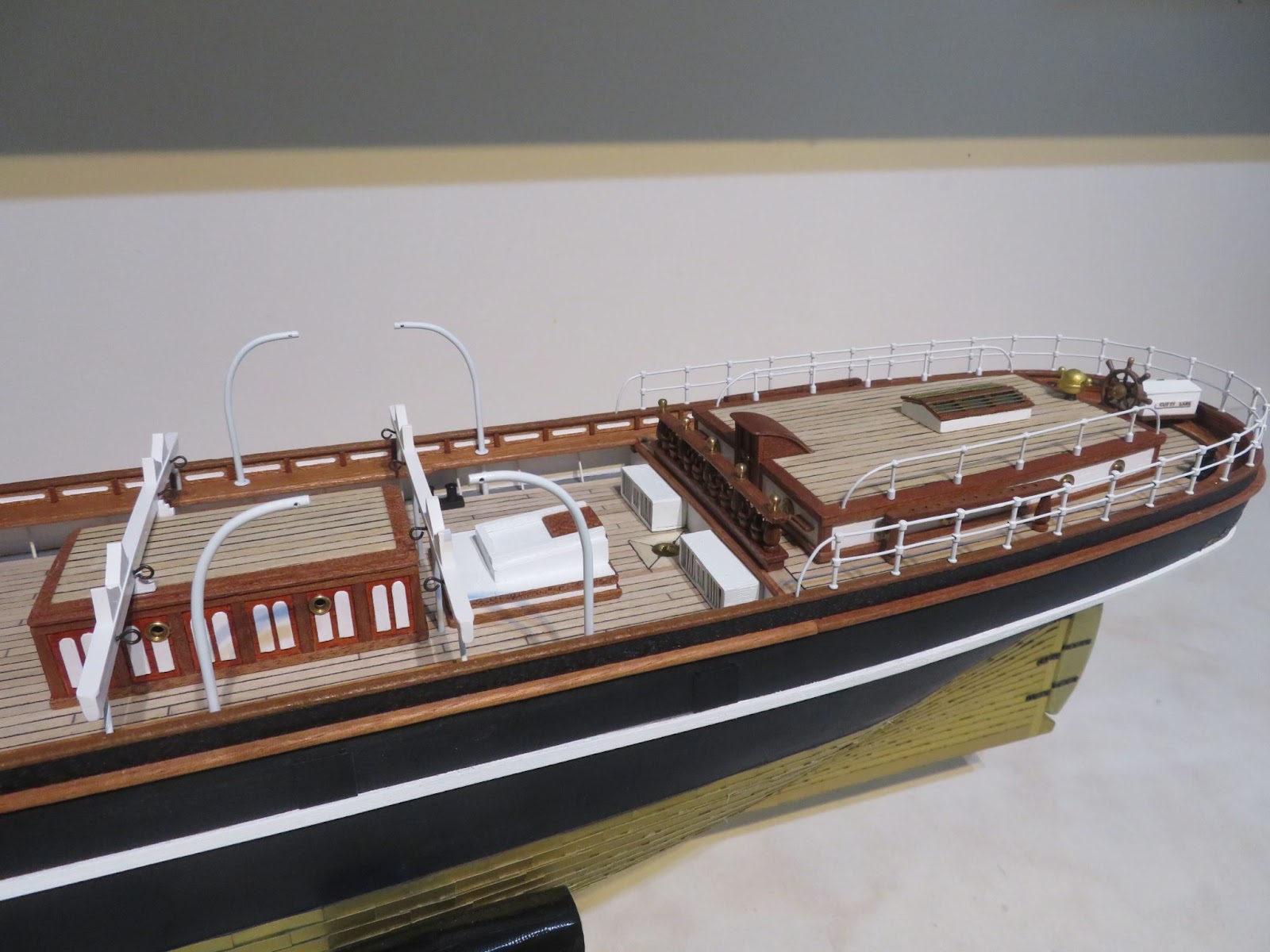
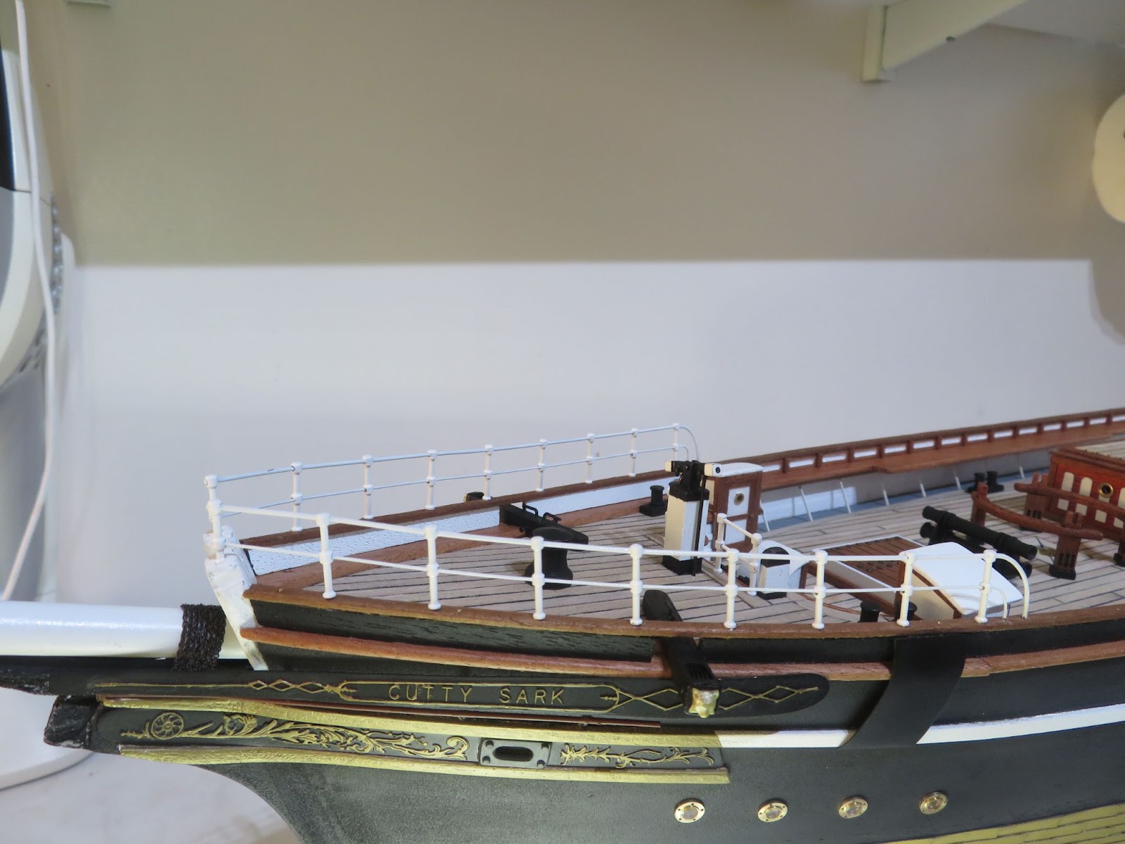
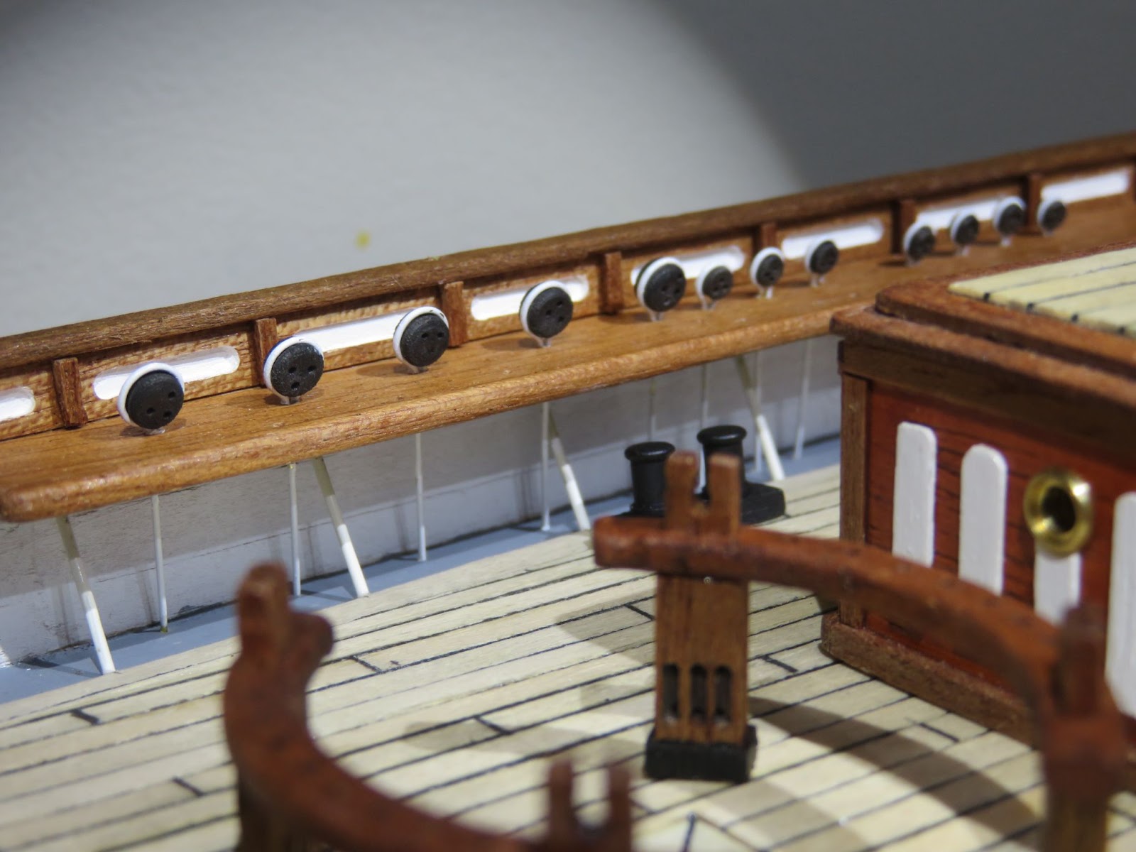
I started with the fairleads at the bow and the stern. I didn’t have the correct single bollard type for the bow but I found some etched brass ones on-line which were OK for the job. The stern ones are just the standard chock style and I used the ones in the kit. With that fairly simple job done I marked out where the rigging blocks on the deck and main rails need to go whilst I still have good access and I will fit them next. After that I was not sure which job needed to be done so after consulting the plans and looking through Longridge, I decided that I needed to sort out the jibboom and the martingale before going any further.


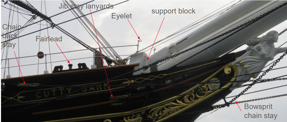
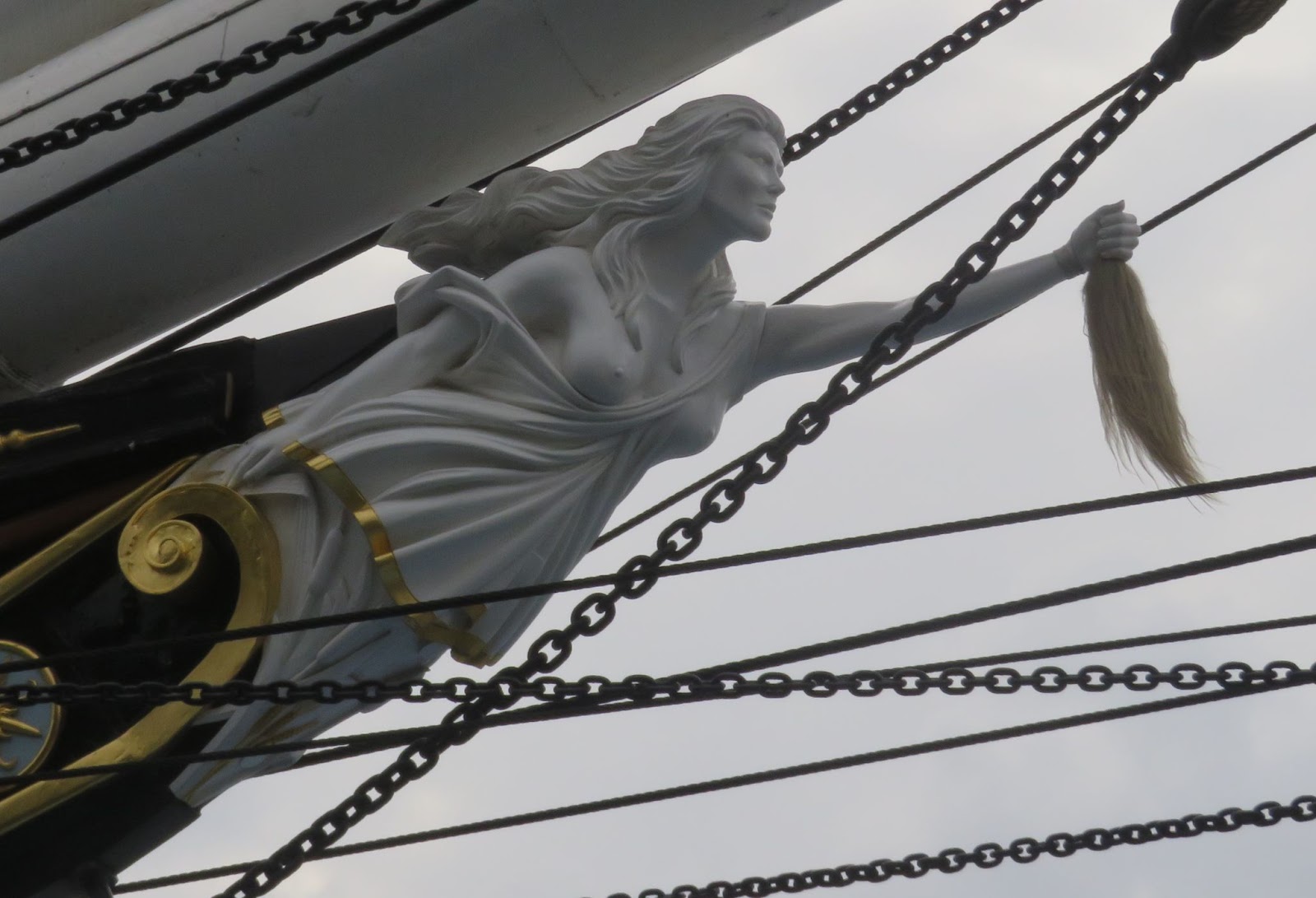
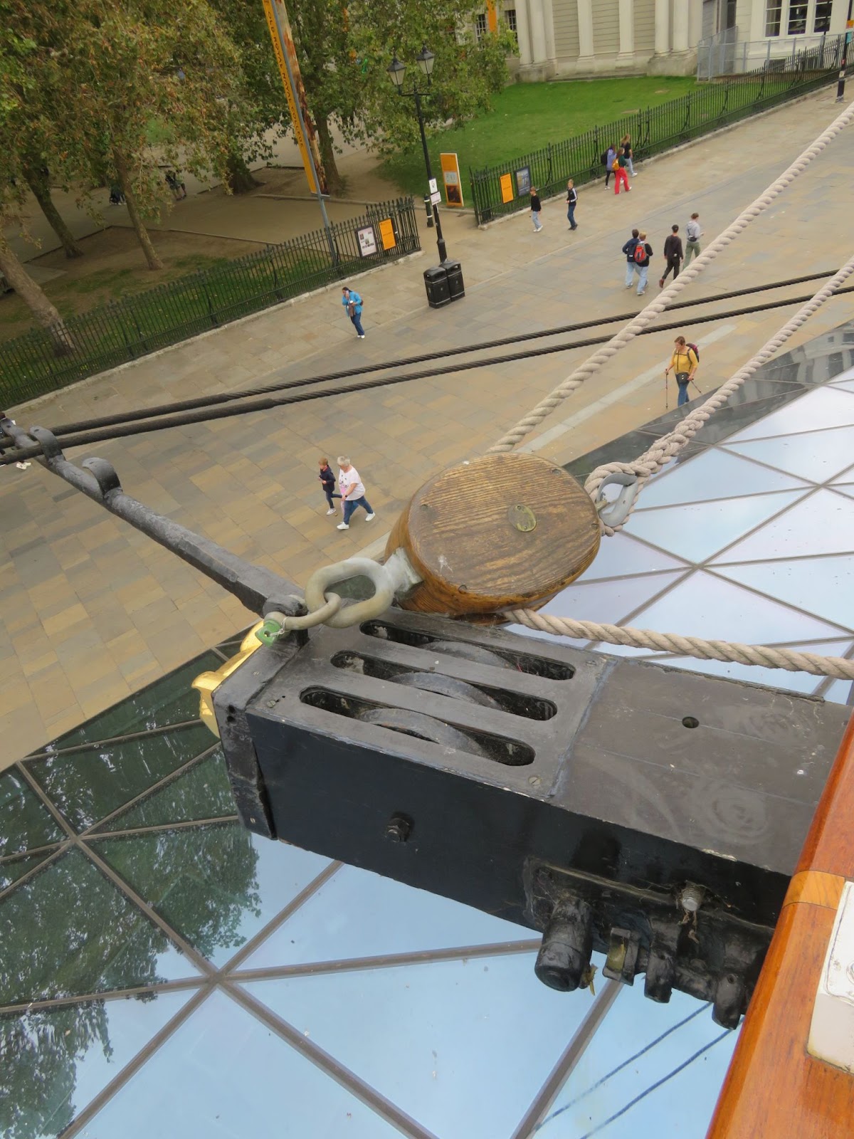
The Jibboom: The jibboom requires quite a bit of rigging to hold it in place as well as a number of fittings on the hull for the jib stays as can be seen in the images. The kit only comes with the bowsprit cap, a piece of 2mm rod for the martingale and a small strap for the lower clamp. Checking my photographs and the plans, the boom also needs two shackles (which were not included in the kit) for the martingale chain stays and the jibboom guys. The martingale back braces come up to the catheads where they are secured using lanyards with bullseyes and the jibboom guys are held in place with the whiskers protruding from the catheads and are then secured to the bulwarks just behind the anchor plates. There are also the bowsprit chain guys that are fixed to the cap and come back to some eyelets under the name plate and are fixed with lanyards. The other main piece of rigging is the chain bobstay which is attached to the bowsprit behind the cap with lanyards and to a shackle on the bow running through a short stand-off to keep the chain away from the figurehead. There were a few other fixings that I had also missed like the eyelets on the top of the rails which are for the hand ropes which go to the eyelets on top of the bowsprit cap.
AD_4nXdRdQZnSLKSrOTA70b6d6me3thvTqADdwYCFfMOtDbRaOQF12SbYe2-EMwaAsLj2J5Q6IpHJk_Ujlbm78YX-9bAqpcPMCetcBzXbXgCeCK4HPcCaowkh4G9v_O6Ik_9z8zJCcpVTQ

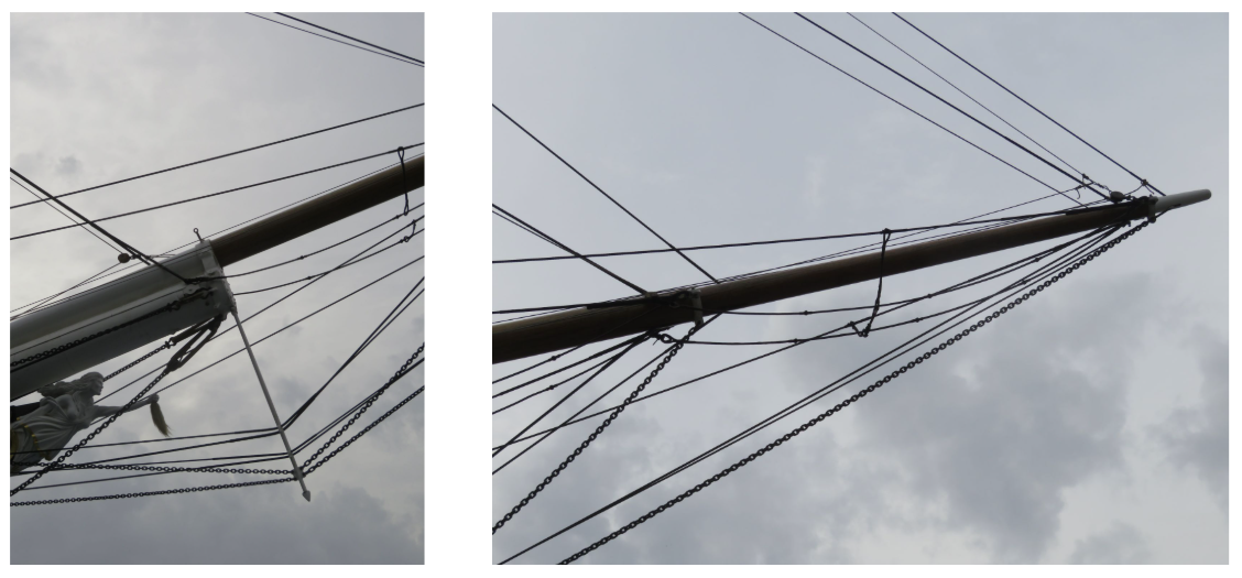
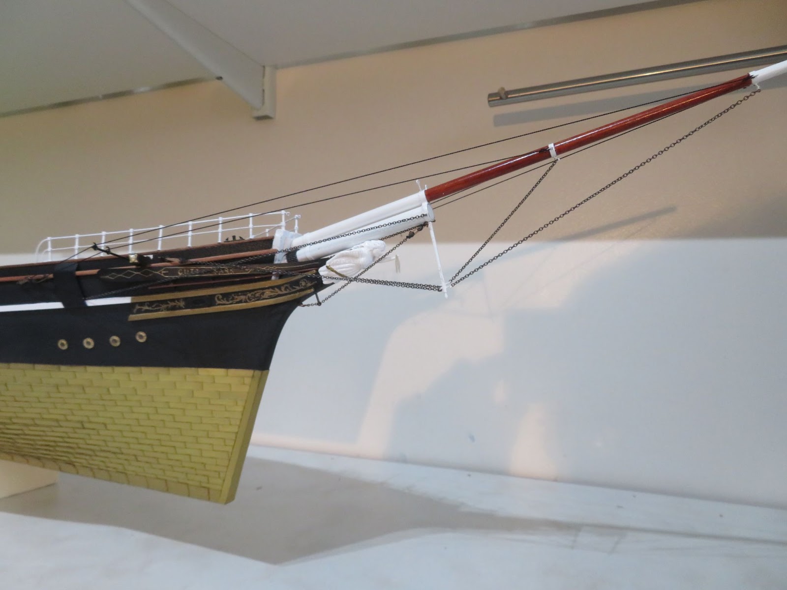
Details of the bowsprit cap/martingale and the jibboom


AD_4nXfdbn57ZIHe63TCDmBarlKubcbisbYI3vViymYP8TWvUYjARAfQECvUmStZsC748bVFTagf0p-47172F3Y3zOo5pXTfZ6WnQFP5PMjJhRtl4onXVzllCy9NZLJmVccvxpsMiRCoJw


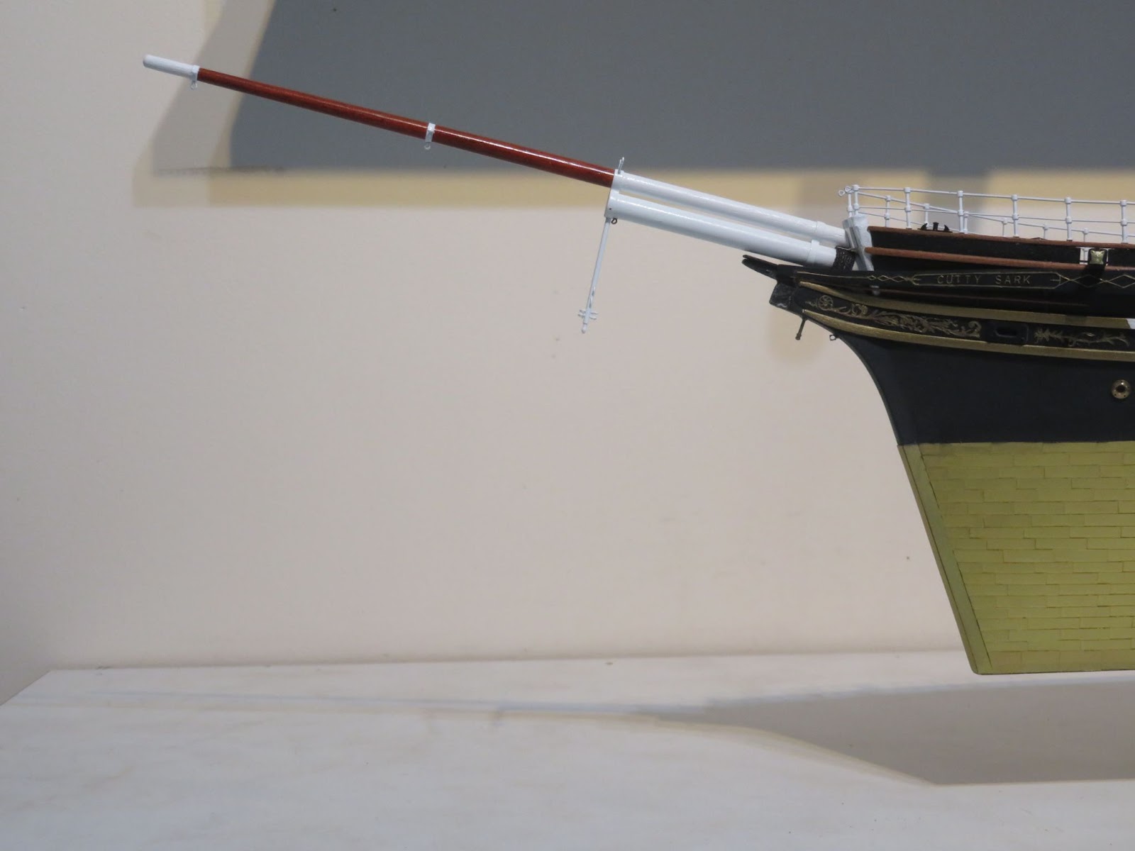
Once I cleaned up the boom I made the shackles from some brass tube and fitted the eyes for the chain stays. The boom itself sits against a wooden board (often missed in many models) to support it at the Knight's head and the base of the boom is angled to fit against that. Interestingly, the base of the jibboom is square from the knight's head up to the clamp and there is a steel sheath beneath the bowsprit but again, very few models I have seen have that detail and, since I also missed it, neither has mine! I cut down a brass rail stanchion to use as the stand off for the chain bobstay and an eyebolt for the anchor point and I will use a long link to attach the chain to it.

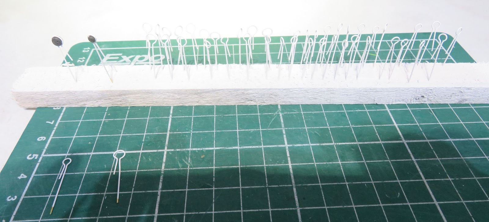
Martingale: The martingale in the kit was 2mm which I thought was out of scale so I made a new one from a 1.5mm rod. The martingale has some clips for the jib stays and a bracket for the chain stays. I decided not to make the bracket (too fiddly for me) so I drilled some holes through the rod and used some 0.5mm brass rod and bent the ends over a 0.7mm drill bit to make some hooks to attach the guys and chains to - I think that will serve perfectly well. The end of the martingale also has a short spike on the end so I cut down a brass belaying pin and soldered that on - good enough. After a trial fit I decided that the lower clamp strap needed to be a bit more robust so I made a new fitting by soldering some brass tubes together like the cap - it’s not correct but I think I prefer to give the boom some more support (for when I catch it!) and it also helps to keep everything properly aligned.


I varnished the middle section of the jibboom with light mahogany and painted the bottom and the tip in gloss white. I have temporarily fitted the jibboom while I finish off Nannie because she will need to be attached before I can fit the stay chains, guys and and bob stay. I also need to make the whiskers for the catheads.

AD_4nXddrOd63UPokhhRemU4xkhlYsdTFsIX8-dqmaX1UyG99OGHc0ZGqQ4Yb9W7oz4jA8ceBnIZSdBxEiXUxksWhoAcCVhT_kmppWMNd3wOevi4y12Yl0Vho9ooURbMXIG_DIqC7_Szlg


Rigging - making a start on planning: While I was not building I decided to gather my thoughts on how to go about the rigging.

My first thoughts, after looking at the rigging and sail plans, was……. to make a run for it! However, when faced with such a daunting amount of work the best thing to do is…. START!

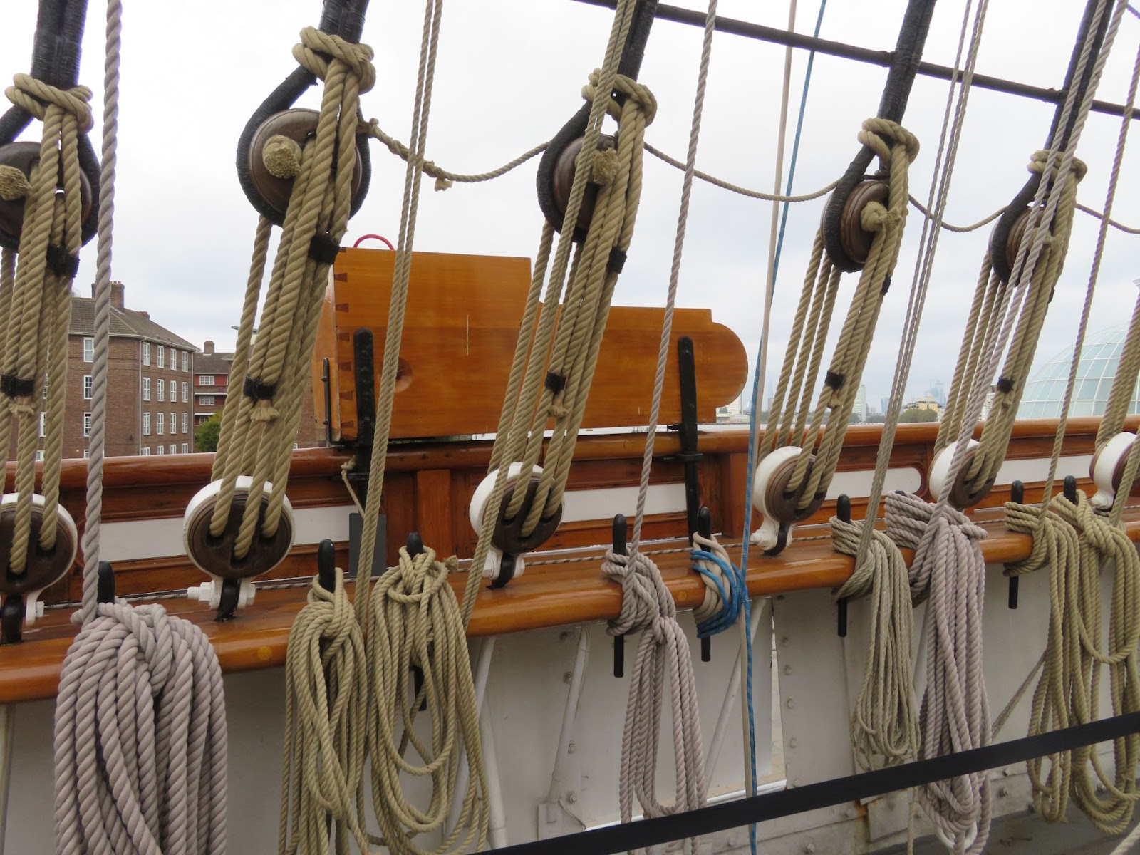
The big decision to make is which rigging thread to use? I have tried a variety of “standard” threads that come with kits and some are better than others but, to do the job properly, I have decided to go with the polyester ropes supplied by Ropes of Scale. In actual fact, all of the standing rigging on the Cutty Sark is steel cable so for me the polyester seems quite suitable for the Cutty Sark. For the standing rigging I will go for black and use light beige for the running rigging. According to Cambell there are 10 sizes of rope/cable but obviously scaled down, the smaller diameters are so close in size I can just go for the nearest. Fortunately Campbell does list all the sizes but I have to decipher which size for which run - such fun! HisModel have sent me a list of the rope sizes recommended for the blocks that they supplied and they have rounded to the Amati equivalent sizes of 0.1, 0.25 and 0.5mm.

The heaviest runs for the Cutty Sark are the lower shrouds and the main stays which scale to a diameter of 0.54mm, so I will go with either 0.5 or 0.6mm (to be decided). The shroud sizes step down quite a lot on each mast so the top mast is 0.3mm and top gallant is 0.2mm. I am putting the sails on so there will be an enormous amount of running rigging needed and most of that will be 0.2/0.3 and possibly some at 0.45mm.

Once I have guesstimated how much I will need of each size from the rigging plans I will order that up from Ropes of Scale. The only caveat is that it is very difficult to know how much “extra” to buy to allow for wastage but it will probably be used on my next build anyway so it’s not a problem.


Next up: Finish off and fit Nannie, fit the jibboom guys and stays and start stropping the lower deadeyes.

P.S. I am taking bets on how long it will take before I catch the bowsprit and break it!
 
Part 30: Nannie, The Cats Whiskers and The Jibboom.

I am still below par after my wintery bugs and I have lost quite a bit of momentum. Until I come up to a full charge again I have just been doing a little bit on the build in order to keep it ticking over. I need to get up to speed again and get as much done before the warmer weather arrives here and my commanding officer hands me my Spring garden projects orders!

Nannie: I needed to finish off Nannie so that I could get her fitted before adding the rigging for the jibboom. She is of course one of the most iconic figureheads and the current version was fitted in 2021 replacing the 1957 one because of rot. The original figurehead was replaced after being lost/damaged in a storm in the late 19th century (I can’t find the exact year). The carving has deep folds in the “Cutty Sark” and she has long swept back hair separated from her back coming up to just below the bowsprit.

AD_4nXdlSrRLhM2Nruhog0LH1WtdRlHelUwaIfyYHqNDBXhnVAIMCEKGMK82YXlDFhaZIPqUSCMfqvtQDV0_fisOCHSPUcy0Msuh7vPXbt88-KWXKxCvUpc89BZPtpqs98MaAhjBdCq-og

Nannie in her “Cutty Sark” of Paisley cloth snatching the tail of Tam O’Shanters grey mare that bears him away from her clutches.

The figurehead in the kit is a very poorly moulded blob of plastic and looks more like a gorilla in a dress! I was thinking about carving a new one from pear wood but I didn’t think it would be worth it as I don’t have the skill (or eyesight) and I would probably only end up with something no better. The best I could do was to add some epoxy filler and then run a fine grinding bit along the pleats to deepen them and add some folds. I also gave her a “hair-do” by layering a little bit of resin over her head and dragging a pin through it as it started to set in order to create some locks. I gave her a couple of coats of white gloss and painted the hem with gold. The only other thing needed was to unpick some thread for the tail hair. Not brilliant but she’ll do - she is a witch after all!

Making the Cats Whiskers and fitting the jibboom: For the whiskers I used some 1.2mm brass rod and some small copper eyelets to fix them to the aft side of the catheads. I deliberately used the small eyelets so that if I caught the whiskers (already happened - several times!) any damage will be minor. The whiskers extend out about 2.5x the length of the outboard cathead and are bent back a few degrees to allow clearance for the fore-tack yard braces and anchor release.

AD_4nXeGLX5ViBl0Tq0PDbnXbzOuw745rrRomYmdj0k5tgPeLK1mATfNH8q4qIfBwh2kNSy6QH7zn2ZbPwNS89dvokiRvVcdSwr6VEi0CFT-o3FhNR6uLGh8SBByKUdt-U7TTxEiLTyu3Q

Port Cat and whisker

There are some cleats at the end to separate the guys so I used some 0.5mm copper wire wrapped around the whisker, glued in place and then folded over.

Rigging the jibboom and bowsprit:

With Nannie in place I finished fitting and rigging the jibboom and the bowsprit.

The chain stays and backstays: The chain back stays for the bowsprit are attached to a shackle on the cap and brackets just in front of the anchor plates using bulleyes and lanyards. The bowsprit chain bob-stay is attached by lanyards to a shackle behind the cap and comes back to the stand-off below the figurehead and attaches to a shackle on the bow. Two martingale stay chains are attached to the lower bracket on the martingale and the corresponding backstays run up to shackles just in front of the Cats and are attached using lanyards. I used the chains from the kit and blackened them with brass black and used some 0.5mm copper wire to make some links to attach them to the shackles. The 2.5mm bulleyes were part of the walnut CnC rigging set from HisModel which I stained black.
The guys: I believe the jibboom was longer at some point, but I am not sure and some images show three pairs of guys and third martingale chain stay were rigged to the jibboom using a shackle about 2/3rds up from the lower one. Campbell's plans show two pairs of guys and chains (as she is currently rigged) and I decided to follow those. The guys attach to the shackles and come back to the whiskers and are then attached using lanyards to brackets on the bulwarks level with the heads. I used some rope left from my last build for the guys (I have just received my new rope from Ropes of Scale so I will be using that for rigging everything else).


AD_4nXcoZ8W9CTwtuEh1RYd4zdQ1TetbV85dMecB4HJjOxkxp7gOQYSkbpjinKJbPD8Z6HSMs2fI9wkhdlVj8UDYTga4ohoKmyr6UKBYuT_CuZdbQJ4wjntM9C0F_4jY3OCWH4dPGS3M


Next up: I am looking at the best method to strop the lower deadeyes which will not be an easy task. There are also a few details to add to the decks and I think I will make a start on the masts.
 
Part 31 The Masts - Well that’s Annoying!

I thought I would add this into the log as a discussion point.

While I was going through the plans, books and images of the rigging to figure out how much rope I would need I noticed an issue /error with the masts and their sizes.

Lower Mast Diameters:

On the Billing plans all three lower masts are shown with the same diameter and I just assumed that is how it is on the ship - which seemed reasonable given that it would have been easier to make three mast sections all the same but with different heights. At the time when the Cutty Sark was built, shipbuilders were transitioning from wood to iron and the lower masts were made of rolled iron plates and riveted together while the upper mast sections were wood (on later ships, before sail was phased out in favour of steam, all steel masts were used when the metals and techniques had improved). However, looking at my pictures I thought the Mizzen mast looked smaller in diameter than the Fore and Main and I simply hadn’t noticed before. Further delving into the specifications that I have found threw up even more differences between the lengths of the sections of the masts with some being quite significant - equivalent to about 10 feet on the actual ship.


I may have missed some details but there is nothing in Jock Willis’s specifications* regarding the mast diameters and lengths:
Lower Masts & Yards, etc. Fore and Main masts and Bowsprit to be of iron, Mizzen Mast to be Vancouvers, Top Masts of Vancouvers, remainder of Spars to be pitch pine or black spruce, spars to be in size as agreed on. All iron masts and steel yards to be made on the most approved plan and in no case less than the size and requirements of Liverpool Underwriters' Rules.
So that’s no help!

*It is no wonder that Hercule Linton went bankrupt agreeing to such open-ended specifications!

In the specification it does not state iron for the lower Mizzen (presumably it was to be wooden) but she launched with all three lower masts made from iron.

The reference to “Vancouvers” stumped me until I found that it is referring to George Vancouver, the naval architect and explorer whose designs (his most famous being HMS discovery) were used as the standard for specifying the size of masts, yards and rigging for sail ships of the age - you live and learn!!!!

Longridge’s scale sizes were based on Kipping’s “Treatise on Masting and Rigging” and using “Vancouver's” design principles: the main mast height is 2-2.5x the ship's beam with the lower mast diameter 1/36 the height in inches and the diameter of the Mizzen is about two-thirds the diameter of the Main mast. When applied to the Cutty Sark with a beam of 36 feet (432”) “Vancouvers” would give a Main mast diameter of 24-30” and a Mizzen of 16-20”. Longridge used a scale size equivalent to Fore/Main 30" and Mizzen 27" (which I think are on the large size for the ship).

After a good deal of searching I found some other numbers but they are all conflicting: Campbell's plans say Fore & Main are 22", Mizzen 21", another reference (unknown source) says Fore 21", Main 24" and Mizzen 18" and Longridge Fore/Main 30" and Mizzen 27". The only other information I have is that the lower masts were the same diameter all the way up. I have sent out a few requests to people who may be able to give me some definitive numbers (including the RMMG) but short of going down to Greenwich with my tape measure, they probably have the same information that I have already found (besides, I don’t have the time to travel down to London, which is also very expensive these days - and I would rather spend the money on some nice rope!).


Mast Section Heights:

Lubbock lists all the heights of all the masts from the deck level to the caps (Tea Clipper rig) https://en.wikipedia.org/wiki/Cutty_Sark#cite_note-66
Sankey lists the heights for Sydney rig
https://en.wikipedia.org/wiki/Cutty_Sark#cite_note-67

This is a table taken from the RMMG web site/Wiki which lists the heights of all the mast sections above the deck which I have converted to 1:75 and compared with Billing’s plans.


Mast Heights
Tea rig
Reference RMMG
1:75 scaleBilling Boats Plans1:75 scale Billing Boats Plans
FORE MASTHeight above deck in metersHeight above deck in mmHeight above deck in mmMast section lengths mm*Mast section lengths mm*
foretop
18.80
250.7
238
250.7
238
topgallant
29.80
397.3
371
203.7
190
royal
39.60
528.0
512
164.7
175
MAIN MAST
maintop
19.75
263.3
254
295.3
254
topgallant
31.90
425.3
384
222.0
190
skysail
44.50
593.3
570
202.0
220
MIZZEN MAST
mizzentop
17.00
226.7
220
261.7
220
topgallant
25.70
342.7
325
161.0
150
royal
33.20
442.7
432
128.0
135

* I will add the socket depth to the lower masts of course (Billing plans use larger socket depths so please note!).

It is also fair to say that the different dimensions may all be correct at some point in the ship's history - she was cut down for the wool runs after 1883 and, after the ship was nearly wrecked as the Ferreira in 1916, the lower Main and Mizzen were replaced and she was re-rigged as a barque (very little detail is available on the mast sizes used when she was converted). The Fore lower was replaced in the 1957 restoration. So …. pick and choose!


I am building my model as “Tea Rigged” and I have made all the mast sockets to fit 8mm masts which is equivalent to 24” on the ship but having found all this information, I decided to go with 8mm diameter for the Fore and Main and I will make a shim and use a 7mm mast (21”) for the Mizzen. Close enough for me! I will use the heights above deck as listed in Lubbock’s book for each of the mast sections and will make the scale lengths to match. I am assuming that the doublings are more-or-less the correct lengths as given in the Billings plans so, I have worked out the lengths of each of the sections based on those numbers.

In conclusion:
suffice to say I was a little bit annoyed to find out all this information but better now than later! I will have to check through the positions of the yards as I build up the masts because they will no longer match the Billing’s plans and because I will be fitting the sails I bought from HisModel, I need to make sure they will fit the new spacings.

If anyone has some better information regarding the mast diameters etc. please let me know.
 
Part 31b The Lower Masts -Update

The RMMG staff very kindly went out with a tape measure and measured the diameters of all the lower masts on the ship! Many thanks to the staff who look after the ship for doing that for me (I hope some of them look in on the SOS)!

So here are the measured diameters of the masts: Fore/Main 31” and Mizzen 25”, which are more-or-less Longridge’s sizes. So the closest 1/75 diameters are Fore/Main 10.5 mm and Mizzen 8.5mm - DAMN!

However, it’s no big deal because I can just turn the ends of the masts down to fit my sockets, easy fix!
 
Part 31c The Lower Masts -Update

And: some more information!


Now that I have some definitive diameters for the bases of the lower masts, I looked again at my pictures and was not convinced that the lower masts are the same diameter from the base to the caps as Longridge says in his book.

Longridge used copper pipes for his masts of one diameter with a scale equivalent of Fore/Main 30" and Mizzen 27". But, as I mentioned in the earlier post, Campbell’s plans say Fore/Main 22” and Mizzen 21” which are much smaller diameters than the actual masts if they were the same all the way up - very confusing. I didn’t think that Campbell would be that far off so, with a little more digging and another email to the RMMG, it turns out that the diameters shown in Campbell’s plans are for the cap tops!


So, the correct dimensions for the masts are

Fore/Main: base 31” tapering to 22” at the cap
Mizzen: base 25” tapering to 21” at the cap


That was a fun bit of research and it was nice of the RMMG staff to go and measure the masts for me!

It was also a nice distraction for me because I am currently making the strops for the lower deadeyes ......... which is driving me nuts!
 
Part 32 Stropping the Lower Deadeyes

I had hoped to work on the lower deadeyes last week but, there’s always something - this time I’m having IT issues i.e. my computer decided to “rather abruptly” die so I wasn’t able to work on the model while I sort that out. Unfortunately, after trying to apply "PCR", my PC is as dead as…. so I’m temporarily working on my steam powered tablet while I wait for some parts to fix my computer.

Back to the task in hand:

The lower deadeyes: are stropped with a band and are bolted to a shank that runs through the main rail and is attached to the lower bulwark with a plate just above the waterway as can be seen in the image.

AD_4nXd9pTG1kCjsVEpkSYlCwfMTYeU0gkJh5msqBOymybLHaoNk5xStMJJwjo7BJPR_3A5zgg51DZnkgYyHuc7RMVcBvKRRoWQl5FxH8e06EX9OkMupZZMFZdF7PqvdVwaDxptwCV6h

The Fore mast deadeyes.

It’s not possible to attach the shank to the bulkhead at 1/75 scale so I had to find a suitable method that looked the part. Billing suggests using some thread to tie the deadeye and then pass that through the rail and pin or glue that to the deck but that did not look very good. I experimented (wasted my time) on a few methods but eventually I decided the best (and simplest) was to make some eyelets with a double tail, one long and one short, from some 0.5 mm brass wire rod. The sets of deadeyes needed are in two sizes, 3.5 mm and 2.5 mm so, I bent the rod around a drill bit of the correct diameter first and then formed the eye using some looping pliers to make sure that all the eyes were the exact same size (I also tried using some copper, iron and stainless steel but they were not as good). I stained all the deadeyes black and painted the strops white with some enamel.

AD_4nXdSM5LIRAFV-b2sLOrzj7TCtnoLPl3cE23ofIZ_HToVW7-MgXnDkZ8HWuweMIdmHIkd_GWOvEbHfq4_9Yt4WQKRFOR5JCCwnr3gZKBAVszPwVSe5iEYBwmGXDCry6gX_cUaeDAZJA


I previously drilled all the holes in the main rail at 1mm so I could use an extended 0.5 mm bit to drill the corresponding lower hole at the back edge of the waterway close to the edge of the bulwark (and yes, I did manage to drill out through the hull, twice! Fortunately, the holes were tiny, so it didn’t take too much effort to fill them in with some paint but it was annoying because I was being ultra careful not to do that). I could then pass both tails through the main rail with the longer one feeding into the lower hole and then bend the shorter tail up under the main rail locking the strop into place (no need for any glue). The deadeyes on the poop deck sit on the margin so the legs needed a drop of CA to fix them firmly. There is enough movement in the deadeye above the rail so that they can be bent forward a few degrees to be in line with the shrouds when I get to that.

AD_4nXdleq37bm1py3HMpQBp42neEwqfw6ikxKqngqQKAF8TucOofz0thCGLNBvbZJUhznfzIK-SjZzOc4ziJ140KOwgeqtXNnzyQyDE_ZwUsZjyTV4adHJQQ481-JUPdVQEoSSYQY8ZJg


I am definitely not looking forward to lacing the lanyards!


Next up: Now that I have all the (hopefully) correct dimensions for the masts I will start to build them up. I think I will make up the tops and trestle trees from scratch and there are quite a few mast fittings that will be needed. I need to go through the plans and Longridge’s book carefully so that I do not miss anything because retrofitting anything once the masts are stepped will be a nightmare. There are also a few detail pieces to add to the deck and hull and I will work my way through those. Unfortunately, spring is now here in the UK and I have a lot of outdoor projects to work on so the ship is heading into the Doldrums again.
 
Back
Top