D805 Piet Hein, ex HMS Serapis, WW2 S class destroyer

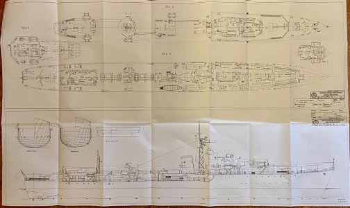
It took a while, but I have the plans! And they are the right ones too! So from here on it's all smooth going ...:cool: ... yeah yeah yeah ..."Get a hobby" they said. "It's the journey" they said.

Seriously: I had some plans, but of the ship in its latest stage with a weird helo deck that was never used. And without proper station profiles. With the new plans I am in a much better position to create a really nice model.
IMG_5871.jpeg
 
It took a while, but I have the plans! And they are the right ones too! So from here on it's all smooth going ...:cool: ... yeah yeah yeah ..."Get a hobby" they said. "It's the journey" they said.

Seriously: I had some plans, but of the ship in its latest stage with a weird helo deck that was never used. And without proper station profiles. With the new plans I am in a much better position to create a really nice model.

View attachment 485968
Always nice to see some NVM plans, Marco. Now some time to read them and make them useful for your project.
Regards, Peter
 
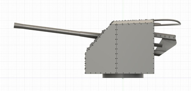
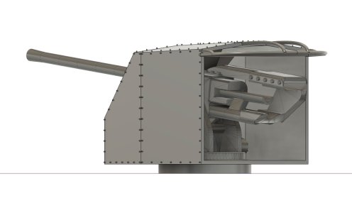
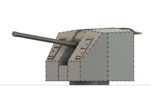
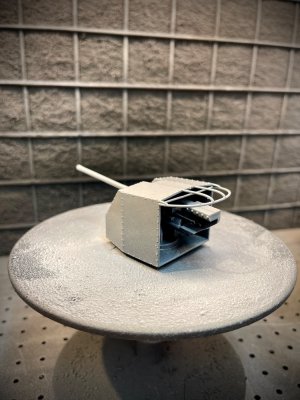
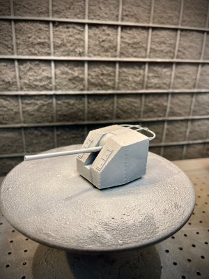
As I was waiting for those plans, I thought "why not start in a similar way as T227 ... with the gun and mount". Turned out that was a smart move. Unbelievable how complex these turrets are to design in Fusion. Lots of angles and slopes, a tremendous amount of rivets (easy to design, but will they show in print?) and the 4.7 inch gun ... It helps when you realise that the whole thingy is about 98 mm from muzzle to last bit of the counter weight. All rivets are 0.35 mm diameter.

Oh well, only one way to find out if this works in 3D print. And I still have to think how to create that canopy at the back. HMS Cavalier has a steel one, but D805 had cloth. I'll think of something, as I want to try my hand in 3D designing these soft looking surfaces anyway. And if all else fails, I will create cloth from some tissue paper and glue that to the ribs.

Screenshot 2024-11-24 at 16.19.28.jpg

Screenshot 2024-11-24 at 16.27.09.jpg

Screenshot 2024-11-24 at 16.18.48.jpg
 
And if all else fails, I will create cloth from some tissue paper and glue that to the ribs.
Using tissue papier is a good option, Marco. Perhaps as you know, Johan @RDN1954 used it on the wings of his Fokker Spider and I made sails of it on my Bluenose. The same thickness of 1 of the layers of a Kleenex tissue is Kashmir Japanese papier. Under the colored text you find the hyperlinks.
You can order it by ‘De Kwast’ in ‘s-Hertogenbosch. Stephan @Steef66 bought it there also and is also experimenting with it.
When it’s not that big, I have still a lot off square-cm’s and can send you some of both. Just send me your adres in a PM.:)
Regards, Peter
 
Last edited:
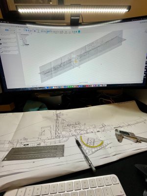
Back to the plans ... and we have a problem. In fact more than one ... I started drafting the three dimensions and from the start had this feeling that something was terribly amiss. And after about an hour trying to think in 3D I figured it out: the drawing is not consequent in scale. And I mean: on one sheet there are at least three scales , approximating 1?100, but way off to work with. So the plan view (top view) does not match the profile view (side view). And the station view is off as well.

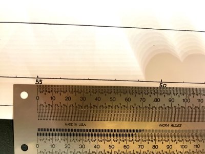
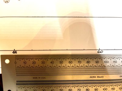
I'm having a hard time finding one reference point for all three dimensions. Why? Because the distance markings on the drawing are equally strange: E.G. from 50 to 55 is not equal to the distance from 60 to 65. Etc. It must be a project to print error. Or a drunk draftsman. Whatever.

So basically I have drawings that are not all 1/100 scale and don't match in views and have variable measurements. Interesting. I will figure it out, but it is rather debilitating.

But once I have the hull correctly dimensioned, the rest will follow.

IMG_5890.jpeg

IMG_5889.jpeg
 
Marco,

On the bottom plan, you have body plan sections with waterline spacing too. The sheer view although to a different scale should allow you to determine spacing of these sections. From this information you should be able to construct a table of offsets to input into your CAD program.

Roger
 
Roger,

Yes, indeed. I just found out that the one drawing actually consists of three moments in time. The original was from 1982, a reworked one was from 1984 and the last one from 1992. And the creators copy pasted parts into their update without being absolutely precise. I still don't understand how a measuring scale in a single can differ over the distance, but that's not important. The major parts (bridge, guns, etc.) are now in their three dimensioned space.

I now understand what's what and found two lines that can be found in all three dimensions. From that I was able to create the offsets as you mentioned. Still a bit of work to get it exactly right, but almost done. And I realise that in the end nobody is going to measure, calliper in hand, each and every bit of the final model.

IMG_5893.jpeg
 
Oh what joy! Started all over, finally with what I thought were three calibrated and dimensioned views. Well, no.

Turns out that the station views, albeit now correctly calibrated, have some interesting deviations from the profile view. I.E. station 40 is shown as at level of H deck at the related station, but in reality should match G deck when following the profile. In other words, the stations are cut off too low.

Again not a real issue and can be corrected, but it makes you wonder if the 'artist' (because that how it feels rather than a draftsman) was on some good dope or booze.

The way out is to draft all stations at the same height (even higher than the highest point on deck) and at later stage make a cross cut along the profile lines.

Still quite a long way from lofting, let alone detailing the hull. But I will get there, no worries. The hull is the most complex task in Fusion anyway.
 
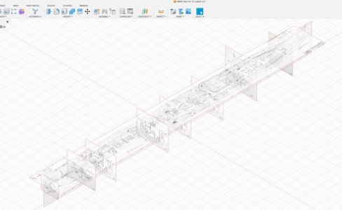
A couple of hours hard work, but I think I have a plan in three dimensions. I took one measurement as "the truth": the beam, approximately halfway, at 10.87 meters in real life (according to wiki, as most sources state approximate measurements only). From there I could calculate what the drawing showed at 1/100 scale and could from there calculate to 1/72. Another thing I did was to actually paste a canvas on each station. Normally you just take one canvas and draw the related lines on each station. But this is more like cutting stations from board. More work, more precise.

Let's see if I can now create a 3D line plan and from there a lofted hull. I think ... will take a bit of time.

Screenshot 2024-12-03 at 21.05.32.jpg
 
Why do I have this feeling that things are going to smoothly ... this vision of cowboys/soldiers stating "it's too quiet".

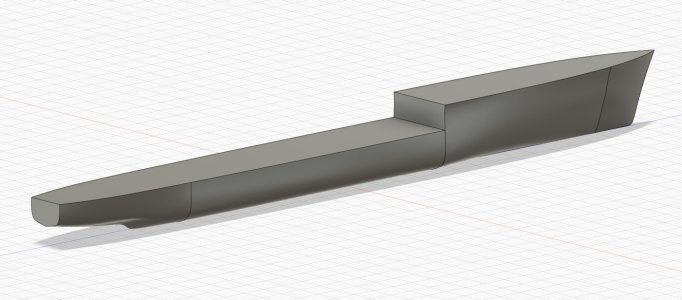
So I managed to create two kinds of loft: one a solid (this image) and a so called "surface loft" (which is just a shell without thickness). Both look promising.

But ...

- I seem to be unable to hollow out the solid one ... if I would print THAT, it would be something like 15 kilos of print stuff (and impossible to print anyway)
- I seem to be unable to thicken the surface lofted one ... which means there is no "body" to print

Oh well, I'm sure I will find my way out of this mess. At least the model starts making sense. Kind of.

Screenshot 2024-12-04 at 17.04.23.jpg
 
It took a couple of nights sleep, which for me always helps solving problems. So I went back to what I knew was good and just erased everything else. Basically everything from where the deck goes up to the bow. I reset the construction planes, created new drawings, ensured I connected the lines where required to be able to loft and hit "go".

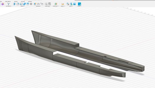
Better, much better. Still a lot of work to be done on the form, with even more to be done on the surface, but really happy with where I'm at. I was even able to hollow the whole thing out and split the body (so I only have to wrestle with one half once I start surface enhancing, after which I simply mirror that half).

Pffff.

Screenshot 2024-12-08 at 15.28.18.jpg
 
It took a couple of nights sleep, which for me always helps solving problems. So I went back to what I knew was good and just erased everything else. Basically everything from where the deck goes up to the bow. I reset the construction planes, created new drawings, ensured I connected the lines where required to be able to loft and hit "go".

Better, much better. Still a lot of work to be done on the form, with even more to be done on the surface, but really happy with where I'm at. I was even able to hollow the whole thing out and split the body (so I only have to wrestle with one half once I start surface enhancing, after which I simply mirror that half).

Pffff.

View attachment 488909
I admire your tenacity, and it looks like a good nights sleep has you back on track, chapeau sir.


Cheers JJ..
 
It took a couple of nights sleep, which for me always helps solving problems. So I went back to what I knew was good and just erased everything else. Basically everything from where the deck goes up to the bow. I reset the construction planes, created new drawings, ensured I connected the lines where required to be able to loft and hit "go".

Better, much better. Still a lot of work to be done on the form, with even more to be done on the surface, but really happy with where I'm at. I was even able to hollow the whole thing out and split the body (so I only have to wrestle with one half once I start surface enhancing, after which I simply mirror that half).

Pffff.

View attachment 488909
I fully agree with Jack. And about the steps fore- and afterwards: it gives me some 'Fushion deja-vu's' ...... But that's the learning curve.:)
Regards, Peter
 
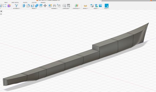
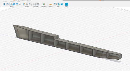
So ... I slept another couple of nights on the hull, as I was still not really truly absolutely happy with the lines of the stern and the bow. With some good forum advice about lofting, some trial and error and with a view on printability I revisited the complete drawing. Every station was drawn again, I introduced a second guide line for the bow and tried all kinds of lofts until I was happy. This must be it.

As the ship will be 6 foot / 150 cm and I can print to 245mm max (and I don't want to go that close to the envelope), I created eight sections. Good thing is that with a simple command (shell) I could also create the required section walls to stiffen up the hull and to create good bonding areas.

Pfff ...

Now to the outside plating. After that I will look what needs to be done deck wise before printing. We'll see. Still lots to be done. But fun.

Screenshot 2024-12-18 at 17.57.01.jpg

Screenshot 2024-12-18 at 17.56.35.jpg

Screenshot 2024-12-18 at 17.57.41.jpg
 
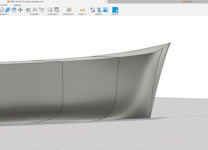
Although happy with yesterday's result ... last night I dreamt about this hull, seriously, and somehow "solved" the real issue: I had way too many spline points (through which the curve flows). A basic mistake, trying to hurry up by taking shortcuts instead of using the curvature handles as I should have. And I want this ship to be up to par.

So I threw the whole bow section away AGAIN and now designed a simple plan.

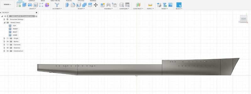
For whomever wants to try their hand at hull design, here's in a few bullets what I did. You will not see it in the image, but on screen, using "orbit" to view the hull at all angles, the hull is now smooth. I started with port holes and such and now feel confident I'm on my way.
  • I created a profile plan in simplest form, ensuring that the actual bow curve was a separate drawing (so it would act as a separate guide)
  • I created three plan views (so top down): one at water line, one at H deck level and one at G+ deck level and made sure these had the correct curvature
  • I created (only) four very simple "ribs" in the higher hull section (so G deck) without additional spline points!
  • I lofted from rib to rib and used the plan views as guides and in a separate loft created the last end to the bow, using the curved separate profile view as a guide. This means the hull consists of five lofts, but as I could use common rails mostly, the flow is now correct.
Onward!

Screenshot 2024-12-19 at 17.20.52.jpg
 
Back
Top