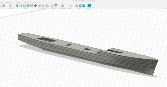
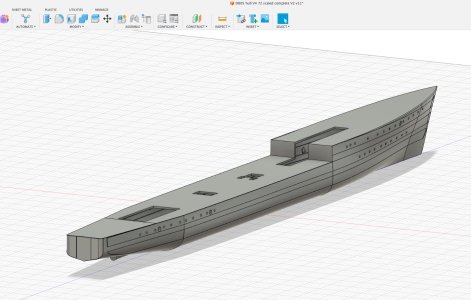
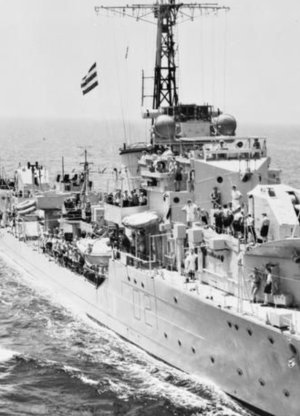
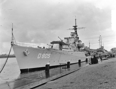
D805 Piet Hein, ex HMS Serapis, WW2 S class destroyer

Although happy with yesterday's result ... last night I dreamt about this hull, seriously, and somehow "solved" the real issue: I had way too many spline points (through which the curve flows). A basic mistake, trying to hurry up by taking shortcuts instead of using the curvature handles as I should have. And I want this ship to be up to par.

So I threw the whole bow section away AGAIN and now designed a simple plan.

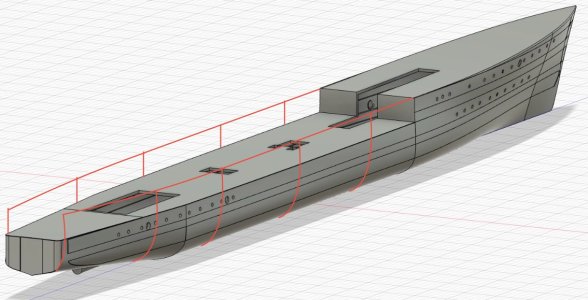
For whomever wants to try their hand at hull design, here's in a few bullets what I did. You will not see it in the image, but on screen, using "orbit" to view the hull at all angles, the hull is now smooth. I started with port holes and such and now feel confident I'm on my way.
  • I created a profile plan in simplest form, ensuring that the actual bow curve was a separate drawing (so it would act as a separate guide)
  • I created three plan views (so top down): one at water line, one at H deck level and one at G+ deck level and made sure these had the correct curvature
  • I created (only) four very simple "ribs" in the higher hull section (so G deck) without additional spline points!
  • I lofted from rib to rib and used the plan views as guides and in a separate loft created the last end to the bow, using the curved separate profile view as a guide. This means the hull consists of five lofts, but as I could use common rails mostly, the flow is now correct.
Onward!

View attachment 490574
What a deja-vu’s, Marco: dreaming thinking about the hull at night, starting for the 3rd time and then the bingo!
This looks very promising.
Regards, Peter
 
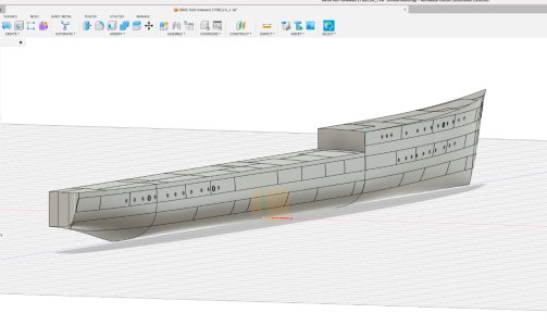
I had two quite productive days and managed to create the required detail in that hull before going to the print phase. Some edges and faces will have to be hand sanded after print as I'm simply not (yet) able to create that level of detail in Fusion. Tough part was getting the thickening in some of the hull. I had to choose between raising some "bars" or depressing others. In reality these plate differences are only something like 10mm ... so in 72 scale ... I chose 0.2mm, as otherwise it simply is not printable.

It is rather a steep learning curve. But this looks like a destroyer hull.

A first simplified and very scaled down print showed only minor faults, so now I will go for one section at scale. Remembering Sir Gareth that will take some 10 hours printing for the one section. Hoping that the 0.2mm will show.

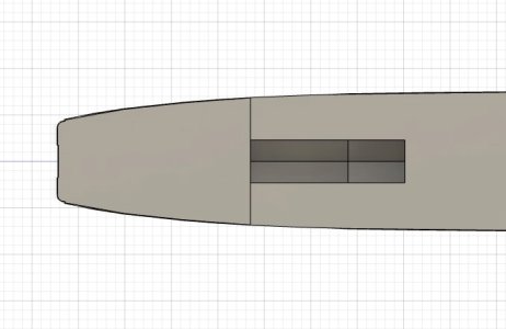
Last screenshots from Fusion ...

Screenshot 2024-12-22 at 12.46.41.jpg

Screenshot 2024-12-22 at 12.46.58.jpg
 
Hello Marco,
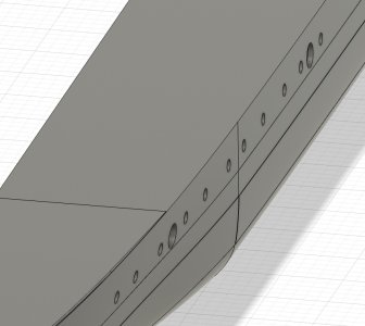
Hoping you don't mind and hopefully my eyes are deceiving me, but it looks as if the transition from mid- to aftships shows a discrete kink instead of a smooth tangent transition. It also shows in the edge lines of the deck. Maybe worth to have a closer look at.
Kind regards, Johan
 
Last edited:
Johan hi

No, I don't mind and actually like a critical eye and comment! How else can I grow?

These kinks: that is why I will do a full print of a section and will ensure that a kink is in it. I had the same hesitation about these lines, but when I "free orbit" I don't see these kinks. So only one way to test: print.

If it's just minimal I will sand it out, as I will do some sanding anyway. FDM printing will leave print lines, even at finest setting. It will require at least three, perhaps four layers of filler from a rattle can (Alabastine, car filler) to get that hull smooth.

Tomorrow will show ...

Cheers, Marco
 
Ah, there actually was at least one kink: with those raised plating I somehow did not connect fully to the next one. So it is actually a very small gap, showing like a ridge.

Good oh!
 
Does Fusion have a function to analyze curvature and continuity? That would allow you to iron out the bugs before printing. Sometimes our eyes are not the most reliable tools.
It does, but more for where your curves are too steep. And I'm still at the level of "oh, yeah, that figures".
 
And as this "kink" idea bugged me and I didn't want to waste 10 hours printing ... and I actually tend to think a little longer about remarks ... I found the way to create a continuous guide along the midships and stern sections.

Oh boy, learning. Fast.
Screenshot 2024-12-22 at 15.14.46.jpg

Screenshot 2024-12-22 at 15.40.11.jpg
 
Last edited:
And as this "kink" idea bugged me and I didn't want to waste 10 hours printing ... and I actually tend to think a little longer about remarks ... I found the way to create a continuous guide along the midships and stern sections.

Oh boy, learning. Fast.
View attachment 490985

View attachment 490989
Hey Marco,

When looking at your surface model, I couldn't help but wonder if it would have helped you if you modeled a surface over the height of the fwd hull. In other words, extrapolating the frames to the height of the fwd frames, followed by creating a surface over the length of the hull. Later, after having generated a skin, you can split the skin to obtain the desired jump from the front- to the aft deck.

Johan

IMG_0993.jpeg
 
Ah, but that was what I did anyway. I worked well above any decks and only made the profile cut after all was done. But what you suggest makes sense. I did two “heights”. Hmm…

So do all at highest level. Hmmm.


Sound advice.
 
I ran a couple of test prints at correct scale and immediately found a few areas that need additional work. But that was to be expected. The computer rendering only shows so much and being able to turn the actual thing in your hands provides a much better view on curvature.

First thing I am going to do is work on that bow. In profile it is 8 out of 10, but head on it is way to sharp. Good thing is I got some good advice and I know how to approach the problem.

Good fun!

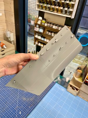
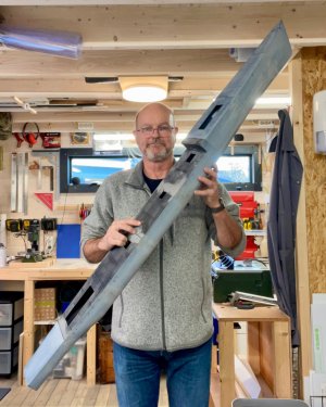
The image shows two sections … of eight. It is going to be a BIG model .Oh, those thingies are supports for openings. They can be popped out easily.

IMG_5938.jpeg
 
First: thanks for taking the time to really look at the hull and for the open criticism. Appreciated!

The vertical is a seam between two printed parts. They will have to disappear with filler and sanding.

So no worries. Ugly now, better after.

But …

These destroyers had a very straight raised plating over the full length of the hull. Barely discernible, but there. Verticals are really thin.

But of course I will work on detail: this was a test run for the overall shape. My plan is to “etch” verticals of (I think) 0.1 mm and then of course staggered. I have a drawing showing how wide these plates should be. Then another test run to see if the hull “comes alive”.

But the horizontal stretches (0.2 mm equals 3.5 cm in real life) are what they are.

Here are two images that show detail.

IMG_3998.jpeg

IMG_0020.jpeg
 
Well, I went back to the CAD drawing ... call it perseverance or just bloody well "will get this right, whatever" ...
- set a camber for the decks, having found that it should be 1/4 inch per foot across
- have initialised a little flare at the stern (eyeballing it from images)
- created raised plates and weld seams all over ... will have to see how that works out
- loft is OK now for overall shape
- weld seams are OK ... until I've seen the test print

Next steps:
- implement construction to strengthen the hull for cutting, printing and then bonding parts together
- test print again ...and again ... sigh

Bit by bit ...

Screenshot 2024-12-29 at 17.40.32.jpg
 
Well, we're into the second week of 2025 already. I hope everybody had a good start.

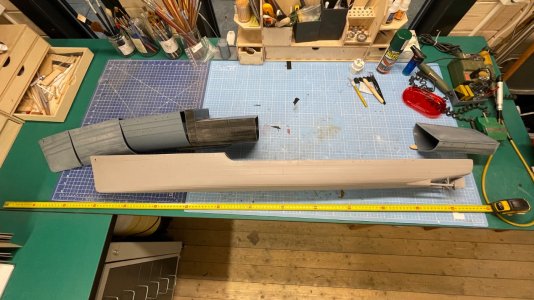
I haven't been sitting still, but was struggling with that hull. Another test run showed way too many issues and, surprisingly, that I actually had too much detail regarding the "weld lines". So I simplified the lot and started printing for real. With some luck I will have all eight modules ready tomorrow. And boy, it is going to be BIG. There will be lots of work to do on the printed hull, comparable to using a commercial one. But that was to be expected. Sanding, primer coating, filling of gaps and such. And bonding the modules together into one hull will be interesting. I'm sure I will put some strips on the inside to ensure the whole structure is sturdy enough. But that's fun.

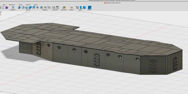
Now that the production run for the hull is on the way on the FDM printer (the one with a nozzle) I started focussing on the deckhouses and other main structures. These will be printed in resin and I plan to work a lot of detail already in at the baseline. We will see how that works out.

Here are a few images. I put my old 1/96 scale hull next to it for comparison. I am still missing three elements ...

And you can see a screen grab of the deckhouse under the bridge, which is actually in print as well, as we speak.

IMG_5960.jpeg

Screenshot 2025-01-08 at 15.47.21.jpeg
 
Hi Marco now that I see the sections it is looking that it will be quite a bit larger than your 1/96 hull. Are you adding the rudder/ rudders and propellers separate on the new hull? And if not can you mark the stern section with accurate drill points? Something I would like as it is (for me) quite a task getting the exact spot. Probably stupid questions, but my 3D Printing for dummies book hasn't shown up yet.
All looks great. Charge on I am looking forward to see the sections all joined up.

Cheers JJ...
For the shaft and propeller I took the angle over from the drawing and created two “starting funnels” sloping from the inside through the hull. I will trim those down on the outside and perhaps do some moulding to make it perfect. And have a “maybe” plan to motor the propellers … just for fun.

The single rudder is fairly simple to implement. Just so many millimeters from the flat stern, straight down.

Of course it helps I already built her before, be it at 1/96 scale.
 
Back
Top