Cad design drawing the steam frigate Mississippi

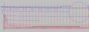
end of the week and an up date on drawing frames. Yup 21 frames done and about 65 more to go.

What I started doing was to draw the frame to the deck line (top row) later adding the bulwark, then realized from Winston's bomb vessel cross section build when you break down the frames into floors and futtocks the laser is taking out .012 thousandths top and bottom of each piece and with 5 ends per frame that is 5 X .012 so the frames total length will be short of the sheer line.

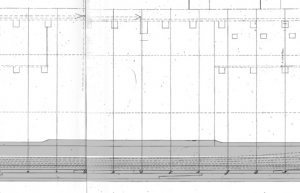
that black line running above the hull and frames is a Harold Hahn idea to create an upper base line, you can see in the second line the frames extend above the hull sheer line. It is a far better idea to create a jig above the hull rather than sitting the hull into a jig. When the hull sits in the jig that jig blocks any work to sand the hull or add wales etc. The purpose of using a jig in the first place is to hold the frames in place so you can sand and secure the framing, if you have to remove the hull first before you can do work that defeats the purpose of the jig.

Just at this stage of a project you have to pre plan and think ahead so you don't build yourself into a situation you can not correct later.

This hull has filler frames between the floors making the bottom of the hull a solid structure so the build and stack method might work

frame progress1.JPG
 
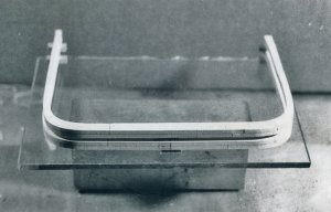
the build and stack methods works like this. Starting with the mid ship frame it is set on a piece of glass with spacers at the top and bottom. In the case of the Mississippi hull the entire bottom is filled in.

arg5.jpg

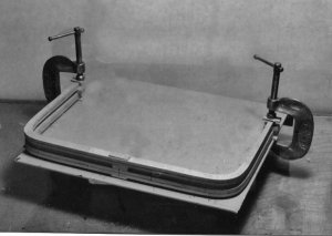
the spacers are added and the frame is clamped in place.

arg17.jpg

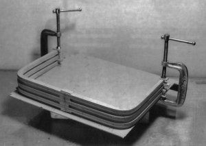
you keep adding spacers and frames stacking them one on top the other.

arg18.jpg
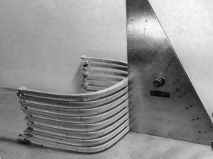
when you get to 10 frames you stop and this will be a unit of the hull section. Building the hull in 10 frame sections then once you have all the sections built then line them up along the keel.
The trick in this building method is keeping the frames square at the face ( on the glass surface) and at a 90 at the keel.

arg2.jpg

this method should work because the hull of the Mississippi is pretty straight along the sides and the hull has little shape along the length except at the bow and stern.
 
ME TOO DAVE, Are you contemplating having kits for the X SECTIONS AS A PROJECT. THANKS Don

yes I plan on creating the working plans and develop a project. However, if anyone wants to step up with ideas on a X section and create a kit project go for it I will make all my material available.

or in time I will carry it through if there are no takers. Sometimes prototype builders are needed just to speed things up.
 
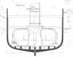
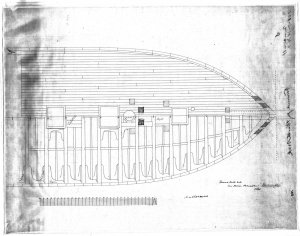
take a look at the inside profile drawing notice the amount of timbering at the keel in relation to the hull it is a massive amount of timbering but then again this hull has to support a steam engine, boilers and guns that weigh tons.Sheer graphic1.jpg
 
looking at a cross section there were 6 sister keelsons plus the ceiling planking was a thick as the frames at the side of the hull

Cross-Section.jpg
 
Last edited:
while I do the drawings I also continue with research and I ran into a snag

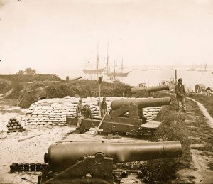
one source states the guns were 8 inch Paixham shell guns these guns were used in France, England , Russia and Germany circa 1840s I can find NO reference to a Paixham gun in any archives here in the states. So how did they get on the Mississippi? OR were they actually a Dahlgren gun? What did a Paixham gun actually look like?

Do you ask us, or do you prepare your next post? :cool:

https://en.wikipedia.org/wiki/Paixhans_gun


United States[edit]
The United States Navy adopted the design, and equipped several ships with 8-inch guns of 63 and 55 cwt. in 1845, and later a 10-inch shell gun of 86 cwt. Paixhans guns were used on USS Constitution (4 Paixhans guns) in 1842, under the command of Foxhall A. Parker, Sr., USS Constellation in 1854, and were also installed on the USS Mississippi (10 Paixhans guns), and USS Susquehanna (6 Paixhans guns) during Commodore Perry's mission to open Japan in 1853.[9][10]

The Dahlgren gun was developed by John A. Dahlgren in 1849 to supersede Paixhans guns:


The Dahlgren gun was developed as an improvement of the Paixhans gun. View on deck of USS Kearsargeshowing aft XI-inch Dahlgren shell gun.

Paixhans had so far satisfied naval men of the power of shell guns as to obtain their admission on shipboard; but by unduly developing the explosive element, he had sacrificed accuracy and range.... The difference between the system of Paixhans and my own was simply that Paixhans guns were strictly shell guns, and were not designed for shot, nor for great penetration or accuracy at long ranges. They were, therefore, auxiliary to, or associates of, the shot-guns. This made a mixed armament, was objectionable as such, and never was adopted to any extent in France... My idea was, to have a gun that should generally throw shells far and accurately, with the capacity to fire solid shot when needed. Also to compose the whole battery entirely of such guns.
— Admiral John A. Dahlgren.​
 
The United States Navy adopted the design, and equipped several ships with 8-inch guns of 63 and 55 cwt. in 1845, and later a 10-inch shell gun of 86 cwt. Paixhans guns were used on USS Constitution (4 Paixhans guns) in 1842, under the command of Foxhall A. Parker, Sr., USS Constellation in 1854, and were also installed on the USS Mississippi (10 Paixhans guns), and USS Susquehanna (6 Paixhans guns) during Commodore Perry's mission to open Japan in 1853.[9][10]

the USS Constitution was a dead end I Emailed the museum and this is the answer


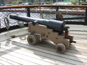
the example I was given is NOT a 8 inch Paixhan shell gun it is a carronade

We do not have any imagery of the specific Paixhans guns that were installed on USS Constitution in the 1840s. There were only a few of them used on Constitution, and I believe they were not modified from the standard design.
The link below is to a page in a French armament book describing the gun, and showing a couple drawings of it:

Caronadede_30_de_l’artillerie_de_la_marine_française.jpg

T3- d423 - Fig. 300. — Caronade de 30 de l’artillerie de la marine française.png
Fig. 300. — Caronade de 30 de l’artillerie de la marine française.

un axe passant par l’anneau rompu que l’on remarque à la partie inférieure et moyenne, A, en remplissait l’office.
Paixhans proposa de substituer à la vieille caronade un canon, dont il donna le modèle : c’était une pièce de grand calibre, montée sur un affût solide et de manœuvre facile. La figure 299, page 417, donne l’élévation de cette pièce. Elle n’a pas d’anses à la volée, mais une anse remplace le bouton de culasse.
En avant de l’affût on remarque un petit cric Α supportant un projectile ensabotté B.
Le recul de la pièce la faisant glisser sur les roues de l’affût devait amener la bouche de la pièce, juste en position pour que le cric élevât le projectile au-devant d’elle.
Ces canons pouvaient, au besoin, tirer le boulet plein, mais leur projectile ordinaire était la bombe. Leur épaisseur, en effet, n’était pas assez considérable pour lancer le boulet massif avec une forte charge de poudre ; la bombe était plus légère. Paixhans avait jugé que les projectiles explosifs devaient produire sur les vaisseaux un effet autrement redoutable que les boulets pleins, soit en déchirant largement la coque, soit en éparpillant leurs éclats dans les batteries ou les agrès.
Les expériences ordonnées par le gouvernement confirmèrent pleinement cette théorie et ces prévisions.

T3- d423 - Fig. 301. — Charge du canon obusier à la Paixhans.png
Fig. 301. — Charge du canon obusier à la Paixhans.
La figure 301 représente la disposition de la charge dans le canon-obusier à la Paixhans. Α est la gargousse pleine de poudre ; C, la bombe munie de sa mèche ; B, le sabot de la bombe ; D est l’âme du canon ; E le canal aboutissant à la lumière.
Le sabot de bois B servait à maintenir la bombe dans la même position pendant son parcours dans l’âme, à empêcher les mouvements de rotation
 
i found only one ship that actually might of had Paixhan gun and that was the USS Michigan built on the Great Lakes. Another account stated the ship carried Parrott guns.

this is a Parrott gun

parrott gun.jpg
 
Last edited:
An account of the guns carried by the Mississippi stated 8 inch Paixhan - type guns so whatever that means

i am thinking the Paixhan was the European version and the Dehlgren was the American version of the same type of gun

this is a Dahlgren gun which looks nothing like a Parrott gun

dahlgren gun.jpg

so far I have not found a Paixhan gun
 
Last edited:
The first columbiads produced in 1811 possessed a 7.25-inch (184 mm) diameter bore and took a fifty pound projectile. The army did not widely adopt early columbiads due to initial high costs of manufacture. Only after 1844 did an eight-inch (203 mm) model and a ten-inch (254 mm) model see mass production. The eight-inch (203 mm) columbiad could project a 65 pound shell 4,400 yards (4,000 m) or 4,800 yards (4,400 m) for solid shot; the model weighed 9240 pounds. The ten-inch (254 mm) columbiad weighed 15,400 pounds and hefted a 128 pound shell to 4,800 yards (4,400 m) or solid shot to 5,600 yards (5,100 m). These cast iron weapons were typically mounted on seacoast carriages designed to recoil up a slightly inclined set of "rails" or wooden beams. The mounted columbiad could pivot left or right on a traversing rail. In most cases the arc of pivot was less than 180 degrees, but some batteries allowed 360 degree traverse.[3] :61
Just prior to the American Civil War, ordnance officer Thomas Jackson Rodman developed an improved version of the columbiad, which became known by his name. Specifically the Rodman gun was designed to reduce cracking and other weaknesses found in such large iron castings. The process involved ensured the iron cooled evenly from the inside out, and resulted in what we might call today a "soda bottle" shaped casting with smooth, tapered exterior. The "Rodman" process also allowed the manufacture of much larger bore columbiads.
Between 1858 and the end of the Civil War, Northern foundries produced eight-inch (203 mm), ten-inch (254 mm), fifteen-inch (381 mm) and twenty-inch Rodman style columbiads. The smaller bore columbiads shared similar range factors to the older weapons, but the fifteen-inch (381 mm) models weighed over 25 tons and could fire 400 pound projectiles out to 5,000 yards (4,600 m). The monster twenty-inch model weighed over 60 tons but could range to over 5 miles (8.0 km). Very few of the largest types were built, and none were fired in anger during the war.

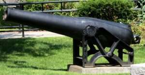
these are Columbiad guns it is possible these might of been on the Mississippi

columbiads guns.jpg
 
Thinking outside the kit box you can approach a modeling subject a number of ways. If you were to build this ship from bow to stern at 3/8 inch = 1 foot the model would be 7 feet long, but 3/8 scale would allow fine details. So you can build a cross section from the keel to the cap rail or go horizonal
and build a deck.

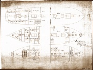
here is the location of the decks and their layout. The cabins were all Mahogany paneled with wainscoting

decks profile.jpg

Berth & Orlop Decks, hold.jpg
 
I was playing with the idea of building the structure of the deck in wood but use a transparent colored acrylic as deck planking. This way you see the planking but you can see through it to the beams and structure. Or build the cabins on top of the beams

forward Berth Deck.jpg
 
Last edited:
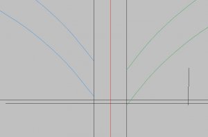
drawing frames from number 30 to 40 they are no longer drawn on the base line like frames 0 to 29 and this is why. The blue frame left of center is the position of frame 30 where it touches the black line it is above the base line it need to look like the green frame to the right. You can not move frame 30 down so you have to move the base line up.

frame 30.JPG

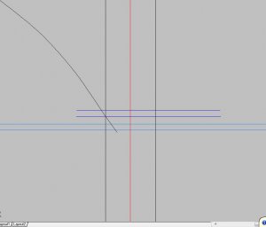
taking the light blue base line which is also the notch for the floors up to the dark blue position.

frame 30b.JPG

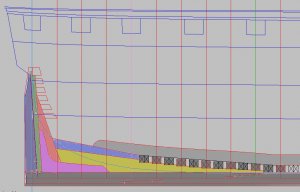
starting with frame 30 the angle of the floor becomes steeper and steeper so to set the frames a piece called the rising wood is used that is the yellow piece and you can see how it steps up as each frame reaches the stern.

rising wood.JPG
 
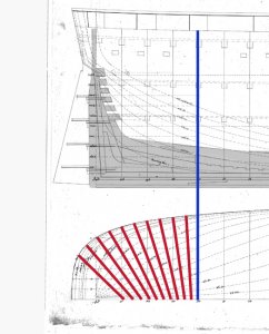
the blue line is frame 30 and is the last whole frame from frame 40 to the stern the floors are to steep of and angle so the frames become half frames that cant to the stern and are boxed into the side of the deadwood.

stern cant frames.jpg
 
Back
Top