Eric's Blandford Build

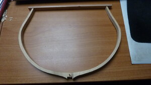
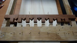
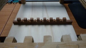
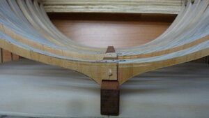
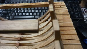
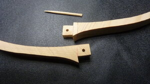
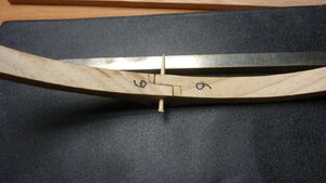
Finally got the remaining frames cut out today, two of the frame parts (of frames 1 - 5) will have to be re-sanded as they are a tad thick. The rebates on frame 6 took longer than anticipated (1.5 hours). The tooth pick in this photo is to lock the two halves together until the spreader bar has a notch cut in it to keep the frames at the correct shape then glue can be applied to the rebate.
I have figured out an easier way to cut the rebates but need to test it first.
P1010953.JPG
P1010954.JPGP1010955.JPG
 
Eric, looks really good, the first time I see the frames being made this way, exciting-
 
Hello and thank you Knut. Last year (I think) I received a Ryobi scroll saw for my birthday and started to cut out the parts for the frames, although I left plenty of wood around the small shapes the scroll saw blade would pull the pieces out of my fingers, so after trying various ideas settled on this. IF the timber was wide enough I would have cut the entire frame out. I stacked two pieces of wood together and cut the shape out on the band saw (using a 14TPI band). One frame from start to finish, including sanding - 45 minutes, sanding took the most time.
 
WEELLL! what the heck went wrong here??
The keel was taken from the the plans, taking into account the width of my frames and lined up with just frame 9 and frame 1, even 1 & 9 are not perpendicular to the jig. So, after scratching out what little hair I have left on the top of my noggin, I will now make keel #3 based on the spacing of my jig. AAARRRGH!

P1010956.JPG
 
Hi Eric!
There was a revision done to the keel by Mike in April 2018. I had problems fitting my frames to the keel notches so mike redid the keel. The final dimension for the keel length in the revision was 7-25/32" (not just over 8" as you mention). The problem was that the keel length called for based on the jig ( the old keel) was 7-27/32 i.e. 1/16" longer than the revision. Rather than remake the jig, I simply resized the revised keel by making it 101% of what Mike drew. The keel an frames fit the jig perfectly. Although the height of the keel was slightly changed, this did not end up causing any difficulty. See page 2 of my build log for my discussion about this. Here's the revised keel:
 

Attachments

  • Blandford_Keel-Keel 32 (1) revised April 2018.pdf
    216 KB · Views: 5
I do like your frame work, we each are learning how to do things slightly or more different than all the others.

This is your build, built the way you want to do it.
Hi Kurt,
Some years ago at a graduation I was referred to as "the thinking man's thinker" because I would look at a problem/task from all angles and then formulate a solution/task and then go with that (didn't seem to work here, did it?)
So, I have looked at it, brain stormed it and figured what needs to be done, go down to the hardware store and buy some timber, build a bridge and get over it. hahahaha. ROTF
Will post some pictures later today.
 
P1010958.JPG

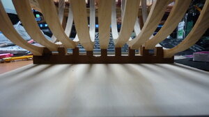
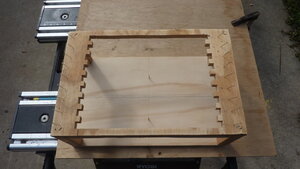
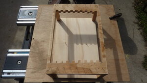
Two views of my jig, not the most professional looking one, but hey, it is only a jig. Base and top are plywood, the top is not the best looking plywood. The ply is made from plantation pine, warps one way if you sneeze and will warp the other way if you do something else.

P1010959.JPG
For those of a curious nature, the two lines in the base board, the one on the left is the actual centre of the base board, the one on the right is the centre of the keel/model, well it should be but it isn't. The centre of the model is the middle of frame #5.

P1010960.JPG

Here at least now my keel matches the build jig, I knew I'd get it right eventually (meanwhile a forest of cedar trees later....)
P1010961.JPG
 
Well, somewhere along the way it looks like "back to the drawing board" I will try and explain along the way...P1010962.JPG
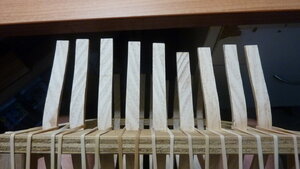
Frame #9 in the foreground, #8 the next one, both need their keel "seats" ton be cut out a bit more.

P1010964.JPG
Frame #2 (second one in) and its spreader, .5" gap.

P1010965.JPG
Frame #6, 4th from right is much shorter, traced and cut direct from plans, will study plans I think there is a gun port there.
 
Last edited:
With regards the second picture, the spreader bar was measured and cut from plans. As you notice I have rubber bands holding the frames back into the jig.
So I pose the question to myself, was the jig cut wrong? Just checked the height of jig supports and they are spot on, also checked spreader bar on plan and it is spot on.
So with all this analyzing I have come to this solution: I am going to leave it now for tonight and go and watch some comedy on TV and worry about it tomorrow, after all it is another day.
BTW my frame plans are dated '17
 
Eric, the frames on my model also have height differences that you also have, which you can see in my log, hope this can be adjusted at the end of the project, as this will be covered by planks, I hope, Knut-
 
Good to learn this stuff before I get that far in frames and now I won't have to worry that much.

I am assuming I will goof something up and have to worry about it at some point. It's called learning!
 
Sat outside this afternoon in the wind and cut some parts for my cross section, and sanded them BTW. Now that I have finally stopped sneezing I can now type this (got a huge headache by the way)

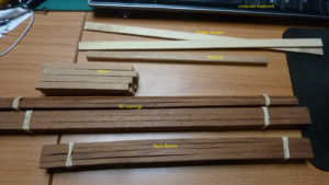
In the picture below all the timber pieces have been cut way oversize to allow for any imperfections in cutting and sanding.
The white timber is beech,
the keelson and pillars are oak,
the rest is red cedar.
The deck beams had the curve cut into them, the next two packs are NOT curved, just an optical delusion.
The keel has been sanded to be level with the top of the frames and soon they will be glued together and in place.
Forgot to include the strakes and deck supports which are a pinkish colour, will show them in the next picture/s
P1010978a.png
 
Thanks Mike, a friend of my youngest son has an antique furniture restoration business, he not only restores but also modifies and rebuilds all sorts of furniture. He gave me a small pile of offcuts. It has been almost difficult at times deciding what timber I can use where based on the quantity of a particular piece and getting the best cuts out of it. Depending on the next model you release and if I decide to build it, it will most likely be built entirely out of old flooring, which is quite hard and good quality pine.
I also have a 15" square piece of pencil cedar that I want to use on the model but haven't decided or figured out where best to use it, I had thought of perhaps using some for the hull planking.
Regards.
 
Hi Eric, the old flooring would be good for framing, it will be dry and stable. The cedar would make a nice-looking pump well room and shot locker It should be enough for the hull planking also.
 
Back
Top