FLYING DUTCHMAN

Dave Stevens (Lumberyard)

Sponsor: dlumberyard
Staff member
Sponsor
Joined
Dec 1, 2016
Messages
5,095
Points
728

Everyone just raved about the modeling skills of Mellpapa on the Black Pearl blog i will now present the build log of the Flying Dutchman by Mellpapa
once again Ship of Scale and our staff thank Mellpapa for graciously allowing the translation and posting of the build log.

flying dutchman1a.jpg
 
oh! you thought you were seeing the real thing, no, it is this a model
need I say more Mellpapa is a true artist


FD11-11-03-010.jpg

The blue sky finally came out and there was no wind, so I took another shot on the quay.
It's about 8:20 in the morning. There is no wind at all. The sky is blue and it is from the shooting date.
Immediately, I went to the same place I took the picture before and took a picture.
After taking a picture with the sea in the background, I made a mistake, but I made appropriate adjustments.

The stamp tool in Photoshop is a very useful tool.

I won't explain it in particular. Please enjoy the Flying Dutchman under the blue sky.

How I shoot it is like this.
All you have to do is fix it in Photoshop.

The place looks like this.
It was an outdoor shoot of the Flying Dutchman in the blue sky. How was that? There are many pros and cons.
But I was very happy because I was able to shoot under the blue sky.
 
like the Black Pearl the Flying Dutchman was another ship in the Disney movies and like the Black Pearl you can find pre built models to kits and toys from companies like ZHL to Lego you can also find a number of sources for drawings.
This drawing has no bodyplan so you would not be able to create a set of bulkheads. However, for a price you can find a working set of drawings.
I assume the same manufacturing and marketing applies to the Flying Dutchman as to the Black Pearl as there are many products available.

the-flying-dutchman-pirates-of-the-caribbean.jpg


as a final note because the last Blog of the Black Pearl is attacked by haters and bullies we have made it a point to work with organizations to prevent attacks on this or any other blogs we present on the forum. They are keeping a close watch and has flagged the haters. for hate talk and singling out people and businesses.
https://www.endcyberbullying.org/about-us/
https://us.ditchthelabel.org/

https://www.cybersmile.org/who-we-are
 
Last edited:
PART 1


FD09-10-18-01.jpg
It's a FLYING DUTCHMAN (FD) with very few materials, but I think that a hull can be made with just
this many drawings. …Is it true?
Well, I have to try it. Handrails, outfittings, masts and yard types can be made by thinking while
making the FD hull. The Black Pearl issue was made with that kind of feeling, so it will be manageable.
The drawings are still drawn with Illustrator 8.0. I don't have CAD or any other 3D software, so be
sure to use it. (Lol)


FD09-10-18-02.jpg
Production is started immediately. First, prepare a 5.5 mm thick cena veneer 1200 mm x 910 mm,
and trace the drawing on the left to this.


FD09-10-18-04.jpg
On the board, put the drawings that you printed out and joined together...


FD09-10-18-06.jpg
What to prepare...
Carbon paper, direct ruler, iron brush, free curve ruler, triangle ruler, cellophane tape after
mechanical pencil With this amount, you can trace.


FD09-10-18-07.jpg
And, it is the state where the trace is finished.
It will be convenient later in various ways if you trace the side view and the floor plan on the
same china veneer as the keel.
Printed paper drawings will expand and contract depending on humidity. So you can trace it to
China veneer. It's a bit of work, but it should be easier to make.
When we make the hull, we measure from this China veneer drawing...


FD09-10-18-08.jpg
Here, let's compare it with Black Pearl No. 2 boat whose production has stopped (laughs)...
It's big...


FD-Drawing-01.jpg
Next is this cina veneer cut.
 
PART 2

FD09-10-24-01.jpg
Now, let's cut the cena veneer. This is where the electric circular saw comes in!
Somehow... not a modeler, but a carpenter.


FD09-10-24-02.jpg
Check the cut line... I'm wearing blue work clothes, so I'm an old man in a construction shop.


FD09-10-24-03.jpg
Guys... I can't really like the sound of an electric circular saw. It's scary to hear this sound...
Cut out the keel.


FD09-10-24-04.jpg
With a plane, I will shape the cut cleanly. The use of an electric circular saw is awkward,
and the cut is rattling... (laughs)
Somehow... a carpenter... I'm wearing blue work clothes...


FD09-10-24-05.jpg
Next up is Bandsaw. It feels low and groaning, the sound is quieter and easier to use than an
electric circular saw.


FD09-10-24-06.jpg
Cut the frame part with a design knife!
I cut it carefully. Blue work clothes with white paint are wonderful! …Wonder?


FD09-10-24-07.jpg
Cut the frame part with a design knife!


FD09-10-24-08.jpg
Next up is Jigsou-kun... after all...


FD09-10-24-09.jpg
If you can't cut it with a band-saw, you can play around with a small turning knife.


FD09-10-24-10.jpg
The last turn is saw-kun. Fine cutting work is limited to this.


FD09-10-24-11.jpg
I'm cutting it with a guide wood. If you don't do this, you won't be able to cut straight...
It may be a little embarrassing... Pay attention to the hand holding the target tree. For some reason,
there is a white gumm around the base of the ring finger... It's cursed. The curse of modeling is cursing...


FD09-10-24-12.jpg

FD09-10-24-13.jpg
I managed to cut the keel. Ah! I forgot to take a picture of the sandpaper application...
Sorry for not being able to introduce Electric Thunder-kun.
In the photo on the right, A is the keel, B is the side view, and C is the workbench when making the hull.
D is a plan view. With this, even if the drawing on the paper is torn and disappears, it's OK!

Well, next is the frame. But that's all for today.
 
PART 3

FD09-10-25-01.jpg
The frame has been traced. I fell asleep when I was tired and I fell asleep... my eyes got tired.
Presbyopia makes this kind of work difficult...


FD09-10-25-02.jpg
It is a commemorative photo of China veneer and drawings.


FD09-10-25-03.jpg
It is a cutout of the frame. This is where the electric wire saw comes into play.
It sounds like a sewing machine. It's cutting smoothly.


FD09-10-25-04.jpg
It is a close-up photo. It is cutting out smoothly...
You can see the hands that are sick.


FD09-10-25-05.jpg
If you cut it into smaller pieces... Woo!
that? The arm of the saw does not move, only the sound of the motor turning… Shwi~~~~~
Is it broken? !! What's wrong? Turn off the switch, hold the saw, and shake it to make a strange noise.


FD09-10-25-06.jpg
When I disassembled the back of the saw, what! The gear that moves the arm is cracked... Allya
Finished...
Tomorrow, I'll go to the shop where I bought it and order parts.
I could not give up the work, so I cut it out using a band saw. Also, there are 7 left, but today's work is over.
The picture on the left shows today's achievements... I still have some tweaks, but I'm tired.
 
PART 4
FD09-10-26-01.jpg
Yesterday, it is a broken electric wire saw. The red circle is a part that has been cracked.
I wonder what it is, because it's a cheap product made of ○○. However, I went to the construction shop to order parts,
saying, "Did you do your best in that way?" Once repaired, they will play an active role again.


FD09-10-26-02.jpg
* The next day, there is a phone call from the construction company, and the parts arrive about 12th of November.


FD09-10-26-03.jpg
It is an enlarged photograph of a part that has been cracked.


FD09-10-26-04.jpg
Once again, it's time for Bandsaw. Cutting the remaining 7 sheets. I thought it would be better to cut it off roughly,
but no, this is quite easy to do. It also cuts curves nicely. It's a straight cutting blade. It cuts reasonably and cleanly.
No, I reviewed it. Band saw with straight cutting blade. I'll buy you a curved cutting blade next time. The number of
appearances will increase more and more.
Band saw was such a good thing.


FD09-10-26-05.jpg
If it's a cut tree or a plastic model, is it thick Bali? (Lol)


FD09-10-26-06.jpg
After using it, open the lid and clean it.
It's a ritual after using the tools. When you use it next time, you can use it comfortably. Of course,
I will check if there is any slack.

FD09-10-26-07.jpg
This is the finished frame. I will take a commemorative photo with Keel.
It was late at night because it was work after finishing work and ordering parts and then having dinner.

It's too early for time to stand. I still want to do it, but tomorrow's work should not be affected, so this is it for today.

I will fine-tune the frame from tomorrow.
 
BUILDING THE HULL 1A


FD172-001-001.jpg
1/72 Flying Dutchman craft.
Trace down the keel frame using 4mm thick veneer.
Cut out using a band saw or electric saw, and fix the temporary assembly.


FD172-001-002.jpg
After gluing the keel frame, put the filler on the bottom of the ship.
The material of the filler is the cheapest Falcata material in the home improvement center.
The aerial veneer in front is printed with a side view above the waterline.
Printed with an inkjet printer. Any inkjet printer that can print on thick paper can print.


FD172-001-003.jpg
It looks like this from the bow.
I'll add plenty of filler!


FD172-001-004.jpg
Fill the stern with filler.


FD172-001-006.jpg
Licking angle from behind...


FD172-001-007.jpg
And a little more...


FD172-001-008.jpg
After filling the filler, shape the bottom of the ship with an electric sander.


FD172-001-009.jpg
It is a work place behind the garage. This band saw played a big role.


FD172-001-010.jpg
It is the foundation of the outer plate. I'm using aviation veneer 0.6mm thick.
The aviation veneer printed with an inkjet printer is cut out with a cutter and stuck from the stern.
Tight bond is used as the adhesive.
It's right and left simultaneous.


FD172-001-011.jpg
Glue the second piece.


FD172-001-012.jpg
Also on the other side.


FD172-001-013.jpg
While adhering the third sheet...


FD172-001-014.jpg
While the other side is also glued...


FD172-001-015.jpg
More and more side panels are stuck, and it's a little more.


FD172-001-016.jpg
On the other side too!


FD172-001-017.jpg
I finally pasted it.


FD172-001-018.jpg
I pasted the other side as well.


FD172-001-019.jpg
Side photo to commemorate.


FD172-001-020.jpg
A memorial photo of the ship bottom.


FD172-001-023.jpg
And the photo from above.


FD172-001-024.jpg
I prepared the bow part using balsa wood.
The hull was trimmed by using an electric sander to trim the step created by aviation veneer to shape the hull.
This completes the groundwork for attaching the outer plate.


FD172-001-025.jpg
Stem and beak head.
This is also a little work done and combined.

As you can see, I carved the stem side so that the beak head can be fitted exactly.
By the way, the stem is 4mm wide and the beak head is 2.5mm thick.
 

Attachments

  • FD172-001-005.jpg
    FD172-001-005.jpg
    55.5 KB · Views: 11
Last edited:
BUILDING THE HULL 2A

FD172-02-001.jpg
The bow deck is attached with 1 mm thick and 3 mm wide cypress. And the front wall of the bow tower
is made of the same material as the deck, and the lower part is stuck and drying.


FD172-02-002.jpg
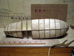
The red arrow and prismatic material are temporarily attached to the keel part of the foreclosure.


FD172-02-003.jpg
Also on the poop keel part. I'm temporarily adhering a prismatic material to the red arrow.


FD172-02-004.jpg
This is so that the aviation veneer on the side will not be damaged if turned upside down.
Remove the outer plate after attaching it.


FD172-02-005.jpg
Since the cypress wood stuck on the front wall of the foreclosure is not yet dry,
I will stick the garboard strike.


FD172-02-006.jpg
It's easy to paste because there is a filler in the bottom of the ship.
This is the bow side.


FD172-02-007.jpg
This is the stern side.


FD172-02-008.jpg
While waiting for the Garboard Strake to dry, use a baby food bottle to soak the front wall
of the foreclosure in water, put it on the bottle, fix it with masking tape, and dry.


FD172-02-009.jpg
When the cypress is dried, remove the masking tape and the material will be finished along
the curved surface of the glass bottle.
Stick this on the front wall of the foreclosure.


FD172-02-010.jpg
It looks like this! It's messy with the tight bonds protruding, but it's beautiful when
sandpaper is applied!


FD172-02-011.jpg
I cut off both ends of the wall material and applied sandpaper to clean it, but this is the Flying Dutchman,
so I immediately put in grain of grain.


FD172-02-012.jpg
I also attached a second skin from Garboard Strike.
Once this is dry, sandpaper it and glue the keel.


FD172-02-013.jpg
Since the tight bond has dried, I pierce the step with a plane and sandpaper to make
a hole for screwing the keel.


FD172-02-014.jpg
It is a screw for screwing the keel, but the diameter of the head part is about 4 mm.
I used a grinder to cut it to a diameter of about 3 mm.


FD172-02-015.jpg
Align the screw with the keel and try temporary assembly.


FD172-02-016.jpg
Since the temporary assembly looked good, I used a tight bond to bond it and tightened the screws.


FD172-02-017.jpg
Continue to tighten the screws. The screw was a little too long...
I'm tired.


FD172-02-018.jpg
It looks like this when you finish tightening the screws.
I will cover it with a wooden plug later.


FD172-02-019.jpg
Make sure you have an accurate baseline before applying the skins to the hull.
Since the side view printed on a flat surface is directly attached to the side surface
of the three-dimensional hull, the line naturally goes crazy.
Then, I will make a dedicated stand and draw accurate lines with a pencil.
 
FD172-02-020.jpgFD172-02-021.jpg
The red line is a side view printed on the airline veneer.
The vertical line of the pencil is an accurate line drawn by measuring from the drawing.


FD172-02-022.jpgFD172-02-023.jpg
When you have an accurate vertical line, draw the line of the reference plate.
Use the self-made Toscan to mark the position of the reference plate on each vertical
line and connect the points to form the reference plate line.


FD172-02-024.jpg
It is a little crazy at the bow.
The pencil line is the accurate line for the time being.


FD172-02-025.jpg
This is getting crazy in the part near the stern.
So why did you stick the printed veneer?
I wanted to make a rough shape on the side... (;^ω^)b
Now you are ready to attach the outer reference plate.
 
View attachment 165106View attachment 165107
The red line is a side view printed on the airline veneer.
The vertical line of the pencil is an accurate line drawn by measuring from the drawing.


View attachment 165108View attachment 165109
When you have an accurate vertical line, draw the line of the reference plate.
Use the self-made Toscan to mark the position of the reference plate on each vertical
line and connect the points to form the reference plate line.


View attachment 165110
It is a little crazy at the bow.
The pencil line is the accurate line for the time being.


View attachment 165111
This is getting crazy in the part near the stern.
So why did you stick the printed veneer?
I wanted to make a rough shape on the side... (;^ω^)b
Now you are ready to attach the outer reference plate.
Dave
I read your Black Pearl blog and this one, I learned a lot. the process is very impressive The working methods .
I will try to apply in the construction my ship's.
 
ever since the plank on bulkhead kits, construction to solve the space between bulkheads was to double plank the hull. By doing this it gives the builder a solid surface for the finish planking.
If you leave the space open between the bulkheads the planking will not lay proper to the shape of the hull. Buildes now fill in the space with filler blocks of wood or a dense foam board.

What Mellpapa did was to fill the bottom half of the hull with Balsa blocks and skin over the upper section with aircraft plywood. This is quite an innovative way to get the hull shape without spending all the time planking twice.

Mellpapa's way produces a very strong and stable hull
 
Back
Top