FLYING DUTCHMAN

Staying of deck materials part 13A


FD1-72-13-01.jpg
Stern deck 001
I put a cypress material with a thickness of 1 mm and a width of 3 mm. It is a little
troublesome that the margin plank part does not fit well.

FD1-72-13-02.jpg
Stern deck 002
I stuck the same material as stern deck 001.
It is uneven because it does not have sandpaper.


FD1-72-13-03.jpg
Since the stern deck 001 and the stern deck 002 have been pasted, two are taken
together and it is a commemorative photo.


FD1-72-13-04.jpg
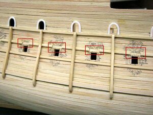
This is a photo of the stern deck 003 being stuck.


FD1-72-13-05.jpg
I managed to stick three.
Since the surface is uneven, I applied sandpaper after this.


FD1-72-13-06.jpg
When you have finished applying the sandpaper, use the usual tools to add wood grain.
It's a strange story to put wood grain in a tree (;^ω^)b


FD1-72-13-07.jpg
I will scratch it like this and add wood grain.


FD1-72-13-08.jpg
FD1-72-13-09.jpg
FD1-72-13-10.jpg
Although it does not fit on a scale, I think that if you paint like this, if you smear and stain it,
it will come out as sharp as it is. ……(;^ω^)b


FD1-72-13-11.jpg
So, I finished inserting wood grain for all three stern decks.
 
PART 14A

FD1-72-14-001.jpg
I was wondering if I should make the beam arm that supports the deck on the hull side,
but I decided to make the scary face of the gun gate.
Therefore, I cut the extra mall part. It's the red line.
This is a photograph of the Port Quarter Gallery and the port stern breech gate.


FD1-72-14-002.jpg

FD1-72-14-003.jpg
This is a picture of the port bow.


FD1-72-14-004.jpg
Cut off each gun gate molding part.
The starboard side also cuts a hamper to make faces.
It's a mall just around the nose of your face.
This is the bow side.


FD1-72-14-005.jpg
This is the starboard quarter gallery and the stern gun gate side.


FD1-72-14-007.jpgFD1-72-14-008.jpg
All malls that do not need port or starboard have been cut.
 

Attachments

  • FD1-72-14-006.jpg
    FD1-72-14-006.jpg
    57 KB · Views: 4
Making the gate face part 14A


FD1-72-14-009.jpg
I make a face, but the materials are epoxy putty, polyester putty, Tamiya putty, oil clay,
paper clay, wood powder, plaster, etc.
There are various, but I use Daiso's wood powder clay and instant adhesive for wood products.
All you need is a toothpick!


FD1-72-14-010.jpg
Here are two recipes.
First, the first.
I'll put wood flour around the gun gate.


FD1-72-14-011.jpg
Poke with a toothpick and shape it into a face.
When it becomes a face, apply an instant glue for wood products and harden the wood powder clay.
It will harden tightly.


FD1-72-14-012.jpg
And it is in a solid state.


FD1-72-14-013.jpg
Second.
This is a method of making wood flour clay while partially filling it.
Wood flour clay is laid on the top of the face first, and a face is created by poking it with a toothpick,
and then clay is laid on the vertical and lower parts of the mouth to create the face.


FD1-72-14-014.jpg
I use the bottom of the toothpick to add texture.


FD1-72-14-015.jpg
For the beard of the jaw, use the tip of a toothpick.


FD1-72-14-016.jpg
When you are ready, apply an instant adhesive for wood products and use a toothpick to further
condition your face until it dries.


FD1-72-14-017.jpg
It looks like this when the instant adhesive dries.


FD1-72-14-018.jpg
FD1-72-14-021.jpg
I made scary faces on both the starboard and port sides.
I put the face number on the starboard side image, and put the enlarged image with the
corresponding number below.


FD1-72-14-019.jpg
It's difficult to make a face.
It doesn't look like the real thing at all...(;^ω^)b


FD1-72-14-020.jpg
This is the port side.
Like the starboard, I put the face number in the image and put the enlarged image with the
corresponding number below.


FD1-72-14-022 (1).jpg
This is a real image.
It doesn't look like...
I'll touch you... (;^ω^)b
The model is an atmosphere.
Kanben~
Forgive me~ (^▽^;)b

Today is up to here. How about making scary faces on both sides of FD? Does not look like! After all...
As I wrote above, the atmosphere is... (;^ω^)b
 
PART 15A

FD1-72-15-001.jpg
It is Proxo's mini router MM30 No.26800.
I'll use this guy to cut out the stern window frame.


FD1-72-15-002.jpg
I will make a lot of holes like this.


FD1-72-15-003.jpg
Drilling of the lower window frame is finished.


FD1-72-15-004.jpg
Next, I will use a craft knife to cut and tear off.


FD1-72-15-005.jpg
The hollowing is completed.


FD1-72-15-006.jpg
The lower window frame will also be stripped and cut.


FD1-72-15-007.jpg
This completes the hollowing of the upper and lower window frames.


FD1-72-15-008.jpg
I cut the cut out with a craft knife neatly with a design knife.
 
Window frame production part 15A


FD1-72-15-009.jpg
I will do it with the same method as when I made it with 1/60 FD issue.
The outer frame is manufactured first. The top and bottom are made of cypress wood with a thickness of 1 mm and a width of 2 mm.

FD1-72-15-010.jpg
First, cut a groove of about 1 mm in the center of the horizontal frame with a circular saw,
and vertically glue a cypress material with a thickness of 0.5 mm and a width of 2 mm.


FD1-72-15-011.jpg
Use a circular saw to cut the groove that inserts the vertical frame to the left and
right of the vertical frame that was placed in the center.
Grooves are carved in the horizontal and diagonal frames.
I'm using a 0.6mm thick circular saw blade.
By the way, circular saw is Proxon's mini circular saw.


FD1-72-15-012.jpg
Assemble the stand frame with cypress wood of 0.5mm thickness and 2mm width.
It's very difficult to do because the things are small.


FD1-72-15-013.jpg
I managed to incorporate a stand frame. However, the position of the standing frame
of both window frames at the bottom was a little crazy. How tough it is...
I have no intention of recreating it, so I will continue with it.
If you put a horizontal frame, it will be unnoticeable.


FD1-72-15-014.jpg
I made it by incorporating the horizontal frame of the triangular window frame. It's small,
so it's quite difficult.
This is enough for a triangular window frame.


FD1-72-15-015.jpg
The trapezoidal window frame below also incorporates a horizontal frame.
But this is a little... The small window is distorted.


FD1-72-15-016.jpg
It's distorted... It's distorted and the small windows aren't the same size...
Hmmmmmm...
I will remake it. If it is the same as this, it will be distorted again, so try changing the method.
Make the middle frame first, cut the top and bottom, and cut the left and right diagonally.
Stick the outer frames on the left and right... Let's do it like this!
 
Production of trapezoidal window frame part 15a


FD1-72-15-017.jpg
Trim the ingredients with a chopper. I'm using cypress wood of 0.5×3×900 mm.


FD1-72-15-018.jpg
The width of the cut material is cut to 2 mm.


FD1-72-15-019.jpg
Align the trimmed vertical frame materials and adhere the red line part with a tight bond.
Do the same for the material of the horizontal frame.


FD1-72-15-020.jpg
Make a grid with a black border and a red border on your computer and print two of them.
Cut out the blue frame of the first printed sheet.


FD1-72-15-021.jpg
Cut out the green frame from the second printed sheet.

FD1-72-15-022.jpg
Glue the cypress with the horizontal frame to the paper with the blue frame cut out
[Adhere only on both sides. ]
The cypress, which is a vertical frame, is attached to the paper with the green frame cut out.


FD1-72-15-023.jpg
The groove can be evenly cut by aligning the red line with the path of the saw blade and
sliding it on the slide table of the Mini Saucura.
The mini saw Curacao circular saw blade has a thickness of 0.6 mm and extends 1 mm from the slide table,
resulting in a groove with a depth of 1 mm.


FD1-72-15-024.jpg
It is a close-up image in the middle of making a groove.
You can see that the circular saw blade protrudes 1 mm from the slide table.


FD1-72-15-025.jpg
A groove was engraved on the vertical frame material. It’s just right.


FD1-72-15-026.jpg
This is a horizontal frame material. The groove has been cut. The grooves are also uniform here.
There is no precise feeding tool, but this way you can evenly cut the groove.
It is an application when making grating.


FD1-72-15-027.jpg
When the grooves are cut, the materials that have been bundled are separated to combine vertical
and horizontal materials.


FD1-72-15-031.jpg
Done!
The small windows are now evenly framed.


FD1-72-15-028.jpg
Cut the protruding material with a chopper!


FD1-72-15-029.jpg
Chopper is wonderful!


FD1-72-15-030.jpg
Cut left and right diagonally with a mini circular saw.


FD1-72-15-031.jpg
Glue the frame material to the diagonally cut part and cut the protruding part.
The frame material that protrudes above is cut.


FD1-72-15-032.jpg
I compared it with the window frame I made earlier.
The right side is the newly remade window frame.
It’s better than before.
I'm a little dissatisfied though.


FD1-72-15-033.jpg
It is an up image. The dissatisfaction is that the left and right diagonal cuts are slightly misaligned.
Well, right


FD1-72-15-034.jpg
I tried to temporarily assemble it on the hull.
It looks like this.


FD1-72-15-035.jpg
By the way, the size of the window frame I made this time is like this compared to a 10-yen coin.


Today is up to here. It was work on the window frame of the stern, but it does not work very well.
When I made the same method as the 1/60FD issue, it failed brilliantly. If the size is different,
you have to change the making method. There are times when I'm sneaky... Tehhehe (;^ω^)b
 
Crafting of the bow part 16A


FD1-72-16-001.jpg
I made a drawing of the scary face of the triple cannon on the bow.
Based on this, make one with epoxy putty, mold with silicon and duplicate two with resin.
Printed out above.


FD1-72-16-003.jpg
I printed it out, partially cut it, and attached it to the bow with masking tape.
Since the position has been decided, trace down this.


FD1-72-16-004.jpg
When I trace down, it looks like this.


FD1-72-16-005.jpg
I cut out the mouth part.
This is the end of the processing on the hull side.


FD1-72-16-006.jpg
Do not make a scary face directly on the hull, but on a transparent plastic plate using epoxy putty.
Place a transparent plastic plate on the drawing and secure it with cellophane tape.
Tamiya Epoxy molding putty creates a scary face relief for a triple cannon gun.


FD1-72-16-007.jpg
Looking at the illustration on the right, I made the face on the left.


FD1-72-16-008.jpg
It is a close-up image. Once it's cured, mold it with silicone and duplicate it with resin.


FD1-72-16-009.jpg
Make a wall from clay and pour in silicon. This is OK because it is a duplicate of only one side!


FD1-72-16-010.jpg
About 20g of silicon was poured.
It is left as it is overnight.


FD1-72-16-011.jpg
The next day after being left overnight, the silicone will solidify and replicate with the resin.
Original shape and commemorative photo.
Silicon was flying white...


FD1-72-16-012.jpg
So, one copy at once. I was able to do it well.


FD1-72-16-013.jpg
Continuously duplicate the second one. This was also successful, so the replication is finished.


FD1-72-16-014.jpg
Then, I stuck it to the bow with instant adhesive.
As it is, there is a feeling of strangeness, so I will put the putty on it and make it familiar,
but this is it until today.


It was a scary face work on the bow. I'm tired today.
 
Bit and fife rail part 17A

FD1-72-17-01 (1).jpg
It is a bit production. Since there is no 4 x 4 mm square bar, 2 x 4 mm plate materials are
stuck together to create a 4 mm square bar, cut into the shape of a bit, then wood grain is added,
the surface is roughened, and then it is glued to the deck.
The picture is a bit of foremost. It's not vertical, but it's vertical. It appears to be slanted
due to the distortion of the wide-angle lens of the camera.


FD1-72-17-02.jpg
It is a picture with the position changed.


FD1-72-17-03.jpg
As you can see on the back side, the bits are not removed.
It's a combination of convex and concave.


FD1-72-17-04.jpg
This is the bit on the side of the Mizun mast.


FD1-72-17-05.jpg
A picture with the position changed.


FD1-72-17-06.jpg
This is also a picture with the position changed.


FD1-72-17-07.jpg
It is the back side. It is glued with convex and concave processing so that it does not
come off like the bit of fore mast.


FD1-72-17-08.jpg
It is the production of fife rails. I use a plate material with a thickness of 1 mm and a width of 4 mm.


FD1-72-17-09.jpg
I glued it to the bit on the mist mast side.


FD1-72-17-10.jpg
Let's tentatively assemble the deck on the hull.
It looks like this.


FD1-72-17-11.jpg
This is a fife rail glued to the bit on the fore mast side.


FD1-72-17-12.jpg
It is a temporary deck assembly.


FD1-72-17-13.jpg
It is a picture with different angles.
It looks like this.
 
Belay pin PART 17A


FD1-72-17-14.jpg
A toothpick is used to make the belay pin. We prepared a toothpick for Daiso.
There is no need to use expensive toothpicks, and belay pins are sold at sailing boat
model shops as parts, but making them with toothpicks is cheap...
So I will make it by shaving the toothpick.


FD1-72-17-15.jpg
This is a sharpened part of a toothpick. I will make it using this part.


FD1-72-17-16.jpg
Cut the tip like this...


FD1-72-17-17.jpg
Next, cut the brim...


FD1-72-17-18.jpg
Shaving the mochi hand part...


FD1-72-17-19.jpg
Cut off the part of the mochi part that is rounded.


FD1-72-17-20.jpg
This is about the size of my index finger.


FD1-72-17-21.jpg
Then, we will mass-produce it without separating it.
If you cut them off, there is a risk that they will be gone, so when you have the number, cut it at the end.


FD1-72-17-22.jpg
It looks like this when cut.
No! It looks like a belay pin...(;^ω^)b


FD1-72-17-23.jpg
I've glued it to the Mizen Mast fife rail.
It looks like it, right?
I will make the fore mast and main mast belay pins.
Patience is all you need to make many of the same things.
It does not require guts or effort.


FD1-72-18-001.jpg
I made a foreground belay pin, so I glued it.
The shape of the belay pin wasn't the same, but if it doesn't look strange, it's good.


FD1-72-18-002.jpg
This is the main mast belay pin.
If there is no sense of incongruity in appearance, it is considered "good" again. I'm using a tight bond.


FD1-72-18-003.jpg
It is a belay pin of the main mast that changes the shooting position.
It didn't change compared to the picture above. Tehhe...


FD1-72-18-004.jpg
This is a mizzenmast belay pin that I made and posted a photo of last time.
Foremost main mast. The fake rail and belay pin are also necessary for the mizzenmast bulwark,
but these are built when making the bulwark.


Finally, the production of FD1/72 is restarting. I left it for quite a while. If you leave
it for a while and resume production, the work feels fresh for some reason.
If you keep making it, you get tired of it, and if you get tired of it completely,
you can't finish it. So I have to take a break in a suitable place.
 
Last edited:
Quarter Gallery PART 18A


FD1-72-18-005.jpg
I cut out the upper and lower pedestals of the Quarter Gallery and matched them with the hull.
It takes a lot of time because it is gradually scraped to match the curve of the hull wall at the stern.
This is the starboard side.


FD1-72-18-006.jpg
This is the port side.
The starboard and port walls are not subtly symmetrical. So it's a shame because it's a
little shaving to match each hull wall.


FD1-72-18-007.jpgFD1-72-18-008.jpg
A photo seen from above and a photo seen from behind. We will make each block of the quarter
gallery with balsa wood according to this stand.


FD1-72-18-009.jpgFD1-72-18-010.jpg
However, the board of the table seems to be a little thin. I used 3mm thick agatis material,
but when I look at the drawing, it is close to 4mm thick...


FD1-72-18-011.jpg
Therefore, a 1 mm thick cypress material was attached under a 3 mm thick base to a thickness of 4 mm.


FD1-72-18-012.jpg
Production of each block. While tentatively assembling, shave the balsa wood to create a shape.


FD1-72-18-013.jpg
This is a balsa material that has been cut out to make each block.


FD1-72-18-014.jpg
I have to make the left and right shapes the same.
It's quite difficult.


FD1-72-18-015.jpg
I'm cutting off like this. I'm not using difficult tricks.
I'm just cutting with a cutter.


FD1-72-18-016.jpg
This block looks like a "pine cone".
Just scrape it...


FD1-72-18-017.jpg
I managed to make two "pine cones".
It's the "pine cone" at the top of the Quarter Gallery.
The bottom row requires four "pine cones".


FD1-72-18-018.jpg
I also made a roof part by adhering the "pine cone" in the upper tier to the base.
It looks like this. I'll put a texture like "pine cone"...
That's all for this time.


Quarter Gallery is quite tough... Especially "pine cone" is tough. But it will take some time, but it will be manageable.
 
Last edited:
a few years back i was at a model ship conference where i had a vendors table. I could hear a conversation between two attendees discussing what wood to use for model ship building. The one person said "oh you have to use Boxwood it is the only suitable wood for model ship building"
Later that day the second person came back to the table looking for Boxwood which i happen to have. He said he wanted to build a framed model but the price of Boxwood was way out of his budget, i suggest several other woods to use but he was just not sure because he was told you have to use this or that wood.
The point is making such blanket statements like you HAVE to use this wood is just not true.
Mellpapa in the last post is using Balsa wood and he is building a world class model. If i would suggest Balsawood or Basswood at the conference i would have been shown the door. so being a wood dealer i give them what they want expensive exotic wood.
A choice of wood and materials depends on what you want to achieve in the final results, if you want a wood that polishes like stone then Boxwood is a good choice. If you are painting the part it really does not matter.
 
Quarter Gallery PART19

FD1-72-19-001.jpg
I made two "acorns" just before the "pine cone" in the lower part of the starboard rear quarter gallery.


FD1-72-19-002.jpg
I added the texture of the upper roof part of the starboard rear quarter gallery.
I just cut it with a cutter...


FD1-72-19-003.jpg
It is a shooting from the front side.


FD1-72-19-004.jpg
Then, I put "acorn" again.
What should I do next?


FD1-72-19-005.jpg
Observe from the front.


FD1-72-19-006.jpg
Observe from behind.


FD1-72-19-007.jpg
The "acorn" on the port side was also carved out. I will carefully observe it and continue to shave it,
but it is confirmed that the shape of the "acorn" is correct.


FD1-72-19-008.jpg
Put the end of the exit with a pencil in the red acorn "Acorn".


FD1-72-19-009.jpgFD1-72-19-010.jpg
Enlarged photo of the left and right "acorns"


FD1-72-19-011.jpg
Engrave the exit of the "Acorn", paint the inside black and engrave the texture of the "pine cone".


FD1-72-19-012.jpgFD1-72-19-013.jpg
The picture was taken from an angle so that you can see the "pine cone" better.
The "pine cones" on the left and right have fallen apart...
I'll fix it with epoxy putty later.


FD1-72-19-014.jpg
The lower part of the roof and the base of the quarter gallery on the rear of the port were carved out.
I cut out the “pine cone” part to match it, but this is difficult. I used Tamiya's epoxy putty to fill
the gaps.
I thought there was a stock of epoxy putty for woodworking, but I didn't look for it and instead
I had Tamiya's epoxy putty, so I used it.


FD1-72-19-015.jpg
Shooting from behind.


FD1-72-19-016.jpg
This is a picture taken from the front.
Quarter Gallery is still going on.


The Quarter Gallery is too tough... but it's quite like that if you take the time.
Then, I'll do my best until the completion! …(;^ω^)b
 
After finishing Aragosy- Ragusian Carrack this is my next build. Plans 1:1 are already hanged on my wall and bulkheads prints prepared to be glued and cut.

It will be a huge project because Melpapa's drawings are very basic in essence and all details must be worked out during the build. That would be addition to my previous project- Black Pearl finished in October 2019


with you also taking on this built it would be wonderful if you did a build log and your work and details can be added to Mellpapa's work. This is what this international forum is all about sharing information and helping one another.
Mellpapa is in Japan you are in Serbia but everyone is here.
Mellpapa offers his plans of the Black Pearl and the Flying Dutchman free to anyone, what an honorable thing to do!
 
So true Dave. I was treated the same exact way back in my serious plastic model building days....

Mike Shanks


that is the backbone of progress people who do not pay attention to the nay Sayers and forge ahead. when you told hey you can't do this or that but you say oh ya just watch me. you break new ground, introduce new ideas, forever advancing and we all advance.

just do it
 
hey you can't do this

That is kind of what I am doing in my llittle Nina build. Yes Im sure some expensive woods would make the decks look better but I
used craft store junk meant for kids and it actually came out pretty good. Yes I want you guys to give me your opinions and
guidance but ultimately it's up to me and what I can afford to do the model to my best ablity.
 
Quarter Gallery part 20


FD1-72-20-001.jpg
The roof under the quarter gallery on the starboard side is carved and glued.
I cut down the terraced fields of the roof.
Gradually step down the field.
You don't have to engrave it neatly. Rough is enough because I will make fish objects with putty on this.
Even if it is rough, the foundation must be made properly... (;^ω^)b


FD1-72-20-002.jpg
Check from the front...
Isn't it strange?


FD1-72-20-003.jpg
Check from the bottom...
I found a part that was not engraved and carved it.


FD1-72-20-004.jpg
The terraced fields below the quarter gallery on the port side are also carved out,
and the terraced fields are carved into the lower side as well as the starboard side.


FD1-72-20-005.jpg
Also check from the front!


FD1-72-20-006.jpg
Also check from the bottom!
It's about getting better.


FD1-72-20-007.jpg
Seen from behind, I was able to manage the left and right... ?


FD1-72-20-008.jpg
It is up from the back.
Somehow, it seems that it was targeted for left and right.
There are some strange things, but I don't care about the details...
By the way, my blood type is O type.
(;^ω^)b


FD1-72-20-009.jpg
The stern gallery's terrace is carved out of balsa wood and is a temporary assembly using brass wires.
Upper and lower two steps How about this? ?
Well, it looks like this.


FD1-72-20-010.jpg
A view from the side. The position is also like this.
This is quite appropriate.
 
Back
Top