FLYING DUTCHMAN

part 20


FD1-72-20-011.jpg
Deck material was struck on the upper terrace. It is a 3 mm wide 0.5 mm thick cypress.


FD1-72-20-012.jpg
I put the outer plate material on the mask on the upper terrace. It is a 1 mm thick cypress
with a width of 5 mm.


FD1-72-20-013.jpg
I am putting a decorative board on the side of the terrace above.


FD1-72-20-014.jpg
Next, on the terrace below, we also applied deck boards, outer boards, and side panels.
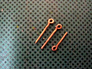


Handrail support


FD1-72-20-015.jpg
I will shave from 2×2×91 mm cypress lumber.


FD1-72-20-016.jpg
Scrape the lower part of the pillar……


FD1-72-20-017.jpg
Next, trim the upper part of the pillar to shape it


FD1-72-20-018.jpg
Completed by separating... Repeat this [sweat]


FD1-72-20-019.jpg
When about 6 pillars were made, the pillars were positioned on the terrace side.


FD1-72-20-020.jpg
It's an expansion of 6 struts. Since we will build it from the terrace above, we need about 9 more.


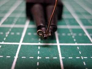
Handrail construction on the upper terrace


FD1-72-20-021.jpg
When the pillar is made, load the brass wire...


FD1-72-20-022.jpg
Set up the pillars on the terrace.


FD1-72-20-023.jpg
I have set up all the columns.


FD1-72-20-024.jpg
Underlaying of the handrail. It is working with the actual product using a 0.6 mm aviation veneer.
So there is no drawing.


FD1-72-20-025.jpg
After finishing the underlaying of the handrail, attach a decorative plate (cypress cypress 0.5mm thick)
on it. First of all, from the center railing...


FD1-72-20-026.jpg
When the middle is finished, paste both sides.


FD1-72-20-028.jpg
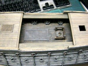
It is completed after finishing the veneer. I want to see the horns at the four corners,
but I will make it after the lower terrace part is made. It's a little distorted, but I don't care (laughs)


FD1-72-20-029.jpg
A view from the side.


FD1-72-20-030.jpg
This is the view from below.


That's all for this time.
I stopped working from FD1-72-19 .
It is finally time to resume work.
Next is a large terrace with a terrace.
I wonder how many posts have to be cut out?


I interrupted my work and worked a lot. Photo shooting, video shooting, package design, etc.
Finally, after finishing my work, I will resume production of the FD issue.
 
Production of the terrace (larger) under the Stern Gallery PART 21


FD1-72-21-001.jpg
It is the same as the small upper terrace made earlier.
I hate it because there are a lot of stanchions. Good luck with mass production.
About 31 including the spare. (2 spares)


FD1-72-21-002.jpg
Drill 29 holes with a pin vise to charge 0.5 mm brass.


FD1-72-21-003.jpg
Now that I have finished with the brass, I will stick it on the terrace.
The horns are amazing.


FD1-72-21-004.jpg
Prepare the handrail. First from the center. I am using a 0.6mm aviation veneer.


FD1-72-21-005.jpg
Make the left and right from the center.


FD1-72-21-006.jpg
Right and left are done.


FD1-72-21-007.jpg
When the adhesive dries, cut off the protruding posts with nippers.


FD1-72-21-008.jpg
The left and right handrails are prepared.


FD1-72-21-009.jpg
A cypress wood of 0.5mm thickness is pasted on a 0.6mm aviation veneer to finish the shape.
It is distorted because it is made with the actual thing, but I do not care.


FD1-72-21-010.jpg
I will temporarily assemble it on the hull.
I'm using a 0.5mm brass wire.
Is it like this?


FD1-72-21-011.jpg
It looks like this from the starboard side.


FD1-72-21-012.jpg
This is the port side.


FD1-72-21-013.jpg
Seen from right behind, it looks like this...
Even if it's distorted, it doesn't bother me much!


FD1-72-21-014.jpg
It is the entire hull.
I'm going to make a lot of things from now on.


By the way, this is all for this time. Now that we have the terrace part of the Stern Gallery,
let's create a beak head area.
 
Beakhead creation PART 22


FD1-72-22-000.jpg
It is up of the bow part of the drawing of the Flying Dutchman published on the net.
The red arrow points to the four horizontal bars that support the beakhead, and the
beakhead is attached after it is attached.
I have something to do before that.


FD1-72-22-001.jpg
After gluing the beak head, tie down the red arrow rope.
The name is... Morning.


FD1-72-22-002.jpg
It's up for the morning.


FD1-72-22-003.jpg
Then, glue the four horizontal bars together. Beekhead support rod.
This is the starboard side.


FD1-72-22-004.jpg
This is the port side.


Production of head rail


FD1-72-22-005.jpg
I'm making upper rails and lower rails with red arrows, but these are the upper and lower jaws.


FD1-72-22-006.jpg
First, the upper jaw,
A 0.6 mm aviation veneer was cut out in the shape of an upper jaw, and a 1 mm thick cypress was put on it.


FD1-72-22-007.jpg
This is the back side of the top.
The upper part of the cypress has not yet been cut off.
After taking the picture, I trimmed it.


FD1-72-22-008.jpg
I added a tooth decoration to the upper rail.
It's fangs rather than teeth.


FD1-72-22-009.jpg
This is the back side of the picture above.


FD1-72-22-010.jpg
The lower rail (lower jaw) is manufactured in the same way as the upper rail (upper jaw).
For port side.


FD1-72-22-011.jpg
This is for starboard side.


FD1-72-22-012.jpg
Immediately, the starboard side is glued.
I use a tight bond and a 0.8mm brass wire.


FD1-72-22-013.jpg
I also bonded the port side.
It is glued at about the same position as the starboard side.


FD1-72-22-014.jpg
It is an entire photo of the starboard side.


FD1-72-22-015.jpg
This is the whole picture of the port side.
Somehow, it has become a shape.
After this, the adhesive on the bow is completely dried, so it is left to play overnight.


That's all for this time. Next time I have to build a rudder.
Because I have to install a rudder before I can add ornaments to the Quarter Gallery
and the Stern Gallery, it will be troublesome.
 
Production of rudder part 23


FD1-72-23-001.jpg
I printed the drawing of the ladder part and drawn the positions of pintle and gudgeon.
I will make it based on this drawing.


FD1-72-23-002.jpg
It is the cutting of the material.
A 4 mm square cypress was cut out according to the drawing.
The right end is a stern post, and I will make a ladder with three uneven lengths on the left side.


FD1-72-23-003.jpg
Glue three pieces of uneven length.


FD1-72-23-004.jpg
The stern post and rudder are carved and processed like that.
Draw the pintle and gudgeon bite on the ladder.


FD1-72-23-005.jpg
I scraped off the pintle of the ladder and the bite part of the gudgeon.


FD1-72-23-006.jpg
Scratch the wood grain with the usual tools.


FD1-72-23-007.jpg
It looks like this.
Can you see the lines are in it?
Now you have a stern post and a ladder.
Next is the production of Pintle and Gajon.
 

Production of Pintle and Gajon
part 23

FD1-72-23-008.jpg
Wave's C-PIPE No. 3 (outer diameter 1.3 mm, inner diameter 1.13 mm) and 1 mm diameter brass wire are used.


FD1-72-23-011.jpg
Solder has also been dispatched for a long time.


FD1-72-23-009.jpg
It is a copper plate with a thickness of 0.1 mm.
It's annealed in a gas stove.
Cut to a thinness of about 1 mm! !


FD1-72-23-010.jpg
Close-up image of a copper strip cut to a thinness of about 1 mm


FD1-72-23-012.jpg
Fold the copper strip in half and put it through the pipe...


FD1-72-23-013.jpg
Apply flux to the soldering area.


FD1-72-23-014.jpg
And I soldered it.
This is Gajon.
I made about 5 pieces.


FD1-72-23-015.jpg
Next, it's a pintle, but I attached solder to the red arrow part of the brass with a diameter of 1 mm,
wrapped it with flux and wrapped a brass plate with a width of 1 mm, and soldered it with a gas lighter
type gas torch.
I made about 5 pieces like Gajon.


FD1-72-23-022.jpg
I attached a pintle to the ladder.


FD1-72-23-016.jpg
Photo from left and right angles


FD1-72-23-017.jpg
Attach a gudgeon to the stern post and combine it with the ladder.


FD1-72-23-018.jpg
It is a picture from the other side.
 
Production of Pintle and Gajon part 23


FD1-72-23-019.jpg
I partially painted German gray and glued the stern post to the hull with an epoxy adhesive.
The hull is painted in German gray and then dry brushed to a light gray.


FD1-72-23-020.jpg
Take it down to take a photo.
Leave for a while until the epoxy adhesive hardens.
The copper strip is not yet glued.


FD1-72-23-021.jpg
You can move the ladder to the left or right for the time being,
but it doesn't make much sense because it's a sea diorama...
Tohoho...


FD1-72-23-023.jpg
I adjusted the length of the left and right copper strips and trimmed them. This is the starboard side.


FD1-72-23-024.jpg
This is the port side.


FD1-72-23-025.jpg
Now, I glued the copper strips with an instant glue for woodworking.


FD1-72-23-026.jpg
The copper strip has adhered to the outer plate of the hull.


FD1-72-23-027.jpg
Use the needle to make a hole in the copper strip.


FD1-72-23-028.jpg
Insert a 0.5 mm brass wire into the hole and cut with a nipper.


FD1-72-23-029.jpg
Does it look like you have nailed it?
This is applied to all copper strips.


FD1-72-23-030.jpg
Brass wire was struck on all copper strips.
This is the starboard side.


FD1-72-23-031.jpg
This is the port side.


FD1-72-23-032.jpg
It was done as it was.
But it's a place you can't really see.


That's all for this time. I managed to install the ladder. Next, return to the bow again
and apply the undercoat (German gray). You can't paint the inside of the lower jaw without
removing the upper jaw...
 
Hull painting PART 24


FD1-72-24-001.jpg
Remove the upper jaw of the bow to make it easier to paint the lower jaw of the bow.
I painted each part first.
I use German gray in the lacquer system.
I will explain from the photo below.


FD1-72-24-002.jpg
Paint the deck of the hull
The turret part is also painted in German gray


FD1-72-24-003.jpg
The inner wall of the hull is also painted appropriately


FD1-72-24-004.jpg
The inside of the stern's captain's room is painted in matte black


FD1-72-24-005.jpg
Even the deck that has not been bonded yet is painted with German gray shabu-shabu.
The upper jaw is a light gray dry brush with German gray as the base.


FD1-72-24-006.jpg
The barnacle details were attached with epoxy putty for woodworking before painting the bow.


FD1-72-24-007.jpg
This is the photo seen from the other side


FD1-72-24-008.jpg
Brush painted in German gray from the bow of the hull.


FD1-72-24-009.jpg
The whole was painted in German gray. Let it sit overnight for it to dry completely.
When it is dry, use a dry brush to make it light gray.


FD1-72-24-010.jpg
It was painted in German Gray and then dry brushed in Neutral Gray as the first step.
Leave it to dry again overnight.

FD1-72-24-011.jpg
At the second stage is a gray FS26440 dry brush.
Then, let it dry completely overnight.


FD1-72-24-012.jpg
Dry brush gray FS36622 in the third stage.
This is when I stop using the dry brush.
Also, leave it overnight.


FD1-72-24-013.jpg
A close-up photo of the bow.


FD1-72-24-014.jpg
"Tamiya enamel color" German gray was shabu-shabu with thinner, and the whole was smeared.
Is it a little calm?
The enamel color dries slowly, so leave it for about two days.
 
Manufacturing a scary face jaw on the bow PART 24


FD1-72-24-015.jpg
A 1 mm thick cypress is cut out to fit the scary face that was duplicated in the spare,
and cut into the shape of a jaw.


FD1-72-24-016.jpg
The upper part has 2 jaws with a thickness of 1mm, and the lower part has 2 cypresses
with a thickness of 0.5mm. This is the inner plate.


FD1-72-24-017.jpg
I glued the chin plate and the inner plate together.


FD1-72-24-018.jpg
Cut about 12 toothpick tips into fangs.


FD1-72-24-019.jpg
After bonding by 6 tight bonds, apply instant adhesive for woodworking and wait for curing.
It's awkward because the parts are small.
My eyes don't follow the parts.


FD1-72-24-020.jpg
Instant adhesive for woodworking is not dry yet.


FD1-72-24-021.jpg
Hardening with an instant adhesive for woodwork is to prevent the fangs from coming off when
a dry brush is applied for painting.


FD1-72-24-022.jpg
I will attach a 0.5mm brass wire to make painting easier.
When the eyes get tired, the parts look like double layers.
It's difficult to make holes with a pin vise (sweat).


FD1-72-24-023.jpg
Stick it on the balsa block material and paint it as a handle...
I forgot to take a photo while painting...


FD1-72-24-024.jpg
I painted it and attached it to the bow.
This is the starboard side.


FD1-72-24-025.jpg
This is the port side.


Crafting a triple cannon


FD1-72-24-026.jpg
At the time of the 1/72 BP production, I used a large amount of resin.
Two pieces are made by cutting the rear side of the cannon and adhering three pieces
to a 0.5 mm plastic plate.


FD1-72-24-027.jpg
The painting was done by applying lacquer German gray and then using LIQUITEX to express rust.
Actually I made a mistake~


FD1-72-24-028.jpg
Turner's Acryla Gouache is better for rust expression.
Then, I changed the rust expression with Turner's Acryla Gouache.
This is better because it becomes a frosted matte.


FD1-72-24-029.jpg
Since the paint of the triple cannon was dry, I glued it in the mouth of the scary face of the bow.
The adhesive is an epoxy adhesive from a 100 yen shop.
This is the starboard side.


FD1-72-24-030.jpg
This is a shot from the port side.


FD1-72-24-031.jpg
Shooting from the bow split side.
After that, you can attach the fangs to the upper jaw. But the glue (epoxy) of the triple
cannon hasn't set yet so it's only after one night.

It took a long time to dry-brush the hull skin. I wasn't working every day,
but I improved the work for about two weeks. Has it become a shape and has it become eerie?
…The next work will be done on the stern.
 
Beak head is dangerous……PART 25


FD1-72-25-001.jpg
It's a hull work table (white arrow part) that I always use, but I suspect that the beak head
(red arrow part) will be caught or hit during the work, and it will break eventually...
Therefore, I decided to make a stand to protect the beak head.


FD1-72-25-002.jpg
The white arrow shows the new stand that protects the beakhead.
Mufufu...
It took about 3 hours to struggle...


FD1-72-25-003.jpg
The tree that sandwiches the keel is assembled into an L-shape to sandwich the beak head.
The beakhead is now safe.
But, let's put a bolt through the red circle on the L-shaped part and tighten it with a thumbscrew.


Making handrail horns

FD1-72-25-004.jpg
2x2mm cypress wood is cut like this...


FD1-72-25-005.jpg
Disconnect. Make 8 of these.


FD1-72-25-006.jpg
Attach a brass wire and harden it with a woodworking instant adhesive so that it will not break.


FD1-72-25-007.jpg
The horns are glued to the corners of the handrails above and below the terrace that are
temporarily assembled to the stern.
It is the red circle part.
Today is up to here.

The stand has been built since noon yesterday (Sunday). It took about 3 hours.
And today the main thing was making small horns. I also failed about 3 of these,
and now I can cut from the 4th to the shape of a horn. My eyes are hard... Tohoho
 
The temporarily assembled quarter gallery and stern gallery PART 26


FD1-72-26-001.jpg
(the back window is glued with a transparent plastic plate sandwiched between the window frames),
and the top and bottom of the terrace are glued with epoxy glue.
Since the brush may not reach the quarter gallery when I glue it,
I applied German gray first and glued it.
This is the starboard side.


FD1-72-26-002.jpg
This is the port side.


FD1-72-26-003.jpg
Since there is a gap in the red arrow part, I filled it with epoxy putty for woodwork.


FD1-72-26-004.jpg
There are also gaps between the parts, so fill them with epoxy putty for woodwork.


FD1-72-26-005.jpg
The octopus was molded with Tamiya epoxy putty (quick curing type) in the decoration of Stern Gallery.
This is the port side.


FD1-72-26-006.jpg
This is the starboard side.

Today is about 2 hours of work.
Today I was even making an octopus. From tomorrow, I'm going to mold the fish on the roof of
the Quarter Gallery.
 
Quarter gallery Roof fish molding PART 27


FD1-72-27-001.jpg
Using Tamiya's epoxy putty, I tried to make the fin and back of the fish on the roof of
the upper part of Quarter Gallery.
This is the port side.


FD1-72-27-002.jpg
I made the same on the starboard side.
This is left for a while.


FD1-72-27-003.jpg
Molding of the upper face and fins, lower tail fins and spine, and face/breast fins.
It is a model of the back of the fish and the tail fin on the roof of the Quarter Gallery.
This is the starboard side.


FD1-72-27-004.jpg
The port side is also in progress.


FD1-72-27-005.jpg
It is a close-up image of the fish on the port side.
I can't do well because things are small.
I hope it has a good atmosphere.


FD1-72-27-006.jpg
It is a close-up image of the starboard side fish.

Today's work is about 3 hours.
Tomorrow I'll be molding the bottom of the Quarter Gallery!
 
Quarter gallery Roof fish molding PART 28


FD1-72-28-001.jpg
It is a continuation from the previous.
Stern Gallery The lower part of the fish's breast fin and face are molded,
and the squid's legs are molded under it.
This is the starboard side.


FD1-72-28-002.jpg
The port side is also molded.


FD1-72-28-003.jpg
The body part of the squid is modeled by laying the ship on its side or turning it upside down.
This is the port side.


FD1-72-28-004.jpg
Also on the starboard side, the squid's body is modeled by laying the ship on its side and
turning it upside down.


FD1-72-28-005.jpg
This is an overall photo of the starboard side after finishing the quarter gallery molding.
There are boards on the front and back of the hull fixed workbench.
Thanks to this board you can turn it upside down.


FD1-72-28-006.jpg
This is the whole picture of the port side.


FD1-72-28-007.jpg
The front and rear plates of the hull fixed workbench are for facilitating work when turned upside down.
It was easier to mold the squid under the Quarry Gallery.
Upside down photo on the port side.


FD1-72-28-008.jpg
This is a picture of the starboard upside down.
After this, before painting, the plates in front of and behind the hull fixed workbench were removed.


FD1-72-28-009.jpg
I painted the created quarter gallery.
Painting is the same as when painting the hull. Dry brush from German gray to light gray.
This is the starboard side.


FD1-72-28-010.jpg
This is the port side.


FD1-72-28-011.jpg
I managed to reach this point.
It is an entire photo of the starboard side of the hull.
The 1/72 has small parts, so it's tough.


FD1-72-28-012.jpg
This is an overall photo of the port side of the ship.
Today is up to here.

From this point on, I'm going to work on the deck. It's a good idea to do things such as a cannon,
a gagway work after installation, a top deck installation, bulwark and handrail work, etc.,
and a stern statue and a scull sculpture on the bow. ..
 
what's interesting about this build is the carvings are not carved but rather sculptures. Sculpting is easier than carving as you can "erase" errors and redo detail over and over. In carving once you make a cut that's it, if it is wrong the pieces is scrap and you have to start over. Carvings on ships were gilded or painted, so a wash of color over a sculpture adds a great deal of realism or either a weathered look, or weathered paint or made to look like ivory or wood. Once again carved wood detail is only one style of model ship building and not the only way.
Now if you are a fine artist and you do all the miniature carvings yourself, you are showing "your" work. If you purchase machine carvings or resin castings there really is no point in showing off wood carvings, all you did was past the work of someone else on your model. That does not show any skill, just that you can afford to spend a couple hundred bucks on a set of machine carved carvings. Why not go with resin castings or 3d printed carvings those far less expensive.
 
Last edited:
Cannon gun production PART 29


FD1-72-29-001.jpg
There are 22 cannons that need a carriage.
When I made 1/72 Black Pearl, I used 25 extra copies of resin.
I deburred 23 pieces (1 spare).
The photo shows the parts for one cannon with carriage.


FD1-72-29-002.jpg
Twenty-three pieces were assembled by painting the cannon in earth color and painting
the carriage in the same German gray as the hull and dry-brushing it into a light gray.
It's awkward because the parts are small.
It takes time...
Group photo on the right.


FD1-72-29-003.jpg
Group photo seen from the front.


FD1-72-29-004.jpg
Group photo on the left.


FD1-72-29-005.jpg
It is a close-up photo on the left.
I haven't painted small parts, dirty paint or stains.


FD1-72-29-006.jpg
It is a close-up photo on the right.
After leaving it for one day, we plan to paint, stain and stain the integrated small parts.


FD1-72-29-007.jpg
After leaving it for one day, I attached an eyebolt to the back of the carriage with a 0.5mm brass wire,
expressed rust in brown, and put smith in the whole with enamel.
(The 0.5mm brass wire eyebolts are dyed with gun black.)


FD1-72-29-008.jpg
The picture on the left.


FD1-72-29-009.jpg
Right here.


FD1-72-29-010.jpg
Up to 8 rusty marks have been added.
The most noticeable is up to 8 and the others are under the gagway and I can not see it so much,
so I just put in a smear.


FD1-72-29-011.jpg
In the top and bottom pictures, the left side has a rusty expression, and the right side is just a stain.

Now, I have to make the bleaching rope and the gun tackle for the cannon. To make it, you have to
make 44 eyebolts, 88 S-shaped hooks, 44 first pulleys and 44 second pulleys.
 
Production of the second pulley part 30


FD1-72-30-001.jpg
Using a 2 mm x 2 mm cypress bar, make a vertical groove with a circular saw from Proxon,
and make 2 holes at 3 mm intervals with a router equipped with a 0.5 mm drill blade.
The scoring of the square bar is based on the 1/60 Flying Dutchman production note.
FD-071.htm
Is the same as


FD1-72-30-002.jpg
The cross section of a 2mm square bar is shown below.
It is easy to make a second pulley by setting the cross section like this.


FD1-72-30-004.jpg
Every 3 mm, I cut about 10 pulleys like this, like a pearl.
Design knife is easy to sharpen. After shaving, add sandpaper to make it round.
Always make the blade new.


FD1-72-30-005.jpg
If you cut the rosary string with a design knife, you will have 10 second pulleys.
I repeated this four more times to make about 50.


Production of the first pulley

FD1-72-30-007.jpg
I use cypress timber of 1.5mm×1.5mm. The procedure is the same as the second pulley.
Cut down the beads of up to 10 pulleys.


FD1-72-30-008.jpg
Cut the string of beads to make 10 first pulleys!
Repeat this four more times.


FD1-72-30-009.jpg
50 first pulleys are completed.


Eyebolt work

FD1-72-30-010.jpg
The eyebolt used for the carriage of the cannon was the rest that was made extra when
the 1/72 Black Pearl was manufactured.
I'm going to use new eyebolts, so I'll make a lot again.
Prepare pliers for eyebolt work and a brass wire of 0.5 mm.
(The brass wire is annealed.)
The eyebolt pliers are detailed below.


<< pliers for eyebolt work >>

FD1-72-30-011.jpgFD1-72-30-012.jpgFD1-72-30-013.jpgFD1-72-30-014.jpg

This is a round tip pliers purchased from Daiso at a 100 yen shop.
Pay attention to the red arrow! This is an eyebolt that is easy to make by carving with an iron file.
After shaving with an iron file, the surface is exposed, so rust may appear,
so I dye it with gun black and finish with oil.
The one made as a jig when the 1/60 Flying Dutchman was produced.
He also played an active part in producing the 1/72 Black Pearl.


FD1-72-30-015.jpg
Make a ring while pinching and turning with the other end. Once you get used to it, you can work with ease.


FD1-72-30-016.jpg
Since the brass wire bends when making a ring, correct it with the square base of the pliers.


FD1-72-30-017.jpg
If you feel like this...


FD1-72-30-017.jpg
Cut to an appropriate length.


FD1-72-30-019.jpg
I made 62 eyebolts and dyed them black with gun black.
Anyway, if this is all you need, you'll be in time!


S-shaped hook construction

FD1-72-30-020.jpg
Prepare pliers for eyebolt work and 0.4 mm brass wire.
(0.4mm brass wire is annealed.)


FD1-72-30-021.jpg
A 0.4mm brass wire is rolled round first...


FD1-72-30-016.jpg
Make a slightly larger ring on the other side...


FD1-72-30-023.jpg
It is completed by cutting with a nipper.
I made 88 of these...
It's pretty big on a scale, but I don't really care.
I can't make a smaller S-hook.
If you want to make smaller hooks, you have to make them by etching.
You can't make your own etching without the tools.
It seems that there was a self-made etching kit, but it costs money.


FD1-72-30-024.jpg
There are only about 21 made yet~
Tohoho...

Well, I have to do my best to make an S-shaped hook... But that's all for today. I'm tired…
 

Attachments

  • FD1-72-30-018.jpg
    FD1-72-30-018.jpg
    60.9 KB · Views: 1
  • FD1-72-30-022.jpg
    FD1-72-30-022.jpg
    37.1 KB · Views: 1
Mass production of S-shaped hooks and eyebolts part 31


FD1-72-31-001.jpg
Mass production of S-shaped hooks using lunch break time at work, and even after returning to home,
mass production continued and there were over 100 pieces, so it ended.
After finishing the photo shoot, I dyed it in gun black.
I'll make more if I run out.


FD1-72-31-002.jpg
It turns out that 62 eyebolts are not enough, and it is mass production.
This also exceeded 100, so it ended.
This was also dyed with gun black after the photo shoot.
If I run out, I'll make this again.


Flinting of yarn for bleaching rope

FD1-72-31-003.jpg

I'm making a bleaching rope using black lace yarn, but it's fluffy,
so I dissolve woodworking bond in water and let it soak into the thread.
It's just a tree, but I'll sprinkle it on.
I'll make a bleaching rope when it dries.


Bleaching rope work

FD1-72-31-004.jpg
After adjusting the length of the bleaching rope, I actually made one when the length was just right.
An eyebolt is attached to the end of the rope.


FD1-72-31-005.jpg
I took a picture from the side.
The role of the bleaching rope
This is for stopping the rope length as the cannon can be moved back along with the
carriage when the cannonball fires.


FD1-72-31-006.jpg
Since the length of the rope has been decided, cut the required length with the same length.


FD1-72-31-007.jpg
Desperately, glue eyebolts to both ends of the required number of ropes.
I managed to do it.
Already, my eyes are dim...


Working on the second pulley with S-shaped hook

FD1-72-31-008.jpg
Medium in the red circle! !!
I will make it using two 0.5mm brass wires that are vertically stabbed.
There is a second pulley next to it.
this……


FD1-72-31-009.jpg
Stab like this


FD1-72-31-010.jpg
At the time of S, tie the thread through the hook and tie it. Fix with instant adhesive
to prevent it from unraveling.
this……


FD1-72-31-011.jpg
In this way, tie it to the second pulley and fix it with instant adhesive.


FD1-72-31-012.jpg
It looks like this.


FD1-72-31-013.jpg
I made 28, but I need 16 more.
I have no choice but to make it.
When this is over, it is the work of the first pulley with hook at S.
I made some 44. This is how much the second pulley is going to go to work on the first pulley.
 
First pulley work with S-shaped hook part 31

FD1-72-31-014.jpg
I made three first pulleys with S-shaped hooks. I have to make a loop on the opposite side of the S-hook,
so it's a little troublesome.


FD1-72-31-015.jpg
I've done this, but it's still not enough. Tohoho...
I made 44 pieces.
Next is the guntaker!


Gun tech work


FD1-72-31-018-01.jpg
I attached a long rope to the ring opposite the S-hook of the first pulley. I attached 44 of them,
but it was quite tough.
Without this, a guntail cannot be made.


FD1-72-31-018.jpg
Prepare the first pulley and the second pulley with rope.


FD1-72-31-019.jpg
Pass the rope of the first pulley through the first hole of the second pulley.


FD1-72-31-020.jpg
Use the woodworking bond to fit the second pulley of the rope through the 1 hole.


FD1-72-31-021.jpg
Pass the rope through the second pulley through the hole of the first pulley.


FD1-72-31-022.jpg
Put the second rope out of the hole of the first pulley into the second hole of the pulley.


FD1-72-31-023.jpg
Use the woodwork bond to blend the rope into the gantry.
Make 44 of these... (sweat)


FD1-72-31-024.jpg
I made two gun texels, so I attached them to the cannon.
It looks like this.
The photo from the right.


FD1-72-31-025.jpg
Photo from above.


FD1-72-31-026.jpg
The photo from the left.
Well, it looks like this.
The gun texel is overscaled, but it is impossible to make it smaller than this.
For the time being, I made it so that the rope can be moved properly, but it does not mean much.

By the way, I have to do my best to make a gantry... But that's all for today. I'm tired…
 
Cannon installed on the starboard side gun deck PART 32


FD1-72-32-001.jpg
I tried temporarily placing a cannon on the gun deck. It is a picture seen from the bow side.
This cannon has the bleaching rope and gun tackle that I made up to the last time.


FD1-72-32-002.jpg
This is the picture seen from the stern side.


FD1-72-32-003.jpg
Since we have all the guntacks, we attached the bleaching rope and guntacks to the bulwork
at the prescribed positions.
I'm crazy about work and forget to take a photo while I'm wearing it.
Excuse me.


FD1-72-32-004.jpgFD1-72-32-005.jpgFD1-72-32-006.jpgFD1-72-32-007.jpg
A close-up photo of each cannon on the starboard side.


Cannon installation on the port side deck


FD1-72-32-008.jpg
On the port side as well as on the starboard side, attach the bleaching rope and gun tackle
to the predetermined positions on the bulwark.
This side was also absorbed in the work, and I forgot to take the picture while wearing it.


FD1-72-32-009.jpg
FD1-72-32-010.jpg
It is a close-up photo of each cannon on the port side.
The cannon carriage is not glued to the deck.


FD1-72-32-011.jpg
FD1-72-32-012.jpg
Attach the bleaching rope and gun tackle to the bulwark and apply water to each rope with a brush.
Then, the rope that had been fluffed by the woodwork bond becomes soft and fits on the deck. At that time,
if you decide the position of the rope and paint the woodwork bond diluted with water with a brush,
it will be fixed with the woodwork bond when it dries.


Gang Way work

FD1-72-32-013.jpg

Gangway is a corridor connecting the bow and stern decks.
Gang way parts have been cut out from 2 mm thick cypress.


FD1-72-32-014.jpg
The part surrounded by the red line is the knee part that supports the gang way.
This sticks to the inside of the bulwark.
I don't know the exact name, but I can make the parts, so I'll do my best to cut them.


FD1-72-32-015.jpg
Remaining 3~ Do your best~


FD1-72-32-016.jpg
I made 10 of them.


FD1-72-32-017.jpg
It is painting immediately. German gray thinner shabu-shabu.


FD1-72-32-018.jpg
Knee is glued to the starboard side. The red circle line part.


FD1-72-32-019.jpg
Next, glue the knee on the port side. It is the red circle line part.


FD1-72-32-020.jpg
I glued Gang Way.
You can no longer see the cannon.


FD1-72-32-021.jpg
The deck is temporarily assembled.
The cannon looks like it, right?


I tried uploading it... I was working so hard with a guntail or bleaching rope,
but I can only see this much.
Even though I knew... (sweat


FD1-72-32-023.jpg
By the way, I'll shoot more.
This is the stern side.


FD1-72-32-024.jpg
This is the bow side.
If you look closely, you can see it, so it's good.
Today is up to here.


Next is the bulwark on the upper deck...railings, stairs, cat heads, channels...
 

Attachments

  • FD1-72-32-022.jpg
    FD1-72-32-022.jpg
    63.3 KB · Views: 1
Pillar work that supports the bow deck PART 33

FD1-72-33-001.jpg
As you can see, I was working on pillars and beams. I worked on 1/60 FD, but I will make it in the same way.
I could only see a glimpse in the movie, but it was like this...
I am temporarily assembling the bow deck.

FD1-72-33-002.jpg
It looks like this when the temporary fore deck is removed.
It is a work of matching the actual thing.


FD1-72-33-003.jpg
The white arrow on the bow of the bow was visible in the movie, so I glued the beam in the same way.


FD1-72-33-004.jpg
If you turn it over, you can see it.


FD1-72-33-005.jpg
I also glued the triangular reinforcements.


FD1-72-33-006.jpg
Painted pillars and other parts.
It is a German gray lacquer paint and a thinner shabu-shabu.


FD1-72-33-007.jpg
The back side of the bow deck is also painted.


FD1-72-33-008.jpg
I stuck "Mellpapa made a proof sticker" on the bow wall. I can't see it if I glue the bow deck.


FD1-72-33-009.jpg
So, I glued the bow deck.


FD1-72-33-010.jpg
I took a picture from the stern side. After all, what you can see is that way.
 
Craft work to support the stern deck PART 33


FD1-72-33-011.jpg
A pillar is also set up on the stern side. I can't see much, but I can see it when I look into it.


FD1-72-33-012.jpg
The picture below is the picture seen from the top


FD1-72-33-013.jpg
Build it in the range where you can see the deck on the stern side.


FD1-72-33-014.jpg
It looks like this when flipped over. I only make visible parts.


FD1-72-33-015.jpg
FD1-72-33-016.jpg
I will paint each. The usual German gray thinner shabu-shabu.


FD1-72-33-017.jpg
I glued the stern deck. To secure it securely, it is fixed with wood screws on the stern side.


FD1-72-33-018.jpg
It looks like this when viewed from above.


FD1-72-33-019.jpg
The white arrow is the wood screw. This part has a deck on top, so it is completely invisible.
 
Back
Top