
-

SUBSCRIBE TO SHIPS IN SCALE TODAY!
The beloved Ships in Scale Magazine is back and charting a new course for 2026!
Discover new skills, new techniques, and new inspirations in every issue.
NOTE THAT OUR NEXT ISSUE WILL BE MARCH/APRIL 2026 -

Win a Free Custom Engraved Brass Coin!!!
As a way to introduce our brass coins to the community, we will raffle off a free coin during the month of August. Follow link ABOVE for instructions for entering.
You are using an out of date browser. It may not display this or other websites correctly.
You should upgrade or use an alternative browser.
You should upgrade or use an alternative browser.
french 64-gunner LE FLEURON in scale 1:48 by Joachim
- Thread starter Uwek
- Start date
- Watchers 68
-
- Tags
- ancre le fleuron


Having seen drawings of crewmen with several on each capstan bar, seeing the length of the bars in the model and cannons on each side causes me to wonder if the bars are too long and in conflict with the cannons. Repositioning 5 ton guns every time the capstan has to be used may be a bit of a problem. Just wondering. Your work looks great! Rich (PT-2)The cannons on the lower cannon deck are now rigged, nice hard work. Once again a foretaste of rigging the sails and masts . The capstan now also has the individual bars to rotate.
- Joined
- Oct 31, 2019
- Messages
- 230
- Points
- 298

A good question how long the bars of the capstan can be, so that the sailors can work with the bars without walking over the canons. I took a look in the plans and the bars already touch the canons when the canons are driven out of the canon windows.
So I think, in this ship the sailors couldn’t use the whole length of these bars.
So I think, in this ship the sailors couldn’t use the whole length of these bars.
Attachments
I think that the number of crewmen required would be directly related to the weight of the object. In any event I don't think that the bars should have any contact or overlap with the breach of the guns. It would be a good research topic to see what was actually the length and not a model designer's visual concept. Just for consideration. Rich (PT-2)A good question how long the bars of the capstan can be, so that the sailors can work with the bars without walking over the canons. I took a look in the plans and the bars already touch the canons when the canons are driven out of the canon windows.
So I think, in this ship the sailors couldn’t use the whole length of these bars.

Interesting subject.
First of all - the bars were higher, than the guns, so no conflict directly.
but the outer seaman had problems, than he stpped pushing and moved inwards, after the the hinderance he moved back to the outer place at the bar and restarted pushing together with others (all during permanent moving the capstan
But in principle we have to have in mind, that the capstan was in work usually only during lifting of heavy loads.
f.e. in harbour - the guns near the capstan were secured parallel to the ship wall, so 90° turned and lashed alongside
or f.e. for lifting the anchors, boats or any yard arms - the same
means during the activity of using the capstans, 99,9% there was no action, where they used the guns.
f.e. on the fore jeer capstan of the HMS Victory (where I know about) - they had to remove completely all round pillars and ladders close to the capstan, otherwise it would not be possible to work - as I have in mind there were 120 seaman at one capstan in two floors in the same time working


I have a very good photo in my copies, made by my friend @dafi showing this activity on his beautiful model of the HMS Victory, where he discussed this detail once. Maybe it is possible for Daniel to explain more in detail

taken from:

 www.segelschiffsmodellbau.com
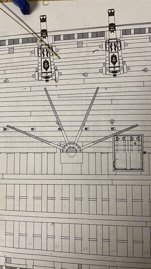
also the Le Fleuron had f.e. removable pillars when using the capstan (red arrows)


and I guess thy had also to remove the ladder (green arrow)

First of all - the bars were higher, than the guns, so no conflict directly.
but the outer seaman had problems, than he stpped pushing and moved inwards, after the the hinderance he moved back to the outer place at the bar and restarted pushing together with others (all during permanent moving the capstan
But in principle we have to have in mind, that the capstan was in work usually only during lifting of heavy loads.
f.e. in harbour - the guns near the capstan were secured parallel to the ship wall, so 90° turned and lashed alongside
or f.e. for lifting the anchors, boats or any yard arms - the same
means during the activity of using the capstans, 99,9% there was no action, where they used the guns.
f.e. on the fore jeer capstan of the HMS Victory (where I know about) - they had to remove completely all round pillars and ladders close to the capstan, otherwise it would not be possible to work - as I have in mind there were 120 seaman at one capstan in two floors in the same time working
I have a very good photo in my copies, made by my friend @dafi showing this activity on his beautiful model of the HMS Victory, where he discussed this detail once. Maybe it is possible for Daniel to explain more in detail
taken from:
Forum für historischen Schiffsmodellbau und Geschichte
Projektorientierte Quellensammlung und Datenbank für historischen Schiffsmodellbau und Geschichte
www.segelschiffsmodellbau.com
also the Le Fleuron had f.e. removable pillars when using the capstan (red arrows)
and I guess thy had also to remove the ladder (green arrow)
It is obvious that this would not be a thing of the moment necessity but planned and coordinated before hand. The explanation is very helpful in understanding more about seamanship in those times. RIch (PT-2)Interesting subject.
First of all - the bars were higher, than the guns, so no conflict directly.
but the outer seaman had problems, than he stpped pushing and moved inwards, after the the hinderance he moved back to the outer place at the bar and restarted pushing together with others (all during permanent moving the capstan
But in principle we have to have in mind, that the capstan was in work usually only during lifting of heavy loads.
f.e. in harbour - the guns near the capstan were secured parallel to the ship wall, so 90° turned and lashed alongside
or f.e. for lifting the anchors, boats or any yard arms - the same
means during the activity of using the capstans, 99,9% there was no action, where they used the guns.
f.e. on the fore jeer capstan of the HMS Victory (where I know about) - they had to remove completely all round pillars and ladders close to the capstan, otherwise it would not be possible to work - as I have in mind there were 120 seaman at one capstan in two floors in the same time working
View attachment 254419 View attachment 254420
I have a very good photo in my copies, made by my friend @dafi showing this activity on his beautiful model of the HMS Victory, where he discussed this detail once. Maybe it is possible for Daniel to explain more in detail
View attachment 254421
taken from:
Forum für historischen Schiffsmodellbau und Geschichte
Projektorientierte Quellensammlung und Datenbank für historischen Schiffsmodellbau und Geschichte
also the Le Fleuron had f.e. removable pillars when using the capstan (red arrows)
View attachment 254422 View attachment 254424
and I guess thy had also to remove the ladder (green arrow)
View attachment 254423
- Joined
- Mar 18, 2021
- Messages
- 350
- Points
- 323

The research I did for the Victory is imho only applicable for the english vessels. There the lenght of the bars was like this, that they had to take out a dozen pillars with the help of a jack and put the cannons alongside the hull.
The French worked differently. They had removable iron posts with hinges on the deck beams, so they simply swung them up and lashed them there. Blaise Oliver describes this nicely. For the length of the french bars I would trust the official drawings, even if they might be shorter than the english version.
But I think better ask someone who is more firm than me in the french builds of that period
XXXDAn

Photos from the reconstruction of the "Hermione" in Rochefort.


All the posts that are in the working area of the capstan are hinged at the top and can be folded upwards. On the ground, they are secured by two lateral holders or swing into cutouts. Fixed posts have a surrounding wooden border at the bottom.
Best regards
Thomas
All the posts that are in the working area of the capstan are hinged at the top and can be folded upwards. On the ground, they are secured by two lateral holders or swing into cutouts. Fixed posts have a surrounding wooden border at the bottom.
Best regards
Thomas
Last edited:


Upps - I know this good looking guy very well ")

It was really a great week in France - good friends and a lot of amazing models
It was really a great week in France - good friends and a lot of amazing models
Kurt Konrath
Kurt Konrath
These photos are first I have ever seen showing the stowed location of the Capstain bars! Good to see how some ships secured them. Not seen in many ships diagrams.And here some shots when I was there with @UwekDo you remember the fateful day and the small incident in the side gallery?
View attachment 254738
View attachment 254739
View attachment 254740
View attachment 254741
View attachment 254742
XXXXDAn
As I think about this, structural dead loads cannot be changed but "live loads" above the hinged posts would have to be removed as the overhead beams will deflect downwards during the rotations without the related posts in place and functioning as structurally designed. Just thinking structurally as a retired architect. Very informative series of photos. Thanks. Rich (PT-2)And here some shots when I was there with @Uwek
View attachment 254738
View attachment 254739
View attachment 254740
View attachment 254741
View attachment 254742
XXXXDAn
I understood that these stanchions/pillars were installed during one of Victory's restorations to add support for the deteriorating deck structure,Interesting subject.
First of all - the bars were higher, than the guns, so no conflict directly.
but the outer seaman had problems, than he stpped pushing and moved inwards, after the the hinderance he moved back to the outer place at the bar and restarted pushing together with others (all during permanent moving the capstan
But in principle we have to have in mind, that the capstan was in work usually only during lifting of heavy loads.
f.e. in harbour - the guns near the capstan were secured parallel to the ship wall, so 90° turned and lashed alongside
or f.e. for lifting the anchors, boats or any yard arms - the same
means during the activity of using the capstans, 99,9% there was no action, where they used the guns.
f.e. on the fore jeer capstan of the HMS Victory (where I know about) - they had to remove completely all round pillars and ladders close to the capstan, otherwise it would not be possible to work - as I have in mind there were 120 seaman at one capstan in two floors in the same time working
View attachment 254419 View attachment 254420
I have a very good photo in my copies, made by my friend @dafi showing this activity on his beautiful model of the HMS Victory, where he discussed this detail once. Maybe it is possible for Daniel to explain more in detail
View attachment 254421
taken from:
Forum für historischen Schiffsmodellbau und Geschichte
Projektorientierte Quellensammlung und Datenbank für historischen Schiffsmodellbau und Geschichte
also the Le Fleuron had f.e. removable pillars when using the capstan (red arrows)
View attachment 254422 View attachment 254424
and I guess thy had also to remove the ladder (green arrow)
View attachment 254423


It is evident that there is a lot of very detailed work in this ship as you bring up from the keel. Very precise work. Rich (PT-2)All deck beams for the upper cannon deck are loosely set and already have the notches for the planking. I am currently building the tiller with metal reinforcements.View attachment 259384View attachment 259385View attachment 259386
WOW - great progress
it is looking like a huge work there on the gun deck with all the guns tackled the prepared beams etc.
Very good work
it is looking like a huge work there on the gun deck with all the guns tackled the prepared beams etc.
Very good work
- Joined
- Oct 31, 2019
- Messages
- 230
- Points
- 298
I am now working my way deck beam by deck beam from stern to bow. Iron supports (made of brass) are again attached to each beam. Each beam is additionally attached to the fuselage with metal struts. I use brass foil that has been cut out. In addition, I now create missing equipment such as columns or partition walls with doors. And at the level of the cannon hatches, a pulley system is attached to open the hatches.


Last edited by a moderator:
You have put in a lot of hours making and installing the gunnery on this deck. Amazing small details with each cannon. Definiatly preplanned sequence . You will have a very fine finished model. Rich (PT-2)I am now working my way deck beam by deck beam from stern to bow. Iron supports (made of brass) are again attached to each beam. Each beam is additionally attached to the fuselage with metal struts. I use brass foil that has been cut out. In addition, I now create missing equipment such as columns or partition walls with doors. And at the level of the cannon hatches, a pulley system is attached to open the hatches.


