-

Win a Free Custom Engraved Brass Coin!!!
As a way to introduce our brass coins to the community, we will raffle off a free coin during the month of August. Follow link ABOVE for instructions for entering.
-

PRE-ORDER SHIPS IN SCALE TODAY!
The beloved Ships in Scale Magazine is back and charting a new course for 2026!
Discover new skills, new techniques, and new inspirations in every issue.
NOTE THAT OUR FIRST ISSUE WILL BE JAN/FEB 2026
You are using an out of date browser. It may not display this or other websites correctly.
You should upgrade or use an alternative browser.
You should upgrade or use an alternative browser.
H.M.S. Surprise by Artesania Latina - Build log
- Thread starter RegW
- Start date
- Watchers 29
-
- Tags
- artesania latina surprise
Top deck roughed-in and ready for sanding job.

Stern section needs lots of work.
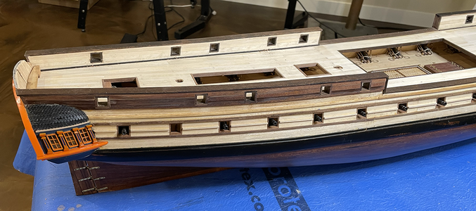
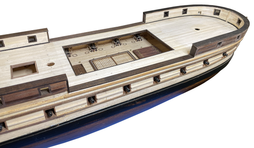
Happy with the bow. I feel an improvement with my plank bending skill, but I'd never take it up as an occupation. LOL!
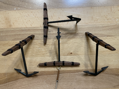
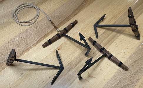
Assembled the anchors while waiting for glue to set. Had no idea that each anchor would have 30 parts to it. Ack!! So, one
hundred and twenty parts later...
 .
. 
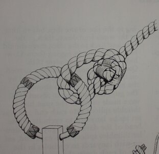
In my research I was unable to find a definitive answer to the exact anchor cable attachment configuration (and cable treatment),
for the 1750 AD period, so I just went with the A.L. plans. Shrug.

Stern section needs lots of work.

Happy with the bow. I feel an improvement with my plank bending skill, but I'd never take it up as an occupation. LOL!

Assembled the anchors while waiting for glue to set. Had no idea that each anchor would have 30 parts to it. Ack!! So, one
hundred and twenty parts later...
 .
. 
In my research I was unable to find a definitive answer to the exact anchor cable attachment configuration (and cable treatment),
for the 1750 AD period, so I just went with the A.L. plans. Shrug.
I didn't even know AL made a kit of the Surprise. She is looking very nice !
You mentioned in post 18 that the actual ship did not have train tackle eyebolts. I agree there would not have been two for such small cannon, but there would have been one in this time period. From Adrian Caruana, The History of English Sea Ordnance volume II page 386 (ISBN 0-948864-22-2) there was a ring for each cannon for the train tackle which was introduced in the 18th century and continued into the 19th century. Initially the ring on the deck was a ring bolt, then later an eyebolt. He also shows drawings of the running out and train tackle.From the instruction manual:
Allan
Last edited:
The problem I had with the A.L. diagram is that the cannon is positioned for active firing. If the cannon was actually fired with the train tackle as depicted, the tackle would take all of the recoil force, rather than the actual recoil arrestor cable. This would be dangerous to the gun crew and probably destroy the tackle itself in short order. My thoughts only.You mentioned in post 18 that the actual ship did not have train tackle eyebolts. I agree there would not have been two for such small cannon, but there would have been one in this time period. From Adrian Caruana, The History of English Sea Ordnance volume II page 386 (ISBN 0-948864-22-2) there was a ring for each cannon for the train tackle which was introduced in the 18th century and continued into the 19th century. Initially the ring on the deck was a ring bolt, then later an eyebolt. He also shows drawings of the running out and train tackle.
Allan
Hi Reg, You are right about the tackle not being in place when the cannon were being fired. The rigging shown in the kit instructions is inaccurate but your photo has a note that there were no ring bolts on the deck of the actual ship, thus my comment. The running out tackle which is shown in their picture laid loosely on the deck when the gun was run out for firing, not attached in any way to the training tackle ring bolts which were fixed in place even when not in use. The photo of how the kit folks rigged this cannon shows a lot of unrealistic things from brass trucks to blocks wired to the bulkhead but, the presence of a ring bolt or eyebolt for each cannon is correct.
Allan
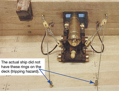
Allan

Last edited:
Your comments and notes regarding the ring bolts are appreciated and thanks. I'll include these on the top deck, but have the tackle set neatly as I did for the gun deck. I rigged the gun deck cannons with hooks on the arrestor cables and blackened the cannons, but got lazy and left the trucks brass. If I work up the courage to ever build a second ship, I'll correct this error. I appreciate your suggestions and please keep them coming.Hi Reg, You are right about the tackle not being in place when the cannon were being fired. The rigging shown in the kit instructions is inaccurate but your photo has a note that there were no ring bolts on the deck of the actual ship, thus my comment. The running out tackle which is shown in their picture laid loosely on the deck when the gun was run out for firing, not attached in any way to the training tackle ring bolts which were fixed in place even when not in use. The photo of how the kit folks rigged this cannon shows a lot of unrealistic things from brass trucks to blocks wired to the bulkhead but, the presence of a ring bolt or eyebolt for each cannon is correct.
Allan
View attachment 449485
If anyone knows an easy way to make sheaves in the pin rail stanchions please let me know. This is the first one I've attempted and it took me too long. Not overjoyed with the result either. I've got 4 more to go. The A.I. plan does not show these as a feature, but all of the illustrated books I've collected verified that the masts pin rails usually have these... and there are probably supposed to be 3 sheaves in each post - which is beyond my ability!
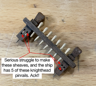
The piece is using walnut wood. I drilled pilot holes at 0.5mm diameter then enlarged them in steps to 1.0mm. Used my dental bits in a HSP tool to start the groves and finished the "internal pulleys" using an angled 0.7mm drill bit and dremel at slowest rotation speed. Finally finished with a fine jewellers file to smooth
the edges. The walnut is a 5x5mm stick at the beginning.
Last edited:
The first time that I ever saw this ship was in the late 1970s. She named HMS Rose and was docked in Newport, Rhode Island. She was later moved to Bridgeport, Connecticut. I later ran into her in San Diego, California, but she was renamed HMS Surprise but I do not know what had been changed to reflect the new name. If anyone can enlighten us, I would greatly appreciate it.I've been working on this kit for a few months now, but am remiss with photographing the progress. It's my first ship and I'm glad for the tools I've collected
for the RC aircraft I've built over the years.... but ships clearly require more clamps!!
View attachment 433065
View attachment 433066
I attached some 90º angled aluminum strips to the hull to ensure the keel remains straight and true - also makes a suitable stand for the initial work.
View attachment 433067
Upper planking nearly complete. Not unhappy with the results to far.
View attachment 433068View attachment 433069
Starting the lower planking here. The DC electrical system has been roughed-in. I picked up some
"pica" sized flickering (candle-like) LEDs to illuminate the gun deck as well as the lanterns above deck.
I've tested them, and they look very similar to miniature candles!
View attachment 433071View attachment 433072
View attachment 433073
Bill
Hello Bill, HMS Rose was renamed after the movie "Master and Commander" was filmed using the ship. As the movie became popular the tourist organization that owned her decided to rename her to HMS Surprise that was posted during the film. Wiki info noted that Rose was built using the original plans from ~1750 AD, but the top deck was modified for tourism and had fewer cannons than the A.L kit includes.The first time that I ever saw this ship was in the late 1970s. She named HMS Rose and was docked in Newport, Rhode Island. She was later moved to Bridgeport, Connecticut. I later ran into her in San Diego, California, but she was renamed HMS Surprise but I do not know what had been changed to reflect the new name. If anyone can enlighten us, I would greatly appreciate it.
Bill
Thanks for responding so quickly. Yes, I understand the history but, until now, had questioned the relation between the HMS Rose and the AL kit. I knew that the Mamoli kit of HMS Surprise was not accurate since it is based on a different class of French frigate than the real ship. I was simply wondering about the AL kit.
Bill
Bill
Hello northern neighbor! I'm in Minnesota. On parts this small, you are fighting against the coarseness of the wood grain. Cutting holes in small parts typically ends up with split pieces and lots of swearing. To increase your chances of success, first avoid woods that have a coarse grain like oak and mahogany and brittle woods like walnut in favor of finer grain woods like birch beech, maple or cherry.If anyone knows an easy way to make sheaves in the pin rail stanchions please let me know. This is the first one I've attempted and it took me too long. Not overjoyed with the result either. I've got 4 more to go. The A.I. plan does not show these as a feature, but all of the illustrated books I've collected verified that the masts pin rails usually have these... and there are probably supposed to be 3 sheaves in each post - which is beyond my ability!
View attachment 449648
Now, as for cutting the slots for the sheaves, your best bet is a micro mill bit in a small milling machine, taking light cuts until you're through the part. Precision is key on this scale. It will be tough to squeeze three slots in, but it can be done. Usually at small scale (i.e. 1:100), modelers just cut two holes with a shallow slot between them and don't use a sheave at all. at 1:48 scale, sheaves in knightheads are doable. If you have to have sheaves, you'll find brass in thin discs can work well, even if you have to use a punch on some sheet brass to make then and carefully needle file the edges concave by hand. All this takes lots of time, patience, and practice, but if that is the high level of detail you want to use, it is doable.
Last edited:
The A.L. kit has a number of rather significant omissions from the actual ship that currently berths in S.Diego. The kit does not include the raised aft section of the top deck, which gives the stern cabin a higher ceiling and changes the stern profile significantly. I made a feable attempt to correct this, but was largely unsuccessful. This is my first ship model, which is a poor excuse, but I am enjoying the build and learning curve.Thanks for responding so quickly. Yes, I understand the history but, until now, had questioned the relation between the HMS Rose and the AL kit. I knew that the Mamoli kit of HMS Surprise was not accurate since it is based on a different class of French frigate than the real ship. I was simply wondering about the AL kit.
Bill
It sounds like I would have to build a poop deck aft above the Captain's Quarters. Would I have to change the quarter and aft galleries?The A.L. kit has a number of rather significant omissions from the actual ship that currently berths in S.Diego. The kit does not include the raised aft section of the top deck, which gives the stern cabin a higher ceiling and changes the stern profile significantly. I made a feable attempt to correct this, but was largely unsuccessful. This is my first ship model, which is a poor excuse, but I am enjoying the build and learning curve.
Bill
Hi Bill, I think that the quarter and aft galleries would only require higher walls. The real challenge would be changing the frames to accommodate the raised top deck in the aft section, and making the stern bulkhead taller to fit the raised profile. The benefit is that the stern would look much better than the "compressed" stern bulkhead that my build has. I did make mine wider to permit scale windows and pillars. If you changed the frames, then the port and starboard windows would have the correct distance above the aft cabin floor. Mine are within 8 in (full scale size) of being floor to ceiling windows - which no ship would have.It sounds like I would have to build a poop deck aft above the Captain's Quarters. Would I have to change the quarter and aft galleries?
Bill
When there are three sheaves sometimes the design is changed having a side piece added to the bitt pins to accommodate the outboard sheave. Also, keep in mind the width of the slot and thickness of the sheave is dependent on the diameter of the rope that passes under the sheave so each may be different. For our scales, this will be barely noticeable. You can see the different sheave thicknesses and diameter in the drawing below from Peter Goodwin's The Construction and Fitting of the British Man of War, page 220.
Allan
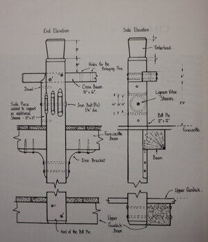
Allan

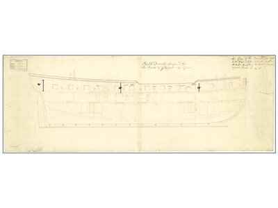
Sorry to ask, but are you referring to the upper deck or quarter deck? Looking at the contemporary drawings of Rose (aka Surprise) there is no raised portion of the either of these decks, thus my confusion. There is a 2" rise of the QD from 68 inches to 70 inches from the bottom of the QD deck beams to the top of the upper deck planking. https://www.rmg.co.uk/collections/objects/search/Rose 1757 Is this what you are referring to? I believe the modern ship for the movie was a 28 gun, but the dimensions would be similar between decks. There is a great high resolution inboard profile drawing of the 28 gun ships of the Active class that is easier to see. It can be found on page 4 in the Wiki Commons site. It is too large to post here. https://commons.wikimedia.org/w/ind...dalupe_(1763),_Carysfort_(1766)_RMG_J6385.pngThe kit does not include the raised aft section of the top deck, which gives the stern cabin a higher ceiling and changes the stern profile significantly.
Thanks Reg.
Allan
Last edited:
It seems that there are questions about the Rose to Surprise transition. I hadn't considered that the ship appeared in the movie as a 28-gunner. The real Surprise was a 24-gunner. That alone might affect the length. But, I like a motto I read here; Build what you like and like what you build.
Bill
Bill


