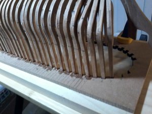
Thanks Zoly, Can not believe I was so stupid not to relize what I was doing have built the Caustic from Dave and had the same type of jig, so know reason not to have know, just another senior citizen moment. DON
-

Win a Free Custom Engraved Brass Coin!!!
As a way to introduce our brass coins to the community, we will raffle off a free coin during the month of August. Follow link ABOVE for instructions for entering.
-

PRE-ORDER SHIPS IN SCALE TODAY!
The beloved Ships in Scale Magazine is back and charting a new course for 2026!
Discover new skills, new techniques, and new inspirations in every issue.
NOTE THAT OUR FIRST ISSUE WILL BE JAN/FEB 2026
You are using an out of date browser. It may not display this or other websites correctly.
You should upgrade or use an alternative browser.
You should upgrade or use an alternative browser.
Halifax Build Log: Lumberyard
- Thread starter donfarr
- Start date
- Watchers 14
-
- Tags
- halifax lumberyard
This weekend i want to try something as i think i have a cool unique way to lock the framea in place without all those clamps in the way
You know those turnbuckles you see ie the smaller ones, well my idea cut the hooks off grind a point on each side then put them inside jjugjig and just tighten them up. The point will snug into the frame and if you pic tig up it shou"d keep frame in jig and the little turnbuckle be inside of jig out of the way
Moving along well Don. Dave advised that the kit for NBM is almost ready to ship. Getting itchy fingers and can't wait to get started. Its been a while since I was able to sit down and build a model so I'm really looking forward to it.
Joseph, I like the idea of the turnbuckles. I've used them in a similar application.
Joseph, I like the idea of the turnbuckles. I've used them in a similar application.
Progress pictures of FRAMES A THRU J FASTNED IN PLACE, I opted for this method of installing frames using bot Dave and Hahns method, I was worried if I turnded jig over as Dave sugested it would be to unstable to work on so I left it like a Hahn style upside down jig, BUT I USED DAVE SUGESTION OF RAISING THE FRAMES TO MEET THE KEEL NOTCHES, as it would not matter as they will be cut off latter, I first installed FIRST AND LAST WHOLE FRAME(FRAME No A AND V) then glued the keel assembly to them, also note the FRAMES WERE CLAMPED TIGHT AGAINST TH BACK OF JIG after sanding frames to center on the keel, I will have another 3 frames in place by tonight....SO I AM GOING TO NEED HELP FROM DAVE ON THE CANT FRAMES BEVELS AND THE PLACING OF THE HALF FRAMES.
Frames A thru J installed. Showing frames glued to keel assembly. Showing frames raised up so that they fit into keel notches and then glued in place. Frames A thru J installed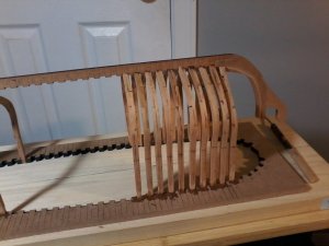
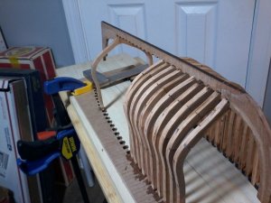
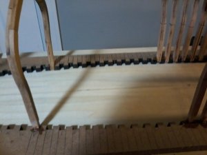
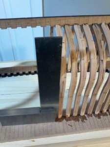
Frames A thru J installed. Showing frames glued to keel assembly. Showing frames raised up so that they fit into keel notches and then glued in place. Frames A thru J installed


I was noticing what looks like gaps between the futtock joints is it just the angle or are there gaps and for a reason?
Yes there are some gaps in the joints will fill them withe a mixture of sanding dust, white glue and water, when cut from jig, should have been done before installing other frames were done. Don
ok thanks i just wasnt sure if there was any certain reason me being new and all to ship stuff
THANKS MIKE, DAVE NEED HELP WITH CANT FRAMES BEVELS, AND HALF FRAMES.....ALSO HOW TO DETERMINE THE UNDERSIDE OF RAIL FOR THE CANT AND HALF FRAMES. Don
Hi Everyone, Have not posted in a while, pictures to follow on the progress sometime this week; ...update all whole frames are installed, dry fitting stern Half Frames, and Stem Cant frames,...some mistakes were made will not in this build gloss over them, will show them and solutions that I have come up with to fix them hopefully, and any sugestions for improvement will be greatly appreciated. THANKS Don
- Joined
- Dec 1, 2016
- Messages
- 6,372
- Points
- 728

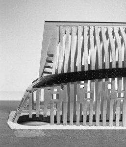
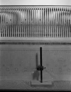
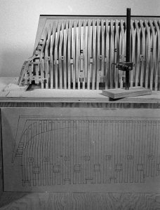
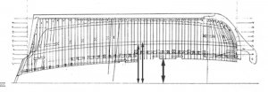
you can see the pencil lines where Harold drew in where the wales will go. The way he did this is to take measurements off the plans and transfer them to the model for the Halifax you measure up from the jig to whatever you want to locate either the wales or under the caprail. Take a measurement from the jig to the bottom of the keel to make sure you have the correct distance from the jig to the bottom of the keel.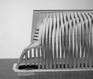


- Joined
- Dec 1, 2016
- Messages
- 6,372
- Points
- 728

JosephH said:I was noticing what looks like gaps between the futtock joints is it just the angle or are there gaps and for a reason?
Those gaps you see are from the way the laser is cutting depending on the focus of the beam the cut on the back side is greater than the front side causing the cut to be on a slight angle.
there are 2 things you can do as don said just fill the gap. What I do is ever so slightly touch the end of the piece to the center of my 4 inch disk sander and that squares the ends off and removes the char. If you don't have a disk sander I have also used a square block with sand paper on one surface and just a pass or two squares up the end
when you place the parts together there is a gap on one side
Happy you are back Dave, a couple of questions for you, you SAID THAT FOR WHATEVER LEGAL REASONS THAT THE PLANS WERE DISTORTED, can I still take the mesurments off the plans, when I first put together theKEEL ASSEMBLY IT WAS QUITE A BIT OFF FROM THE PLANS, what do I do,....also I elected to put the KEEL ASSEMBLY IN PLACE WIT FRAMES No. A AND V(first and last whole frame) and CLAMPED THE FRAMES TO THE KEEL NOTCHES,.....then adjusted the frames to the jig, mostly pulled up from the bottom of the jig, this would not matter as the frames eventually get cut off from the jig itself,....but would it not change the mesurments to underside of CAP RAIL AND THE WALE ITSELF,,,,,,pictures forth comming, NEED YOUR HELP ON THIS AND THE CANT FRAME BEVELING,...I JUST CAN NOT SEEM TO GET THAT THROUGH MY ANCIENT MIND, looking forward to your help. Don
OK starting to post pictures. Showing a mistake and how I corected it,this is Frame No. 9, showing it wrong, taking it apart by using nail polish remover with 100 per cent acetone, using cotton swab on the joints and an ezato blade got it apart with no damage re-did the frame correctly, this is what happens when you are to tired to do modeling work.![20170817_220045[1525].jpg 20170817_220045[1525].jpg](https://shipsofscale.com/sosforums/data/attachments/7/7409-4ef370ca1ee03a451679bcd3d3814039.jpg?hash=TvNwyh7gOk)
![20170817_220045[1525].jpg 20170817_220045[1525].jpg](https://shipsofscale.com/sosforums/data/attachments/7/7409-4ef370ca1ee03a451679bcd3d3814039.jpg?hash=TvNwyh7gOk)
so now I know it is working again, here are the posts showing progress and questions. Cant frames No. 5, 6, and 7 dry fitted, is this correct once I get it into rabbit, do I need any beveling yet. Stern off center, will fix it when installing the half frames by pushing them in. Side view wit half frame No. W dry fitted. Whole frames attached to keel
whole frames installed to keel and jig.![20170823_201854[1547].jpg 20170823_201854[1547].jpg](https://shipsofscale.com/sosforums/data/attachments/7/7429-467ad14976b9ee9022c586e8f1a24314.jpg?hash=RnrRSXa57p)
![20170823_200247[1551].jpg 20170823_200247[1551].jpg](https://shipsofscale.com/sosforums/data/attachments/7/7431-f1f354be283627e188d22d075fbd355c.jpg?hash=8fNUvig2J-)
![20170823_195055[1552].jpg 20170823_195055[1552].jpg](https://shipsofscale.com/sosforums/data/attachments/7/7432-1332754f07e9e10fd18ac9ee7f113893.jpg?hash=EzJ1Twfp4Q)
![20170823_195339[1557].jpg 20170823_195339[1557].jpg](https://shipsofscale.com/sosforums/data/attachments/7/7433-5ce24e641a45c877b5aeeced3c944ae3.jpg?hash=XOJOZBpFyH)
![20170823_195443[1556].jpg 20170823_195443[1556].jpg](https://shipsofscale.com/sosforums/data/attachments/7/7434-e40566aa944b13ad4c99eabe0ab261ff.jpg?hash=5AVmqpRLE6)
whole frames installed to keel and jig.
![20170823_201854[1547].jpg 20170823_201854[1547].jpg](https://shipsofscale.com/sosforums/data/attachments/7/7429-467ad14976b9ee9022c586e8f1a24314.jpg?hash=RnrRSXa57p)
![20170823_200247[1551].jpg 20170823_200247[1551].jpg](https://shipsofscale.com/sosforums/data/attachments/7/7431-f1f354be283627e188d22d075fbd355c.jpg?hash=8fNUvig2J-)
![20170823_195055[1552].jpg 20170823_195055[1552].jpg](https://shipsofscale.com/sosforums/data/attachments/7/7432-1332754f07e9e10fd18ac9ee7f113893.jpg?hash=EzJ1Twfp4Q)
![20170823_195339[1557].jpg 20170823_195339[1557].jpg](https://shipsofscale.com/sosforums/data/attachments/7/7433-5ce24e641a45c877b5aeeced3c944ae3.jpg?hash=XOJOZBpFyH)
![20170823_195443[1556].jpg 20170823_195443[1556].jpg](https://shipsofscale.com/sosforums/data/attachments/7/7434-e40566aa944b13ad4c99eabe0ab261ff.jpg?hash=5AVmqpRLE6)
Where are the pictures for these items how do I get them up. DON
I AM REFERING TO didits posts(FOR 8/22) need to know how to open the pictures on these items. DON
A
Aussie048
Guest
Hi Don
We need Didit to fix those as we do not have the photos. If you or Didit has the photos or you emailed me with them I could fix the posts.
Cheers
Geoff
We need Didit to fix those as we do not have the photos. If you or Didit has the photos or you emailed me with them I could fix the posts.
Cheers
Geoff


