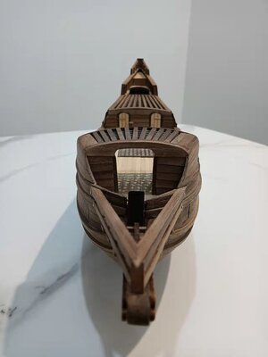
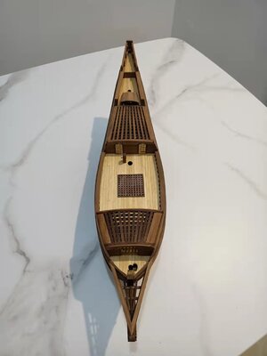
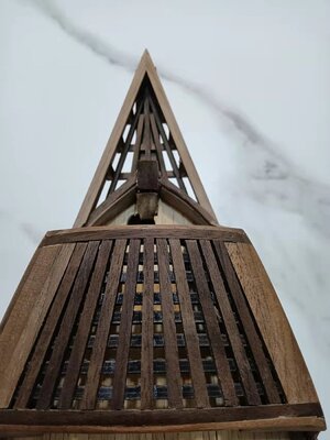
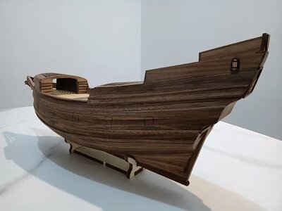
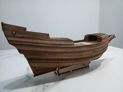
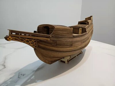
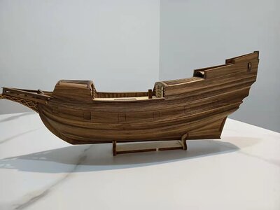
HIGH HOPES, WILD MEN AND THE DEVIL’S JAW - Willem Barentsz Kolderstok 1:50

Hello Dear Friends

Among all the cuisine, the Lincoln Park Shipyard was a hive of activity today. With all classes cancelled, I had a whole day to spend in the shipyard - building, and while the glue was drying, researching.

Today I wanted to continue with the galleon part of the Willem Barentsz. It is better to illustrate the sequence of events on the plans than by means of photographs.

View attachment 302705

First three crossbeams (marked in red) were glued onto the beakhead base at intervals as specified by the plans. These consisted of 2mm x 3mm walnut strips.

View attachment 302706

On top of the newly-laid crossbeams, are then glued four of the same 2mm x 3mm walnut strips so that their feet rest on the crossbeams, while their outer edges are glued to the inner edge of the two side railings that were already placed last night. The two uprights closest to the stem do not require a crossbeam, as the taper of the beakhead allows them to be glued directly on the base of the beakhead.

View attachment 302707

When that is done the floor is then laid consisting of four 2mm x 2mm walnut strips which are glued lengthwise into the positions as shown on the plans.

And what then was all done, this was what I had ended up with:

View attachment 302709

All the protrusions will be sawed / filed / sanded nice and flush tomorrow, but I always allow the glue a full 24-hours to dry before I do that. What I found most interesting, was that I could cut the floor beams on the plan and then they would then slot perfectly into their predetermined positions. This indicates that I have built this portion of the ship exactly as per the plans. That will be a first and a last for me! ROTF

View attachment 302710

View attachment 302711

I am really very happy with what I could accomplish today as far as the build goes. However, looking at these macro close-ups, there is still an awful lot of overall cleaning up and finishing-off in general that needs to be done.

As a matter of interest and just for comparison, I have placed the little boat on the Kolderstok plans - no problem with fitting into its rightful place!

View attachment 302714

For the research part of today, stay tuned ...
Lovely Heinrich- I’m still waiting for my firstROTF;). The Kolderstock plans/diagrams look brilliant. Cheers Grant
 
Hello Dear Friends

Among all the cuisine, the Lincoln Park Shipyard was a hive of activity today. With all classes cancelled, I had a whole day to spend in the shipyard - building, and while the glue was drying, researching.

Today I wanted to continue with the galleon part of the Willem Barentsz. It is better to illustrate the sequence of events on the plans than by means of photographs.

View attachment 302705

First three crossbeams (marked in red) were glued onto the beakhead base at intervals as specified by the plans. These consisted of 2mm x 3mm walnut strips.

View attachment 302706

On top of the newly-laid crossbeams, are then glued four of the same 2mm x 3mm walnut strips so that their feet rest on the crossbeams, while their outer edges are glued to the inner edge of the two side railings that were already placed last night. The two uprights closest to the stem do not require a crossbeam, as the taper of the beakhead allows them to be glued directly on the base of the beakhead.

View attachment 302707

When that is done the floor is then laid consisting of four 2mm x 2mm walnut strips which are glued lengthwise into the positions as shown on the plans.

And what then was all done, this was what I had ended up with:

View attachment 302709

All the protrusions will be sawed / filed / sanded nice and flush tomorrow, but I always allow the glue a full 24-hours to dry before I do that. What I found most interesting, was that I could cut the floor beams on the plan and then they would then slot perfectly into their predetermined positions. This indicates that I have built this portion of the ship exactly as per the plans. That will be a first and a last for me! ROTF

View attachment 302710

View attachment 302711

I am really very happy with what I could accomplish today as far as the build goes. However, looking at these macro close-ups, there is still an awful lot of overall cleaning up and finishing-off in general that needs to be done.

As a matter of interest and just for comparison, I have placed the little boat on the Kolderstok plans - no problem with fitting into its rightful place!

View attachment 302714

For the research part of today, stay tuned ...
Heinrich, when looking at the top views of both drawing and the actual model, it appears to me that the tip of the galleon is out of proportion in terms of thickness.
Is that due to distortion of the camera, or is that indeed the case?
 
Very nice Heinrich, Each addition to your ship continues to enhance its overall beauty.
Thank you so much Daniel. I still need to make today's work look neat and clean, but the foundation has been laid. :)
 
Heinrich, when looking at the top views of both drawing and the actual model, it appears to me that the tip of the galleon is out of proportion in terms of thickness.
Is that due to distortion of the camera, or is that indeed the case?
You have very sharp eyes Johan ROTF, but all is good. From the laser sheet the galleon is 8mm thick and then has to be tapered down to 4mm at the tip. This I have done, but then it gets the side ornamentation glued onto both sides, which results in a 6mm width, which the plans don't reflect.
 
I think the galleon looks very nice Heinrich. A beautifully designed detail that only adds to the rest of the lines of this ship. Bravo!
Thank you very much Paul. I can't wait to tidy that part up and place the top railing into position. That will give the whole nose more of a spear-point configuration, rather than the slightly blunt tip now. What I find amazing is how strong the galleon is - much much stronger in construction than the Haarlem - and a lot simpler to build!
 
Very nice work on the galleon. I'm not surprised that everything fit as well as it did.
Thank you verry much Jan. I did not really have an idea how to cut the angles on the floor planks, so I thought let me do it as per the plans and then do the necessary adjustments from there. But ... lo and behold ... they fitted without any modifications or adjustments necessary.
 
You have very sharp eyes Johan ROTF, but all is good. From the laser sheet the galleon is 8mm thick and then has to be tapered down to 4mm at the tip. This I have done, but then it gets the side ornamentation glued onto both sides, which results in a 6mm width, which the plans don't reflect.
Thanks for educating me on this detail. It was just that with the beautiful lines of the rest of this lovely ship, the galleon didn't make much sense to me. Other than that, nice work!
 
Hello Dear Friends

Last night I mentioned that I want to share something interesting with you - well, in actual fact there are two pieces of interesting news I have found. So let's start with the non-controversial one! :)

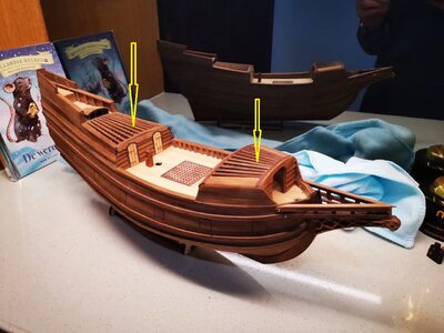
Maybe you have wondered, why the Willem Barentsz does not feature permanent decking on the structures midships and at the bow, but instead a net-like cover of lengthwise and crosswise wooden beams (see below as indicated by the yellow arrows).
微信图片_20220413184228.jpg

In my continuing research, I came upon this very interesting piece of information. As you know, I recently completed the Willem Barentsz’s front canopy (“overkapping” in Dutch). Reading about the overkapping and its history revealed that it was originally called a “vinkennet” (finch netting).

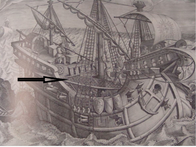
Now firstly we have to look at terminology. Both names for these structures contain the word "opbouw" - meaning a built-up structure. The one midships was simply called as "opbouw" and the one at the stem a "vooropbouw" or "overkapping". "Vooropbouw" simply means a raised structure at the front of the ship. Now originally, these structures were called a "vinkennet" or finch net.
schip1599.png

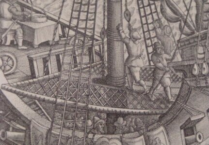
This image clearly shows the finch net. Originally, it was net of sturdy rope or chains that stretched between the forecastle and the deck behind it. - Source: Jan Zwart (Modelbouwforum)
vinkennet.JPG

Source: Jan Zwart - Modelbouwforum

The term finch-net gradually evolved into “boevennet” (crooks’ net), before it was corrupted into “bovenet” / bovennet” meaning (top net). This part is important as all terminology to the Willem Barentsz relates to boevenet (top net) as used by Ab Hoving.

Het Schip van Willem Barents - Ab Hoving

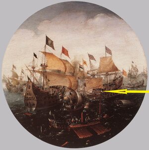
In his book, De vlootbouw in Nederland 1596-1655 weergeeft, (Shipbuilding in the Netherlands 1596-1655), Elias writes that at the beginning of the Eighty-Year War numerous Vlieboten and jachten were utilized by the Netherlands. In order to offer these vessels better protection against the much higher, built-up Spanish ships, they were equipped with a lattice- and chain framework that stretched between the forecastle and the deck behind it. The logic behind this was to offer protection to the crew during boarding raids from the enemy. During those days, victory at sea relied heavily on a successful boarding of the enemy; it was only much later that long-range cannon-fire became the decisive factor.

In the painting below by Aert Antonisz of “De Slag by Sluis” (The Battle at Sluis) a ship with boevenet is depicted.
seabattl.jpg

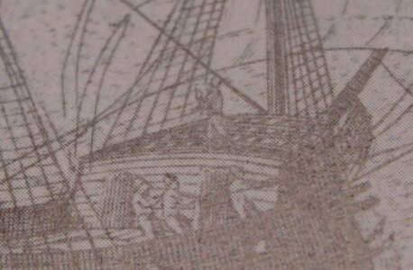
The following drawing though, offers a much better visual example (if somewhat grained).
1605.JPG

Nicolaes Witsen discusses the boevenet extensively, devoting a whole chapter to it, the drawing of the rafters and an explanation how it was built. Interestingly, he mentioned that the boevenet could be removed, resulting in an open canopy. This, however does raise the question why the vooropbouw then has front and rear “walls”.

So why is this important? If we examine the early jachten (of which the WB was one), and take into account that De Veer spoke of boevenetten it becomes clear that the WB was equipped with two in actual fact – one in the form of a half-deck midships and one in the form of the vooronder at the stem. These structures were not permanently closed with decking, but featured the wooden “netting” as seen on the WB as permanent replacements for the earlier finch nets..

And that is how we know why the Willem Barentsz looks the way she does! :D

Hopefully, I will be back a little later with a galleon update!
 
That is a very interesting piece of history. It’s incredible how names for items change to a final form as the years pass.
It does Jan - and that is what makes the research so difficult as the different names may refer to one and the same thing. The whole lifeboat issue of the WB is essentially a terminology one.
 
Back
Top