2. Trials and Experiments.
And again, this is my least favorite part of the build, but I've never given it up.
Making samples and experimenting with them seems like an interesting activity, but it often takes a lot of time, and sometimes it takes weeks or even months to see the results... for example, after applying oil and waiting before applying bitumen, or other moments of waiting for the results.
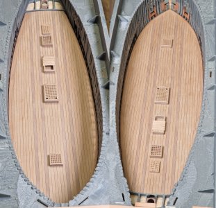
So, I've already shown that I created two large samples of the board and deck.

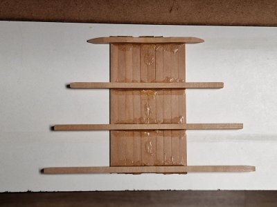
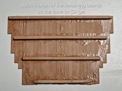
1. Before gluing, while preparing the material (the planks for the sheathing), I coated the boards with a thin layer of tung oil diluted 2:1 with thinner for oil-based paints. After selecting the right planks, I glued them in the correct order and position... and
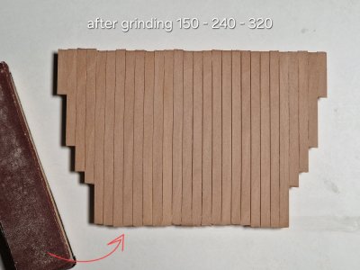
2. ... after gluing the planks, I sanded the surface with 320-grit sandpaper.
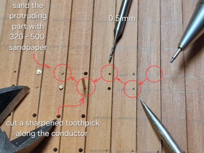
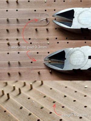
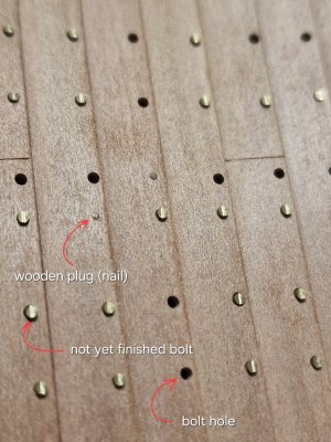
As I already showed, I secured and finished the dowels like this:
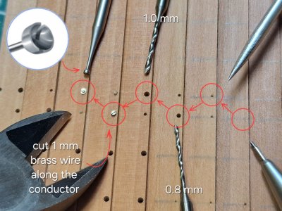
And I'll make the bolts like this:
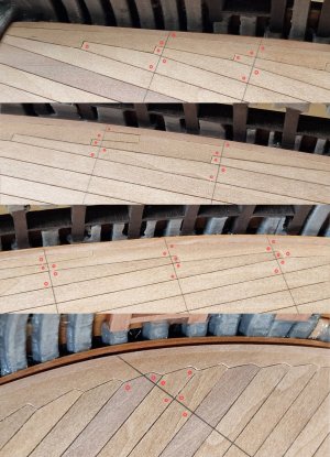
And I had a dilemma... I will do the bolts before applying oil and bitumen, and I will blacken them after... And I had a question, how will the blackening agent work after oil and bitumen... and here is the answer:

... simple! The blackening agent worked perfectly with the oil (Danish). But there's a point to consider!!! (By the way, I applied it with a special brush used in dentistry for applying bonding agents and adhesives).
The bolt at the bottom center had a long exposure time, and during that time, not only did it darken significantly (losing its features, turning into a solid blob), but the wood also became slightly pigmented, which is unacceptable.
But! If you apply the blackening agent for 2-4 seconds and immediately blot it with a napkin, not only will the wood be undamaged, but the metal will also be partially blackened, and the bolt's features will still be legible. (You'll need to experiment with the timing to achieve the perfect color. I'll show all this in more detail later.)
And the deck isn't difficult either:

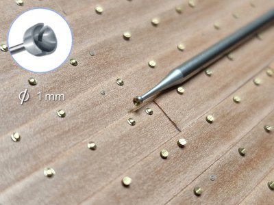
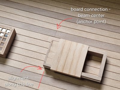
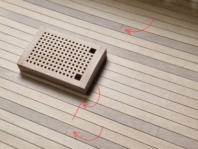
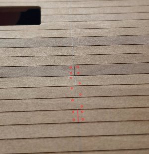
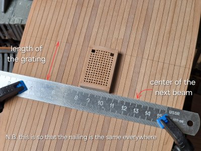
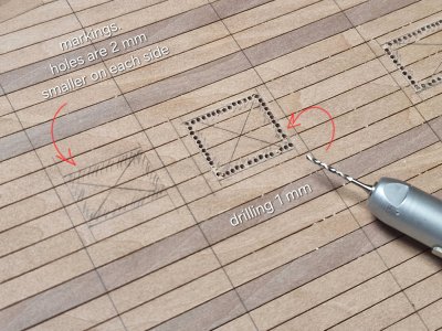
To make precise markings without using a pencil (which can leave streaks), you can cut 2mm-wide strips of masking tape (in my case) and place drilling holes on both sides. The key is to center the strip along the joints of the boards so the nails are equally spaced on both sides.
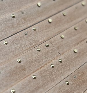
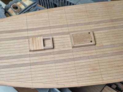
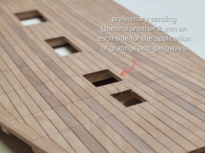
Then comes the drilling, the toothpicks, and the sanding. And finally, the result after oiling – the top two boards. I'm more than satisfied with the result. This sample will be coated with Danish oil (one and two coats for comparison), and next month it will be coated with bitumen... and I'm already looking forward to it...
UPD: I think I'll give up on Danish oil. Its advantage is that it dries quickly and has a pleasant scent, but unfortunately, it doesn't provide the same color change as Tung oil. I previously used Belinka but ordered Rustins Tung oil. So, I'll experiment for now.
With the side panel sample, after installing the bolts and applying the oil, I'll also be trying different concentrations of bitumen and blackening the bolts in a month... ah... it's so exciting, but it's better to test everything on samples a hundred times before doing everything on the model, you know...
And again, this is my least favorite part of the build, but I've never given it up.
Making samples and experimenting with them seems like an interesting activity, but it often takes a lot of time, and sometimes it takes weeks or even months to see the results... for example, after applying oil and waiting before applying bitumen, or other moments of waiting for the results.
So, I've already shown that I created two large samples of the board and deck.

1. Before gluing, while preparing the material (the planks for the sheathing), I coated the boards with a thin layer of tung oil diluted 2:1 with thinner for oil-based paints. After selecting the right planks, I glued them in the correct order and position... and
2. ... after gluing the planks, I sanded the surface with 320-grit sandpaper.
As I already showed, I secured and finished the dowels like this:

And I'll make the bolts like this:

And I had a dilemma... I will do the bolts before applying oil and bitumen, and I will blacken them after... And I had a question, how will the blackening agent work after oil and bitumen... and here is the answer:

... simple! The blackening agent worked perfectly with the oil (Danish). But there's a point to consider!!! (By the way, I applied it with a special brush used in dentistry for applying bonding agents and adhesives).
The bolt at the bottom center had a long exposure time, and during that time, not only did it darken significantly (losing its features, turning into a solid blob), but the wood also became slightly pigmented, which is unacceptable.
But! If you apply the blackening agent for 2-4 seconds and immediately blot it with a napkin, not only will the wood be undamaged, but the metal will also be partially blackened, and the bolt's features will still be legible. (You'll need to experiment with the timing to achieve the perfect color. I'll show all this in more detail later.)
And the deck isn't difficult either:

To make precise markings without using a pencil (which can leave streaks), you can cut 2mm-wide strips of masking tape (in my case) and place drilling holes on both sides. The key is to center the strip along the joints of the boards so the nails are equally spaced on both sides.
Then comes the drilling, the toothpicks, and the sanding. And finally, the result after oiling – the top two boards. I'm more than satisfied with the result. This sample will be coated with Danish oil (one and two coats for comparison), and next month it will be coated with bitumen... and I'm already looking forward to it...
UPD: I think I'll give up on Danish oil. Its advantage is that it dries quickly and has a pleasant scent, but unfortunately, it doesn't provide the same color change as Tung oil. I previously used Belinka but ordered Rustins Tung oil. So, I'll experiment for now.
With the side panel sample, after installing the bolts and applying the oil, I'll also be trying different concentrations of bitumen and blackening the bolts in a month... ah... it's so exciting, but it's better to test everything on samples a hundred times before doing everything on the model, you know...
Last edited:


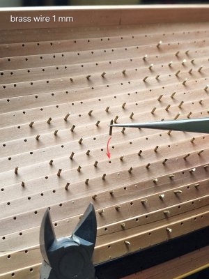
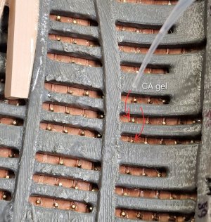
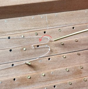
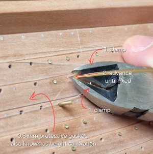
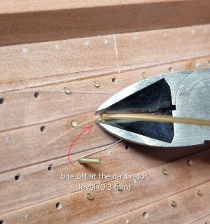
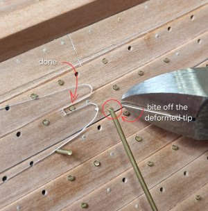
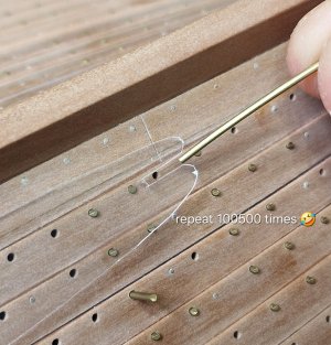


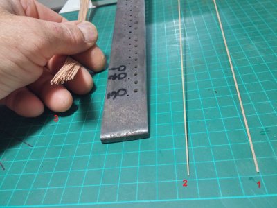
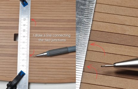
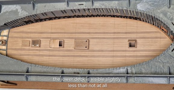
 , maybe I exaggerated the 1 second, but it can definitely be done in 2-3. But I still recommend the second option more.