Imitation bolts and nails.
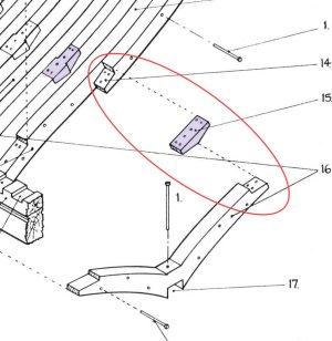
We continue to consult the anatomy and do as much as possible as in a book. Bolts fasten different parts of the case and you need to transfer their positions correctly. If you are guided by the image from below, the process is not difficult.
View attachment 523412
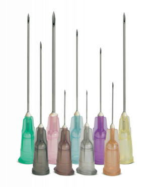
First of all, you need to make an imitation of bolts on the keelson and false keel. To do this, I used a slightly larger pen than for boards. Here are both for comparison. And visually it is clear that the cylindrical puncture is of different diameters.
View attachment 523413
Checked what it would look like and...
View attachment 523414
View attachment 523415
... made simulated bolts on the keelon, false keels and on the mast stop.
View attachment 523416
*By the way, the top photo shows the difference between a large and a small cylinder.
It was all done with a pink pen, where the diameter is larger). And now, on all boards you need to make an imitation with a blue handle (where the cylinder diameter is smaller).
View attachment 523417
View attachment 523418
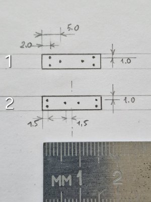
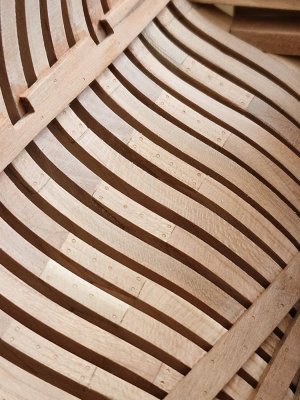
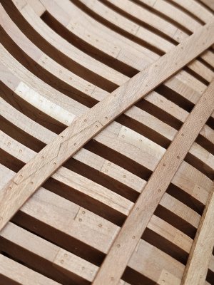
As you were able to notice, the nails beat one nail for each frame in a checkerboard pattern (either higher or lower). I redrawn the image a little from the anatomy and from this I already did all the imitation of nails inside the case.
View attachment 523419
To make it easier to visualize, I marked each board from the set with color in the image in anatomy.
View attachment 523420
And I also visualized the places where the boards are connected. It is clear from the numbers that the 1st board is the bottom and the higher the number, this board is higher.
The 4th board, which holds the upper deck beams, has the simplest locks. Firstly, they were already so in the set (you can't redo it). And secondly, this belt was reinforced from the outside with Main wale (by the way, it is depicted in the diagram above (outside). And plus - this belt was very strongly strengthened by the knees, both horizontal and vertical. Therefore, there was more than enough rigidity here. And most importantly, this belt will be practically invisible due to the knees.
View attachment 523421
View attachment 523422
On the 1st belt, (at the lowest) - there was also not a difficult connection, but longer (this is in anatomy).
View attachment 523423
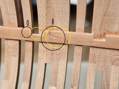
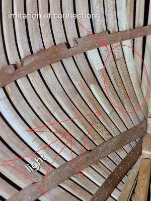
On the 2nd belt (not visible on anatomy), but logically there should have been a complex lock. Since this and the 3rd belt are very powerful and had to carry a heavy load. For this, complex castles were placed in such places.
View attachment 523424
On the third belt, similarly the same lock, for the same reasons.
View attachment 523425
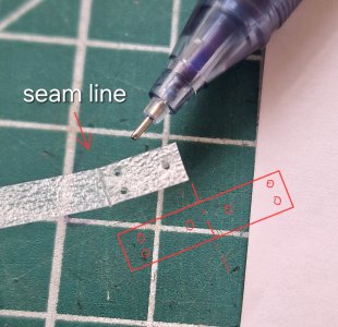
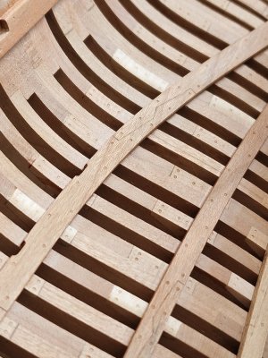
This is as you understand - an imitation of a connection (lock). It is done simply - the geometry of the lock is drawn, then a groove is pressed through with a straight scalpel. I do not recommend cutting (namely, pushing). Because when cutting - you can accidentally cut further than planned and also crooked.
View attachment 523426
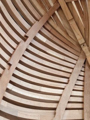
As for the connections, they all need to be placed in different places. This is necessary so that the case is equally strong everywhere and does not break at the joints in one column.
View attachment 523427
So the imitation nails on the inside boards are complete...
View attachment 523428
View attachment 523429
... and it took not so little time and effort (I'm already silent about the time that I could spend on real nagel and bolts...)
And my doubts crept in, but is it necessary to do imitation of bolts on the joints of the frames... according to a modest estimate, there should be more than 3,000 punctures with a pen... I will gather my thoughts and strength and I must decide... otherwise, you won't stop at half the road!
*Now everything is practically invisible, especially from a distance, but... this is before the oil coating. After the oil, everything will be clearly visible and imitation of bolts and nails and locks (already checked on the probes).




 Now, I figure, if no one will see it unless they disassemble the model, I don't think it's worth the effort (or the time).


 .
.
