• LUCZORAMA SHIPWRECK SCAVENGER HUNT GIVEAWAY. 4 Weeks of Fun • 1 Legendary Prize ((OcCre’s Fram Ship)) • Global Crew Welcome!
    **VIEW THREAD HERE**

HMS Alert [1777] 1:48 POF by serikoff. (Two hulls: skeleton and fully rigged)

Imitation bolts and nails.

We continue to consult the anatomy and do as much as possible as in a book. Bolts fasten different parts of the case and you need to transfer their positions correctly. If you are guided by the image from below, the process is not difficult.

View attachment 523412

First of all, you need to make an imitation of bolts on the keelson and false keel. To do this, I used a slightly larger pen than for boards. Here are both for comparison. And visually it is clear that the cylindrical puncture is of different diameters.

View attachment 523413

Checked what it would look like and...

View attachment 523414

View attachment 523415

... made simulated bolts on the keelon, false keels and on the mast stop.

View attachment 523416

*By the way, the top photo shows the difference between a large and a small cylinder.
It was all done with a pink pen, where the diameter is larger). And now, on all boards you need to make an imitation with a blue handle (where the cylinder diameter is smaller).

View attachment 523417

View attachment 523418

As you were able to notice, the nails beat one nail for each frame in a checkerboard pattern (either higher or lower). I redrawn the image a little from the anatomy and from this I already did all the imitation of nails inside the case.

View attachment 523419

To make it easier to visualize, I marked each board from the set with color in the image in anatomy.

View attachment 523420

And I also visualized the places where the boards are connected. It is clear from the numbers that the 1st board is the bottom and the higher the number, this board is higher.

The 4th board, which holds the upper deck beams, has the simplest locks. Firstly, they were already so in the set (you can't redo it). And secondly, this belt was reinforced from the outside with Main wale (by the way, it is depicted in the diagram above (outside). And plus - this belt was very strongly strengthened by the knees, both horizontal and vertical. Therefore, there was more than enough rigidity here. And most importantly, this belt will be practically invisible due to the knees.

View attachment 523421

View attachment 523422

On the 1st belt, (at the lowest) - there was also not a difficult connection, but longer (this is in anatomy).

View attachment 523423

On the 2nd belt (not visible on anatomy), but logically there should have been a complex lock. Since this and the 3rd belt are very powerful and had to carry a heavy load. For this, complex castles were placed in such places.

View attachment 523424

On the third belt, similarly the same lock, for the same reasons.

View attachment 523425

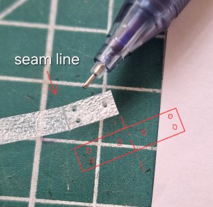
This is as you understand - an imitation of a connection (lock). It is done simply - the geometry of the lock is drawn, then a groove is pressed through with a straight scalpel. I do not recommend cutting (namely, pushing). Because when cutting - you can accidentally cut further than planned and also crooked.

View attachment 523426

As for the connections, they all need to be placed in different places. This is necessary so that the case is equally strong everywhere and does not break at the joints in one column.

View attachment 523427

So the imitation nails on the inside boards are complete...

View attachment 523428

View attachment 523429

... and it took not so little time and effort (I'm already silent about the time that I could spend on real nagel and bolts...)

And my doubts crept in, but is it necessary to do imitation of bolts on the joints of the frames... according to a modest estimate, there should be more than 3,000 punctures with a pen... I will gather my thoughts and strength and I must decide... otherwise, you won't stop at half the road!

*Now everything is practically invisible, especially from a distance, but... this is before the oil coating. After the oil, everything will be clearly visible and imitation of bolts and nails and locks (already checked on the probes).

Ship-1
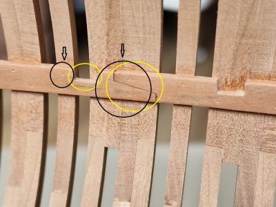
Hi, just for information, the parts marked Yellow should be placed in the areas circled in black.Frank

Alert 724.jpg
 
*Now everything is practically invisible, especially from a distance, but... this is before the oil coating. After the oil, everything will be clearly visible and imitation of bolts and nails and locks (already checked on the probes).

That is the dilemma we all face. We strive to make a model as historically accurate as possible, right down to all the nuts and bolts. Then you realize that there will be over 3000 of them! So we compromise with a simulated bolt. It still looks ok, but somehow you're a little disappointed in yourself. Then, when all the rest of the skeleton is built, you realize that unless you stick your eyeball right up to a gun port or hatchway, you can't even see all that work - and sometimes, not even then!

When I was building furniture, I tried to live by the motto, "The mark of a true craftsman is when all the parts that don't show look every bit as good as the parts that do." Of course, that was when I was younger and was planning on living forever. ROTF Now, I figure, if no one will see it unless they disassemble the model, I don't think it's worth the effort (or the time).
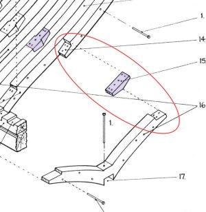
 
Hi, just for information, the parts marked Yellow should be placed in the areas circled in black.Frank

View attachment 523436
The position of the power board on which the beams are located is the parts from the kit. And I cannot move this board because the entire geometry of the beams position from the manufacturer will be violated. That is, these are the places that I cannot change, since the board is not an imitation but a real connection of boards from the kit. This applies only to the top board. The rest, there were no connections, I made an imitation as much as possible as it should be. Plus, I clarify once again that this board will be practically invisible because of the knees.
 
That is the dilemma we all face. We strive to make a model as historically accurate as possible, right down to all the nuts and bolts. Then you realize that there will be over 3000 of them! So we compromise with a simulated bolt. It still looks ok, but somehow you're a little disappointed in yourself. Then, when all the rest of the skeleton is built, you realize that unless you stick your eyeball right up to a gun port or hatchway, you can't even see all that work - and sometimes, not even then!

When I was building furniture, I tried to live by the motto, "The mark of a true craftsman is when all the parts that don't show look every bit as good as the parts that do." Of course, that was when I was younger and was planning on living forever. ROTF Now, I figure, if no one will see it unless they disassemble the model, I don't think it's worth the effort (or the time).
Amen, my friend! Your words are as if taken from my head! I absolutely agree with you. That if no one will see or practically will not see, then it is better to spend this time on something more necessary :D let's say on something that someone will see. ROTF
 
The position of the power board on which the beams are located is the parts from the kit. And I cannot move this board because the entire geometry of the beams position from the manufacturer will be violated. That is, these are the places that I cannot change, since the board is not an imitation but a real connection of boards from the kit. This applies only to the top board. The rest, there were no connections, I made an imitation as much as possible as it should be. Plus, I clarify once again that this board will be practically invisible because of the knees.
Thank you for replying to me, I took the liberty for the sake of information. Frank
 
Imitation of bolts on frames.

Continuing to the last post to close the issue with bots and insolences. It remains only to make bolts on the knees, but I will show this after trying on the beams of the lower deck.

Alert 732.jpg

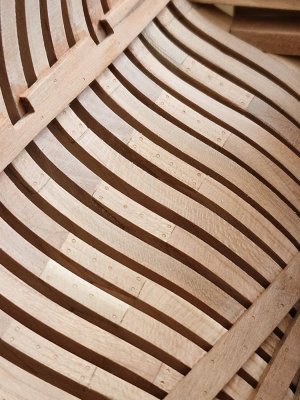
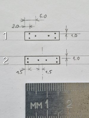
From the anatomy it can be seen that the bolts on the frame lock are placed in a certain way and judging by the options that I met on the forum, many did it as on the bottom diagram (first option).

Alert 733.jpg

But, I am inclined more towards my option (number two). Which is more practical with physical and mechanical properties. Since the bolts create a larger wrap shoulder, which strengthens the connection.

I created a small template by which I was able to make punctures (imitation of bolts) more or less repeatably the same way.

Alert 734.jpg

But, after several times, I could already do no worse by eye than according to the template, and things went faster.

I was mentally prepared that it would take a very long time. According to the calculation, punctures should be 3000. But! I also took into account those that are outside (we are still taking them away), and plus there are many more boards that block the bolt and there is no need to do it there. So, in 1.5 hours I made all the imitation bolts inside the case! And that's success. And looking at the result, I do not regret!

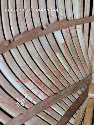
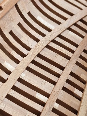
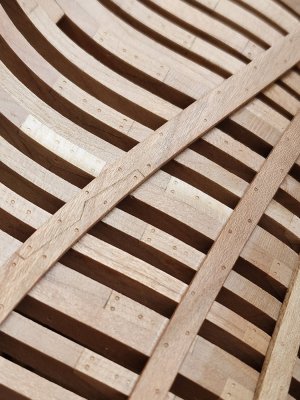
To see something, I used a flashlight and shone at an angle.

Alert 735.jpg

By the way, in the photo above - you can see the front 3 frames, which were without connections (and they should have been) and after I made an imitation of these connections - they fit perfectly into the surrounding view.

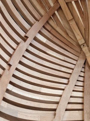
Without oil, all these punctures are very poorly visible. It was necessary to find such an angle so that at a certain angle of light the result was visible...

Alert 736.jpg

... but overall, I'm pleased with how it worked out.

Alert 737.jpg

Alert 738.jpg

Alert 739.jpg

So now, you can do the lower deck, hurray!

Ship-1
 
How did you make this pen? Just pull the ball out?
Absolutely right. I rubbed the tip at an angle, turning it on very fine sandpaper (1000) until the ball fell out. After that, you get a pointed cylinder. From time to time it needs to be cleaned, because it collects dust from the wood.
 
How did you make this pen? Just pull the ball out?
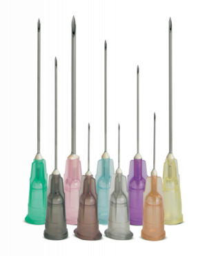
Sort of like using a hypodermic needle. :) From the below photo it is obvious with the needles the tips have to be ground down to get rid of the steep angle just as you had to sand until the ball fell out. Without a fine grinding wheel, your method looks to be easier, but I love when there are multiple solutions from which we can choose.
Allan
1749063063299.png
 
Last edited:
Sort like using a hypodermic needle. :) From the below photo it is obvious with the needles the tips have to be ground down to get rid of the steep angle just as you had to sand until the ball fell out. Without a fine grinding wheel, your method looks to be easier, but I love when there are multiple solutions from which we can choose.
Allan
View attachment 523571
The advantage of the pen method is, firstly, that it is more convenient to hold the pen in your hands and work with it. And secondly, the tip of the pen is already sharpened, you just need to remove the ball. And in the needle version, you need to not only cut off the sharp corner, but also sharpen the cylinder in a circle so that it does not press through the wood, deforming it, but as if it cuts the silhouette of the circle in a circle.
 
The only advantage I see with the needles is they come in a wide range of diameters. Otherwise, your method looks like a great way to go. Thanks for sharing.
Allan
 
I had some catching up to do Sergey. I like the way you present your build log, very clear and informative.

For now I wish you a very Happy Birthday Birthday-Cake.
I hope you can enjoy this day in the presence of family and friends.
 
З Днем народження, Сергію!
Бажаю міцного здоров’я, щастя, миру, успіхів у всіх починаннях і здійснення найзаповітніших мрій! Нехай кожен день приносить радість і натхнення! Героям слава! Обов’язково переможемо!
 
I had some catching up to do Sergey. I like the way you present your build log, very clear and informative.

For now I wish you a very Happy Birthday Birthday-Cake.
I hope you can enjoy this day in the presence of family and friends.
Thank you very much, ! I had a pleasant day with my family and your wish came true! ;)
Thank you for evaluating my review of the building. I am pleased to do it and pleased to hear a positive assessment.

Also from my side a Happy Birthday, Sergey. Enjoy this day!
Regards, Peter
Thanks, for the congratulations, Peter, very nice! :)

Happy birthday, Sergey! All the best to you for a joy-filled celebration!
Thank you, Paul so much for your congratulations!! ;)

Birthday wishes from me as well, my friend!
Thank you, Russ, I am pleased!

З Днем народження, Сергію!
Бажаю міцного здоров’я, щастя, миру, успіхів у всіх починаннях і здійснення найзаповітніших мрій! Нехай кожен день приносить радість і натхнення! Героям слава! Обов’язково переможемо!
Дякую, друже!! Дуже приємно читати рідною!!! Хояеться перемоги, миру і щоб все як найшвидше закінчилось. Ще раз дякую!! :cool:;)
 
Back
Top