• Win a Free Custom Engraved Brass Coin!!!
    As a way to introduce our brass coins to the community, we will raffle off a free coin during the month of August. Follow link ABOVE for instructions for entering.

HMS Alert [1777] 1:48 POF by serikoff. (Two hulls: skeleton and fully rigged)

But with one slip the wood is damaged. Can the bolt heads be made off the ship and then inserted?
I plan to try this. I'll form the caps separately, then remove them from the blank, and then insert them into the ship's hull. There's also an option to protect the hull from damage using a special thin plate with a hole for the wire, but I'll have to test everything.

But I also use very low RPMs and the bur's edge is smooth, so it's not easy to accidentally damage it without a purpose. At least, there was no accidental damage during testing.
 
Last edited:
Well, let's continue with our experiments and tests...

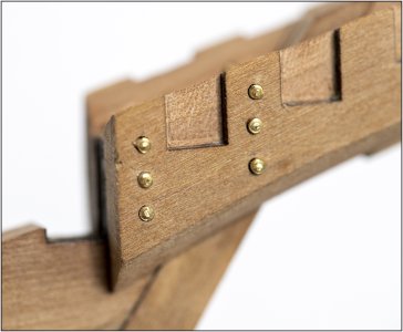
Today I'll show you some options for imitation bolts and nails on clinker.

View attachment 552423

The photo shows that the size suggested by the anatomy is clearly too large. The bolt head physically couldn't be 1.2-1.3 mm. That's simply enormous, considering the 0.5 mm head height. Therefore, studs with a 0.7 mm shank and a 1.2-1.3 mm head will definitely not work. This will look especially bad on the sheathing, where there's a taper of 4 mm.

Now a few words about mistakes. I specifically wanted to show them clearly, and how these errors will be visible, especially if you use bitumen.

View attachment 552425

1. Any cracks and crevices will be very visible after applying oil, and especially bitumen. Always keep this in mind.

2. The hole should be no larger than the dowel or wire. Otherwise, there will be a dark halo around it.

3. The bolt heads should be to scale (otherwise, you'll get a cucumber effect with its bumps). And ideally, all the nails and bolts should be as similar and identical in shape as possible (this will at least look prettier and neater).

A quick option is to glue the nail or wire into the board and then cut it off and sand it flush with the boards... but I don't like this visually, although it's good and simple.

I like it when the dowel or wire protrudes slightly above the surface, creating some texture, but only very slightly. So, I initially did it like this:

View attachment 552426

I drilled a 1 mm hole, inserted a 1 mm wire into it, and snipped it off with wire cutters, leaving 0.5 mm. Then I sanded it down. This way, the wire protruded slightly above the surface, but was rounded.

View attachment 552427

I liked the 0.8mm wire option better than the 1mm wire; it looked more natural, but...

... I bought special cup-shaped burs:

View attachment 552428

These burs come in various sizes, from 0.8 mm upwards. I noticed that the 0.8 mm burr worked very well on nails with a diameter of 0.5 mm, but when used on 0.8 mm wire, the results weren't very visible.

View attachment 552429

That is, even under magnification, any geometry of the head is barely visible. It just looks like the wire has been scratched, but on 1 mm wire, this burr works wonders, in my opinion!

View attachment 552430

In the photo above, you can see that the polished 1mm wire looks ordinary and unnatural (although this result is very easy to achieve).

But after burring, a clear bolt head profile appears!

Yes, you need to control the center when positioning—otherwise, the bolt head may be off-center, but this is mainly due to haste and the uneven surface of the wire before burring. But I really liked the result. And most importantly, it's very quick and repeatable!

View attachment 552431

So, to summarize, the current plan is to make a test piece and perform the following manipulations on it: use a 1 mm diameter burr to process the 1 mm wire, and use a 0.8 mm burr to process the nails (0.5 mm birch toothpicks) (since that's the smallest).

And here's the planned result, very enlarged:

View attachment 552432

I love how fast, repeatable, and easy this method is. It only takes a few steps: mark the hole with a needle, drill, insert the wire, cut it, and lightly sand it with fine sandpaper to remove the sharp edges. Then, use the burr to create the cap, which takes about a second... hmm...
Those burrs are great, Sergey. 'It's all in the details'.
Used them also on my Bluenose after a tip from Maarten @Maarten and Jim @Jimsky on there Alert builds:
100 Burr.jpg
Regards, Peter
 
Those burrs are great, Sergey. 'It's all in the details'.
Used them also on my Bluenose after a tip from Maarten @Maarten and Jim @Jimsky on there Alert builds:
View attachment 552483
Regards, Peter
Yes, I saw this technology over 15 years ago, and when I was studying all the Alert threads, I saw it in the modelers you mentioned. They, like you, implemented this method perfectly. So, I made a small contribution. ;)
 
I had not seen this before but look forward to trying it. Looks great, especially at our larger common scales.
Allan
Thank you, glad to try. :cool:

How its called and where to buy it in EU market?
Search for ‘Cup Burrr’ and you found a lot of them in different shapes and sizes:
View attachment 552547
Regards, Peter
Yes, they come in different sizes, and generally, if the size is 0.8 mm, it means the bur is suitable for 0.8 mm wire, and so on. A 2.35 mm shank diameter is the standard for dental miuromotors, but logically, other diameters should be available. The main thing is to set the motor speed low to have more control and avoid damaging the part. I've shown what the cup itself looks like in the photo, and I can say that it's best to choose one with slots to prevent the chips from clogging the bur.
 
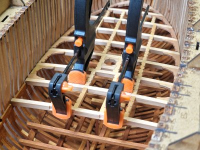
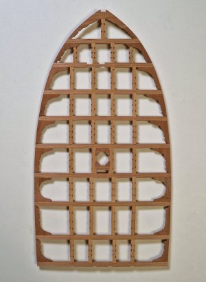
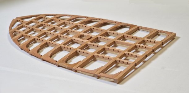
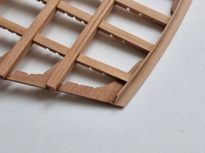
Continuing with the deck... today I managed to complete three spans at once.

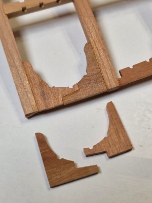
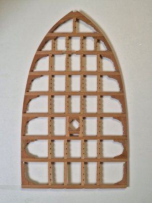
The new additions are the prefabricated knees that connect the front and back of the deck.

Alert 1448.jpg

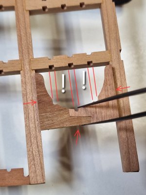
The important thing here is to connect them so that the connection itself is in the right place, and the edges of the connection with the beams are precise, but it is also important that the grooves on the carlings and knees match, so that the partitions are parallel to each other.

Alert 1449.jpg

Alert 1450.jpg

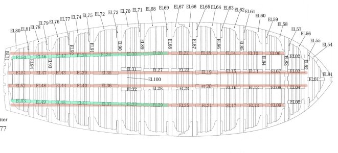
The second point is that almost all the carlings run parallel to the ship's axis (highlighted in red in the diagram below). However, the outer carlings, from the middle to the stern, run at an angle (marked in green in the diagram). This is important, as the carlings now need to be prepared in pairs (two middle and two side ones, ground at a slight angle).

Alert 1450в.jpg

Well, everything else remains unchanged... first I glue the carlings to the beams and then glue the knees outside the hull.

Alert 1451.jpg

Alert 1452.jpg

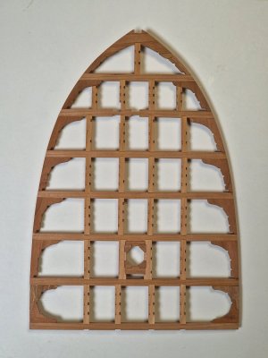
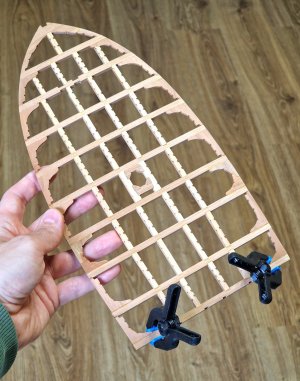
The deck keeps growing and growing... and this is what it looks like relative to my hand.

Alert 1453.jpg

I'm one span and 2/3 are already ready...

Alert 1454.jpg

Alert 1455.jpg

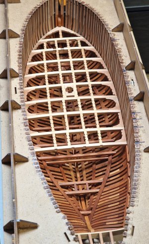
And here's how it looks in the ship's hull... in first!

Alert 1456.jpg

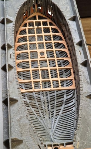
But it's also no small matter that she easily fits into the ship's second hull...

Alert 1457.jpg

...and what a shame it can't be cloned. CautiousROTF

We'll have to make a simplified version for the second hull, so we can then cover the entire deck with planks.
 
Continuing with the deck... today I managed to complete three spans at once.

The new additions are the prefabricated knees that connect the front and back of the deck.

View attachment 552740

The important thing here is to connect them so that the connection itself is in the right place, and the edges of the connection with the beams are precise, but it is also important that the grooves on the carlings and knees match, so that the partitions are parallel to each other.

View attachment 552741

View attachment 552742

The second point is that almost all the carlings run parallel to the ship's axis (highlighted in red in the diagram below). However, the outer carlings, from the middle to the stern, run at an angle (marked in green in the diagram). This is important, as the carlings now need to be prepared in pairs (two middle and two side ones, ground at a slight angle).

View attachment 552743

Well, everything else remains unchanged... first I glue the carlings to the beams and then glue the knees outside the hull.

View attachment 552744

View attachment 552746

The deck keeps growing and growing... and this is what it looks like relative to my hand.

View attachment 552747

I'm one span and 2/3 are already ready...

View attachment 552748

View attachment 552749

And here's how it looks in the ship's hull... in first!

View attachment 552750

But it's also no small matter that she easily fits into the ship's second hull...

View attachment 552751

...and what a shame it can't be cloned. CautiousROTF

We'll have to make a simplified version for the second hull, so we can then cover the entire deck with planks.
That’s looking very nice, Sergey.
I suggest scan the deck and then print it. A little sanding and painting, and you have the second deck.;)
Regards, Peter
 
That’s looking very nice, Sergey.
I suggest scan the deck and then print it. A little sanding and painting, and you have the second deck.;)
Regards, Peter
That's what I thought at first... but this time the costs will be greater than the results. I'll make it simpler. I have some scrap left over from milling the beams, and there are precise profiles of these beams. I'll use them to cover the deck with rough planking, and then I'll glue the deck boards on top. I need a rigid base so I can sand the deck later, and it won't take long. I'll tell and show you all about this; you'll like it.
 
Hey Sergey,

once again very nicely realised! Building at this scale has its definite advantages. I build smaller. The drills are really great. Unfortunately too big in my scale 1/72 to 1/84. Thanks for showing them though!
 
As always, your work is impeccable and a beauty to behold !
Thank you very much. It's become more difficult to work and shoot now because it gets dark early, it's often cloudy, and there's not enough light to see everything comfortably. Nothing can replace the sun. :cool:

Hey Sergey,

once again very nicely realised! Building at this scale has its definite advantages. I build smaller. The drills are really great. Unfortunately too big in my scale 1/72 to 1/84. Thanks for showing them though!
Thanks for the feedback. For me, there's no point in adding detail when the scale is higher than 1:70. Sometimes, even at a larger scale, things are hard to see, but you're right... 1:48 is just the right scale to show a lot... but it also means more work. ;)
 
We're continuing the photo report. Nothing's changed, so I'm only showing progress.

Alert 1458.jpg

Alert 1459.jpg

Alert 1460.jpg

Almost finished... two more spans and one beam left.

Alert 1461.jpg

Alert 1462.jpg

There will be one issue at the very end, since the final beam is already glued in place and the cleats need to be reinforced to ensure they are held in place while polishing the deck away from the hull, but more on that next time... ;)
 
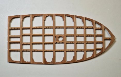
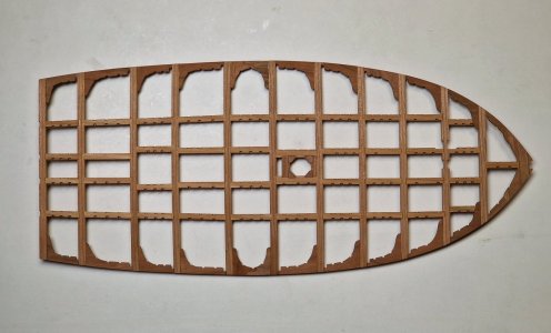
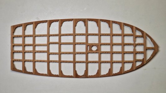
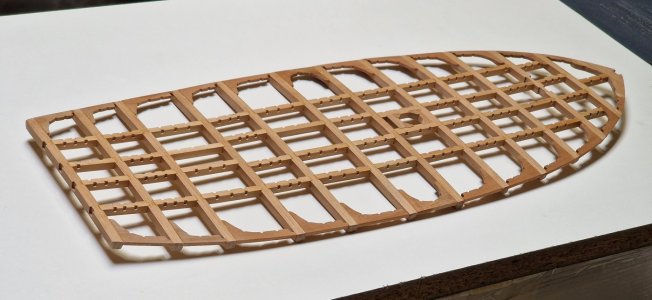
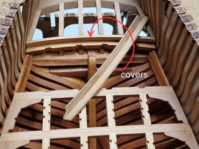
Continuing with the upper deck.
And finishing with the penultimate beam...
Alert 1463.jpg

Everything here remains unchanged, but things get more interesting further down.

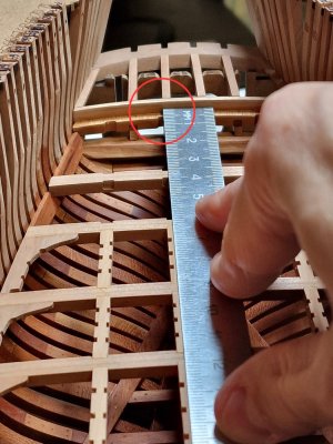
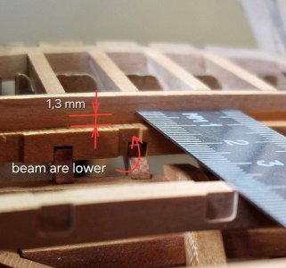
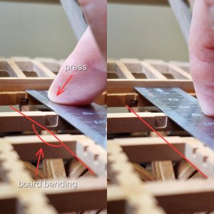
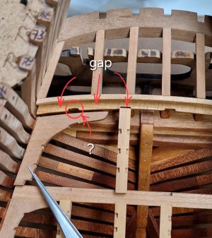
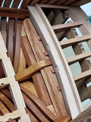
The last beam was already part of the hull, and it ended up lower than it should have been...
Alert 1464.jpg

The place in the red circle is closer:

Alert 1465.jpg

1.3 mm is a lot to ignore, because if the boards on this model were nailed, there would be a bend in them.

Alert 1466.jpg

And since I'll have deck planks on the second hull (and the hulls are exactly the same), I need to calculate everything here and repeat the same steps to ensure the deck planks are aligned correctly.

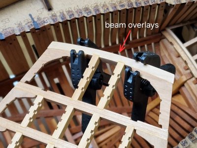
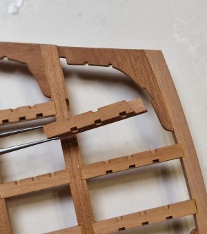
But that's not all... The beam ended up being further from the second-to-last one, and the keels and knees didn't reach it...
Alert 1467.jpg

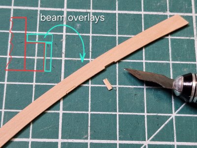
Therefore, I decided to make an overlay on the beam, increasing its height and width.

Alert 1468.jpg

The picture above shows the profile of this escutcheon in green. This is actually beneficial, since the deck is removable and the final carlings and knees would be fragile without the final beam, so the escutcheon will strengthen the structure at the end.

Alert 1469.jpg

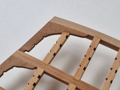
Yes, unfortunately the place where the top and side panels connect will be a little visible...

Alert 1470.jpg

...but almost all of this space will be covered by knees and carlings.

Alert 1471.jpg

The side carligni here are a little more complex in shape, which are placed under the knee.

Alert 1472.jpg

Alert 1473.jpg

Alert 1474.jpg

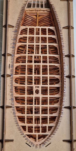
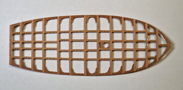
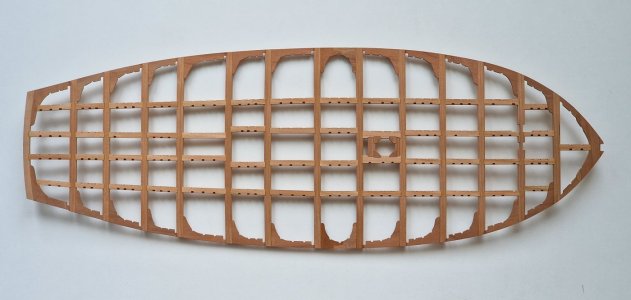
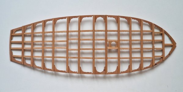
Well, here's what the entire deck looks like from both sides (without crossbars and without sanding yet).

Alert 1475.jpg

Alert 1476.jpg

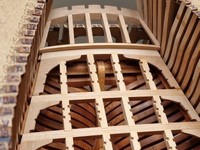
The rear section of the hull looks like this. (The gaps between the deck and the hull are larger than necessary, but otherwise the deck wouldn't be able to be removed. These gaps will be covered by the waterway, and that's where the glue will be to secure the deck in place after its final positioning.)

Alert 1477.jpg

More than 100 parts and here is the result in the case (not glued yet).

Alert 1478.jpg

Alert 1479.jpg

Alert 1480.jpg

Now comes the big work of removing excess glue, rough sanding, and then securing the Ledges. I haven't yet decided how I'll implement it all... but more on that later.
 
Very nice and careful work, Sergey. I appreciate the alignment of the carlings along the length of the ship. Well done, my friend!

Several times you have mentioned the 'removability' of this deck. Are you talking about during the construction phase? I assume you will be permanently installing everything when you add the hanging knees? Or will the knees be allowed to "hang free" because there is no interior planking thus truly making the deck removable?
 
Last edited:
Back
Top