Beautiful work Dave. This is not your first rodeo.
-

Win a Free Custom Engraved Brass Coin!!!
As a way to introduce our brass coins to the community, we will raffle off a free coin during the month of August. Follow link ABOVE for instructions for entering.
-

PRE-ORDER SHIPS IN SCALE TODAY!
The beloved Ships in Scale Magazine is back and charting a new course for 2026!
Discover new skills, new techniques, and new inspirations in every issue.
NOTE THAT OUR FIRST ISSUE WILL BE JAN/FEB 2026
- Home
- Forums
- Ships of Scale Group Builds and Projects
- Group Build Archives
- Blandford Cross Section PoF Group Build
You are using an out of date browser. It may not display this or other websites correctly.
You should upgrade or use an alternative browser.
You should upgrade or use an alternative browser.
Thanks, Mike! Your build is looking great. I think you’ll finish the first Blandford Cross Section after Mike’s prototype. Keep going!
Hi Everyone, Question, on the bits on the detail sheet in shows the horizantal member being 1/8 inch square, on the framing plan and on SHTMIK (MIKE) build it looks like a 1/4 inch square witch is it. THANKS Don
- Joined
- Aug 10, 2017
- Messages
- 1,706
- Points
- 538

Hi Don,Hi Everyone, Question, on the bits on the detail sheet in shows the horizantal member being 1/8 inch square, on the framing plan and on SHTMIK (MIKE) build it looks like a 1/4 inch square witch is it. THANKS Don
The Bitts are 1/8” thick and ¼” wide, the horizontal piece is inset in the vertical pieces 1/32” as shown in the detail. I hope this helps.
Mike
I am ready to glue the stakes and footwaling in but mine do nt match the size of the ones on the plans. I cut them per the bom. The stakes are 3/8, footws are 3/32, and 1/4. Am i wrong or the plans. Need help.
Is it possible that the 3/32 footw is really 3/16? If it is that would clear it up for me.
Hi Pawley: Yup, the footwalling is 3/16" wide. The strakes, or "thick stuff" were designed to reinforce the futtock butt joints and should more or less overlie those joints on the frame. I was a little less than fastidious with my locating the thick stuff.
The general principle here is build to the plans, not the Bill of Materials. Do not hesitate to ask questions, though!
The general principle here is build to the plans, not the Bill of Materials. Do not hesitate to ask questions, though!
Thanks Dave. I'm going pay more attention to the plans, for sure. So back to the saw to rip up some wood.
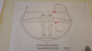
I have a question about the pump dale outlet. The outlet is shown coming out of the Wales at frame 5. The pump dale from the chain pump is at frame 6. Is this because there is a sweep port above on frame 6? The AofS book shows the same placement. Just thinking before I drill.
The plans and the AOTS book both show the dales exactly perpendicular to the centerlione of the ship. The plans say the outlet should be at frame 6, but the outboard planking plans show the scupper at frame 5. Not sure how the discrepancy came about!I have a question about the pump dale outlet. The outlet is shown coming out of the Wales at frame 5. The pump dale from the chain pump is at frame 6. Is this because there is a sweep port above on frame 6? The AofS book shows the same placement. Just thinking before I drill.
That's exactly what I thought, Mike! 
There isn't room to move the chain pump housing toward frame 5, and angling the dales wouldn't look right, so I guess I'd leave the dales ending at frame 6 and the discharge outlet at frame 5.
There isn't room to move the chain pump housing toward frame 5, and angling the dales wouldn't look right, so I guess I'd leave the dales ending at frame 6 and the discharge outlet at frame 5.
I hate printer malfunctions Thanks Dave.
Guys:
What is the best technique for trimming the frame tops? Razor saw, Dremel with a rotary saw? Obviously keeping the trim line accurate and flat, parallel to the deck is most important
What is the best technique for trimming the frame tops? Razor saw, Dremel with a rotary saw? Obviously keeping the trim line accurate and flat, parallel to the deck is most important
Hi Dave, I am using a miniature razor saw, very smooth cut and doesn't break\splinter wood. I am not cutting single frame, but rather angle an take the adjacent frame as well. This way you cut even.
Hey, Jim!
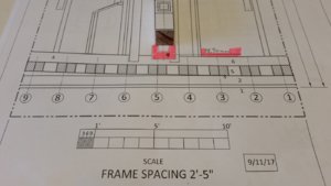
Can I ask a favor? Can you measure how high the cut line is above the surface of the deck beams (not the planking) at frame 1 and frame 9? If you go according to the longitudinal view of the plans, those numbers are 7/8" and 1-1/32"
Can I ask a favor? Can you measure how high the cut line is above the surface of the deck beams (not the planking) at frame 1 and frame 9? If you go according to the longitudinal view of the plans, those numbers are 7/8" and 1-1/32"
Dave,
Not sure if this question to correct Jim, as I don't have any models to measure frames. A razor blade can cut 5.8mm deep and has a length of 37.5mm (if this help)
Not sure if this question to correct Jim, as I don't have any models to measure frames.
Sorry, Jim. My mistake!
- Joined
- Dec 3, 2018
- Messages
- 2,451
- Points
- 538

Help with measurements.
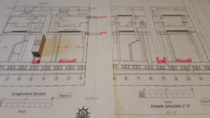
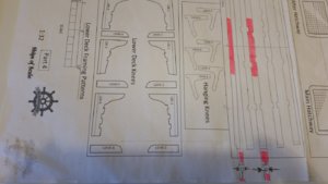
Here are some pictures that I have targeted.
1-mast foot.
Two pictures, I assume it is the first one that has the right goal.


2- Deck beam, from these drawings it looks like the different thickness and height of these beams.


Since I do not have so much material left with this length, I do not want to make them wrong .
If anyone out there can measure Upper and Lower deck beams in (mm), height - thickness, 1-32.
I am very happy if someone can take some time to help me with this problem.
Greeting-
Here are some pictures that I have targeted.
1-mast foot.
Two pictures, I assume it is the first one that has the right goal.


2- Deck beam, from these drawings it looks like the different thickness and height of these beams.


Since I do not have so much material left with this length, I do not want to make them wrong .
If anyone out there can measure Upper and Lower deck beams in (mm), height - thickness, 1-32.
I am very happy if someone can take some time to help me with this problem.
Greeting-


