You are using an out of date browser. It may not display this or other websites correctly.
You should upgrade or use an alternative browser.
You should upgrade or use an alternative browser.
HMS Druid P.O.F. - Unicorn Models by Donnie [COMPLETED BUILD]
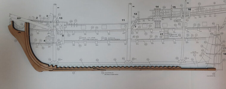
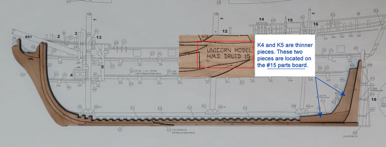
Hi Donnie, is it just how the keel pieces are lying loose or is there a slight scale difference between the parts and the plans? Looks like the stern end of the keel is longer then the plans.
Hi Chris,
not all the pieces are there. Yes, there are more stern pieces to add. I was just wrapping up the evening and came to a stop. I had a feeling that someone was going to question this... !!!
not all the pieces are there. Yes, there are more stern pieces to add. I was just wrapping up the evening and came to a stop. I had a feeling that someone was going to question this... !!!
Hi Donnie,
Just a little late to the show - would you mind if I join in the viewing party?
Paul
Just a little late to the show - would you mind if I join in the viewing party?
Paul
Hi Paul,
Absolutely. I hope that I can document this build well in case others want to build it. I am trying to cover all the “gotchas”.
Absolutely. I hope that I can document this build well in case others want to build it. I am trying to cover all the “gotchas”.
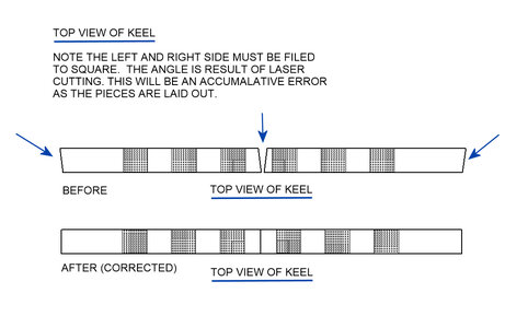
Again, the curse of the laser !!!!
And furthermore. Each Keel notch will have to be filed or use a Mill to make each notch square. Not that it is a really big deal, but just something that has to be done. The notches are tight and that is a good thing (if there were square). However, since they are not square, what happens is that the frames (when inserted onto keel), will be WAY off - therefore this has to be corrected. Filing is sloppy for this, so I will have to set up the Mill for this operation. This is one of those things that has to be done right off the start, or the rest of the build will suffer - just a little attention to detail will make a huge difference when inserting the some 45 to 50 frames.
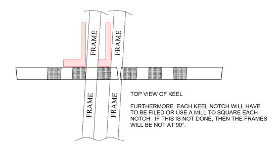
Looking down on the keel.
I am using a piece of scrap that is the SAME width as the Frames. When a frame is inserted into a notch, as you see, the frame (scrap) is not square. Therefore the notches will have to have some machining done or some filing as you must have the frames sit square.
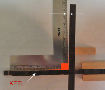
And furthermore. Each Keel notch will have to be filed or use a Mill to make each notch square. Not that it is a really big deal, but just something that has to be done. The notches are tight and that is a good thing (if there were square). However, since they are not square, what happens is that the frames (when inserted onto keel), will be WAY off - therefore this has to be corrected. Filing is sloppy for this, so I will have to set up the Mill for this operation. This is one of those things that has to be done right off the start, or the rest of the build will suffer - just a little attention to detail will make a huge difference when inserting the some 45 to 50 frames.

Looking down on the keel.
I am using a piece of scrap that is the SAME width as the Frames. When a frame is inserted into a notch, as you see, the frame (scrap) is not square. Therefore the notches will have to have some machining done or some filing as you must have the frames sit square.

That is not good QA from Unicorn Models.
I'm building their mini 1/128 version of this kit in sections, there is not so much cut angle issue with the laser on the smaller kits because the pieces are so thin it doesn't matter.
There are issues with a 'wavy' laser- but with pieces being so small they can easily be filed straight without too much effort.
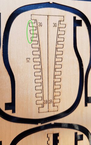
Your kit problems seems to need a whole lot more work to have them rectified.
I'm building their mini 1/128 version of this kit in sections, there is not so much cut angle issue with the laser on the smaller kits because the pieces are so thin it doesn't matter.
There are issues with a 'wavy' laser- but with pieces being so small they can easily be filed straight without too much effort.

Your kit problems seems to need a whole lot more work to have them rectified.
- Joined
- Dec 1, 2016
- Messages
- 5,128
- Points
- 728

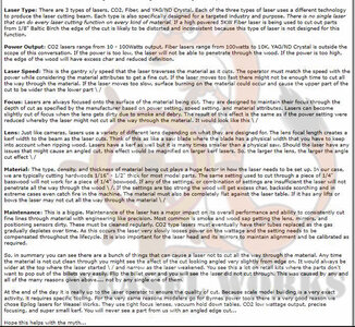
the issue with the laser cuts is not Unicorn Models it is common for all lasers. What is going on is the laser beam spreads out like this /\ the focus of the beam is on the surface of the material and as it exits at the bottom the beam is slightly out of focus so it spreads out.
That is correct Dave, this not about the Unicorn Models.
Wang
I will move your images to the "SOS Scratch or Plans Build Logs" however, what is the name of the ship that you are building that you show the photos? I can help you start the Build Log TITLE.
I will move your images to the "SOS Scratch or Plans Build Logs" however, what is the name of the ship that you are building that you show the photos? I can help you start the Build Log TITLE.
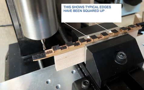
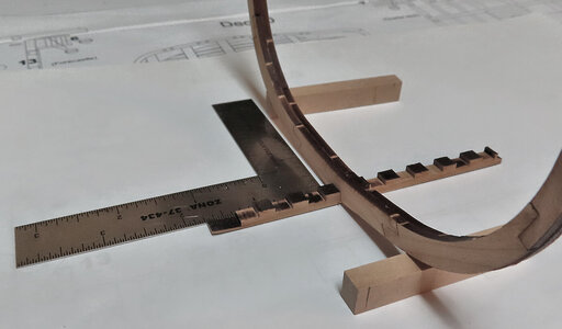
The images now show that I used my Mill to square up the faces or edges of the Keel. There are three sections to clean up. It only took about 15 minutes per section to clean up. However, if you are doing something like this for the first time, I suggest that you plan ahead and go very slowly. You will notice that I use a block of wood under the keel. This block of wood is very important. I am able to use the block of wood as a flat support surface and at the same time the jaws of the vice keeps the keel locked down. However, this is the important point. You DO NOT want the PRESSURE of the down force of the Mill to push down on the stock you are working on. This is the purpose of the block of wood. You always MUST have a secure flat stable environment for Milling. Like I have always said, it takes more time to setup to make a cut than the cut actually takes. I am not being some safety geek. I am saying this as this is the proper way of doing things and you certainly do not want to damage the piece you are working on. You work with wood LIKE YOU are working with metal - SAME RULES apply !!!!
I am using a down-cut End Mill for wood use. The down-cut End Mill makes for a nice clean cut that will not fray the wood. The End Mill was bought from https://www.2linc.com/ Part # PWD2-125-1 @ about $15 each This End Mill should be able to fit on the Proxxon Mill as well. The shank is 1/8 inches (.125 inches) or 3.175mm
The last image shows a frame inserted on the Keel and the job is well done.


Hallo my friend,
I am very happy, that you started a new project - and a very interesting one
I will follow with big interest
I am very happy, that you started a new project - and a very interesting one
I will follow with big interest
I might add that laser cutting might not be much of a problem for POB kits. But, with small frame (rib) parts and the keel, then this is different. No complaints. I know that CNC is coming upon us, but not everyone has or can embrace the CNC. Also, laser cutting is a science in itself such as maintaining equipment and making sure the laser beam is focused as it should. Then the thickness of the material has a lot to do with it as well. Thinner material is not going to reproduce an angle to the cut, whereas thicker material means more angle - it's all in the math of angles and such. The thicker the material, the wider the angle is going to be. Lastly, the position of the part that is being cut out. Just my 2 cents. It is what it is. Just have to work with what you got. No problem.
- Joined
- Dec 1, 2016
- Messages
- 5,128
- Points
- 728

I might add that laser cutting might not be much of a problem for POB kits. But, with small frame (rib) parts and the keel, then this is different. No complaints. I know that CNC is coming upon us, but not everyone has or can embrace the CNC. Also, laser cutting is a science in itself such as maintaining equipment and making sure the laser beam is focused as it should. Then the thickness of the material has a lot to do with it as well. Thinner material is not going to reproduce an angle to the cut, whereas thicker material means more angle - it's all in the math of angles and such. The thicker the material, the wider the angle is going to be. Lastly, the position of the part that is being cut out. Just my 2 cents. It is what it is. Just have to work with what you got. No problem.
both laser cutting and CNC have their pros and cons and your right laser cutting is a science in itself. from what i see in your build log a lot of design and thought went into this kit and the overall results make a top notch product and for the price it is really hard to beat.
so what i did is ask experts in laser cutting to give me their views. so here it is, notice in the back round the faint watermark. This is done because of a group with no ethical values that will steal other forums post and property with screen shots without asking permission. It is a shame this has to be done and why information can not be openly shared but it is what it is.
Thank you Donnie, you build many carefully than I. I build name is "HMS druid1776"Wang
I will move your images to the "SOS Scratch or Plans Build Logs" however, what is the name of the ship that you are building that you show the photos? I can help you start the Build Log TITLE.
Canoe21
Lawrence
Hello Donnie, You ack like you are a pro with your mill, as you have did a very nice clean job.The images now show that I used my Mill to square up the faces or edges of the Keel. There are three sections to clean up. It only took about 15 minutes per section to clean up. However, if you are doing something like this for the first time, I suggest that you plan ahead and go very slowly. You will notice that I use a block of wood under the keel. This block of wood is very important. I am able to use the block of wood as a flat support surface and at the same time the jaws of the vice keeps the keel locked down. However, this is the important point. You DO NOT want the PRESSURE of the down force of the Mill to push down on the stock you are working on. This is the purpose of the block of wood. You always MUST have a secure flat stable environment for Milling. Like I have always said, it takes more time to setup to make a cut than the cut actually takes. I am not being some safety geek. I am saying this as this is the proper way of doing things and you certainly do not want to damage the piece you are working on. You work with wood LIKE YOU are working with metal - SAME RULES apply !!!!
I am using a down-cut End Mill for wood use. The down-cut End Mill makes for a nice clean cut that will not fray the wood. The End Mill was bought from https://www.2linc.com/ Part # PWD2-125-1 @ about $15 each This End Mill should be able to fit on the Proxxon Mill as well. The shank is 1/8 inches (.125 inches) or 3.175mm
The last image shows a frame inserted on the Keel and the job is well done.
View attachment 204869
View attachment 204870
Regards Lawrence
@Lawrence Thank you - it takes just a little time invested to learn a little goes a long way.
@Dave Stevens (Lumberyard) Thank you for that article. That explains a lot. No complaints, just working around a little problem here and there.
@Uwek Thanks for following - Now, I am getting even more nervous with all these experts following.
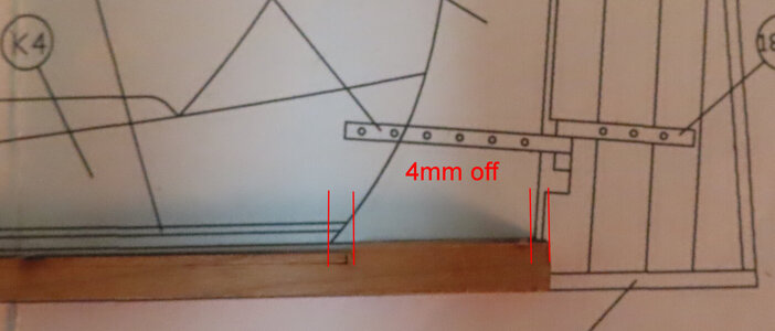
Ok, so, while I have some more frames drying up, I wanted to turn my attention to the Keel. The initial fitment had the Keel at 4mm too long per plans - well, almost 5mm. However taking into account the laser cut situation, I felt that squaring those off would probably solve that problem and it did.
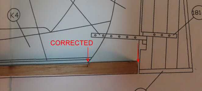
I just used my Mill to square off ALL the faces of the scarf joints. This operation was literally just less than 10 min to do. When performing this operation, you really only want to see "the dust' of the faces to be trimmed. If you see more than "wood dust" coming off the faces, then you need to seriously back off the machine. We are only talking less than .10 mm per pass. That is 1 hundredth of one millimeter or 3 thousandths. Removing about .3mm from each joint will make the total length of the Keel be in agreement with the plans. In inches that is about 11 thousandths off of each scarf joint.
That might seem insignificant. But just want to put those scarf joints back together and you will see that it does not take much. Sorry that I did not post images of the Mill in action.
The rest of the build will probably NOT need this type of attention - the part of the build is the core of how things will make good alignment for the future of the build.
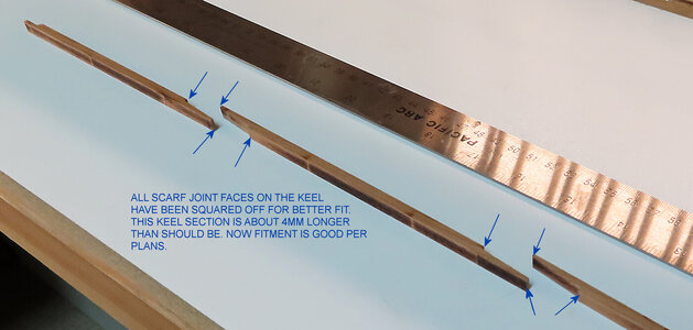
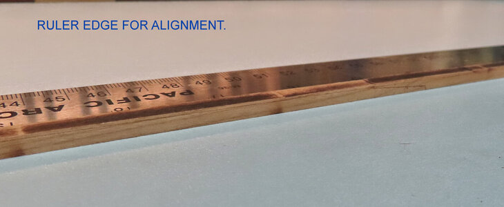
Here the parts are laid out on a nice flat "shelf" and using a ruler for a "backing" to make sure the glue-up will be right. Pretty nice scarf joints - the Mill did well.
BEFORE the Mill cuts
AFTER the MIll Cuts. The length of the Keel is now per plans - again, squaring off the scarf "faces" REDUCED the length of Keel. You can not just chop the end off as this will distort how the stern pieces will fit - the adjustments has to be made to the scarf joints to make each end of the Keel make alignment properly.
@Dave Stevens (Lumberyard) Thank you for that article. That explains a lot. No complaints, just working around a little problem here and there.
@Uwek Thanks for following - Now, I am getting even more nervous with all these experts following.
Ok, so, while I have some more frames drying up, I wanted to turn my attention to the Keel. The initial fitment had the Keel at 4mm too long per plans - well, almost 5mm. However taking into account the laser cut situation, I felt that squaring those off would probably solve that problem and it did.
I just used my Mill to square off ALL the faces of the scarf joints. This operation was literally just less than 10 min to do. When performing this operation, you really only want to see "the dust' of the faces to be trimmed. If you see more than "wood dust" coming off the faces, then you need to seriously back off the machine. We are only talking less than .10 mm per pass. That is 1 hundredth of one millimeter or 3 thousandths. Removing about .3mm from each joint will make the total length of the Keel be in agreement with the plans. In inches that is about 11 thousandths off of each scarf joint.
That might seem insignificant. But just want to put those scarf joints back together and you will see that it does not take much. Sorry that I did not post images of the Mill in action.
The rest of the build will probably NOT need this type of attention - the part of the build is the core of how things will make good alignment for the future of the build.

Here the parts are laid out on a nice flat "shelf" and using a ruler for a "backing" to make sure the glue-up will be right. Pretty nice scarf joints - the Mill did well.

BEFORE the Mill cuts

AFTER the MIll Cuts. The length of the Keel is now per plans - again, squaring off the scarf "faces" REDUCED the length of Keel. You can not just chop the end off as this will distort how the stern pieces will fit - the adjustments has to be made to the scarf joints to make each end of the Keel make alignment properly.

very nice work so far

