
Thank you all. It seems my camera is not taking pictures as sharp as it used to. I am not sure if it is the lighting or what - but I have done much better in the past than now. I did not realize just how bad they were until I got at my office and looked at them on my better monitor. Yuk.

You are using an out of date browser. It may not display this or other websites correctly.
You should upgrade or use an alternative browser.
You should upgrade or use an alternative browser.
HMS Druid P.O.F. - Unicorn Models by Donnie [COMPLETED BUILD]
Ok, so this next step, I had to do a lot of studying the pictures in the manual. The English translation is nearly impossible to follow for this step - so the pictures in the manual were the only thing I had to go by and the images were not that good. So, therefore, this is the reasoning that I came up with and I hope that it is all correct. The parts seem to fit fairly well, but the poop support beam needed a little more shaping to make it fit correctly.


I appreciate the precision you are bringing to this build and the helpful explanations - this log will be an indispensable help to future builders.

Outstanding visuals. Your pictures describe the assembly to a tee. Who needs instructions. Haha Aloha, MikeJ
It is looking very good - and clear fully understandable photos
- so everybody how will build the same model can follow your thoughts and work easily
- so everybody how will build the same model can follow your thoughts and work easily
I am finished with constructing the major portion of the ribs and frames and other components. Please read this statement below as according to the manual, the hull planking should commence. According to my study, this should not be the case.
CASE 1:
PLEASE REVIEW MY POST #141 AS I MISCALCULATED THE PLACEMENT OF SOME SPACERS NEAR THE BOW. THE LOWER SPACERS ARE SITTING TOO LOW. WHEN THE FEW STRIPS OF PLANKING ARE LAID ON THE LOWER HULL, THESE SPACERS WILL BE SEEN AND THAT IS NOT GOOD. SO, THEREFORE, PLEASE READ MY STATEMENT AT POST #141. I APOLOGIZE FOR THIS ERROR AND I HOPE THAT THOSE FOLLOWING AND BUILDING THIS MODEL WILL NOT FALL INTO THE SAME SITUATION.
CASE 2:
THE INSTRUCTIONS CALL FOR ALL THE HULL PLANKING TO BE DONE (HOWEVER, THE LOWER 1/2 OF THE RIBS ARE VISIBLE - NO, THE ENTIRE LOWER HULL IS NOT PLANKED. HOWEVER, ANY PART OF THE HULL SHOULD NOT BE PLANKED AT THIS TIME. THE REASON IS THAT IF YOU DO, THEN THE REFERENCE MARKS FOR THE LOWER FLOOR AND UPPER FLOOR BEAMS WILL BE CONCEALED AND YOU WILL NOT BE ABLE TO SEE THE REFERENCE MARKS. THIS IS ANOTHER PROBLEM I SEE.
THEREFORE, MY IDEA IS TO INSTALL THE LOWER FLOOR BEAMS AND THEN PLANK THE LOWER MOST HULL, THEN WORK MY WAY UP.
To me, I must confess that this model is very difficult. What makes this model difficult? The model according to the manual goes against what I think is normal protocol for building a model. Next, the China to English translation is very poor. There are NO Chinese words in their language to express basic ship terms even the word "plank" or "hull" in its proper terms. Now let me say this. The QUALITY of the model and wood is superb !!!! The finished product will be outstanding that is if I can master the barriers I am faced with.
Last edited:


The model is looking great. Regarding order of building, I've found myself in similar situation. In the number of reference books on POF and wonderful logs we have here at SOS, at this point it is recommended to install deck clamps and then move outwards. I'm sure you'll do outstanding job.I am finished with constructing the major portion of the ribs and frames and other components. Please read this statement below as according to the manual, the hull planking should commence. According to my study, this should not be the case.
CASE 1:
PLEASE REVIEW MY POST #141 AS I MISCALCULATED THE PLACEMENT OF SOME SPACERS NEAR THE BOW. THE LOWER SPACERS ARE SITTING TOO LOW. WHEN THE FEW STRIPS OF PLANKING ARE LAID ON THE LOWER HULL, THESE SPACERS WILL BE SEEN AND THAT IS NOT GOOD. SO, THEREFORE, PLEASE READ MY STATEMENT AT POST #141. I APOLOGIZE FOR THIS ERROR AND I HOPE THAT THOSE FOLLOWING AND BUILDING THIS MODEL WILL NOT FALL INTO THE SAME SITUATION.
CASE 2:
THE INSTRUCTIONS CALL FOR ALL THE HULL PLANKING TO BE DONE (HOWEVER, THE LOWER 1/2 OF THE RIBS ARE VISIBLE - NO, THE ENTIRE LOWER HULL IS NOT PLANKED. HOWEVER, ANY PART OF THE HULL SHOULD NOT BE PLANKED AT THIS TIME. THE REASON IS THAT IF YOU DO, THEN THE REFERENCE MARKS FOR THE LOWER FLOOR AND UPPER FLOOR BEAMS WILL BE CONCEALED AND YOU WILL NOT BE ABLE TO SEE THE REFERENCE MARKS. THIS IS ANOTHER PROBLEM I SEE.
THEREFORE, MY IDEA IS TO INSTALL THE LOWER FLOOR BEAMS AND THEN PLANK THE LOWER MOST HULL, THEN WORK MY WAY UP.
To me, I must confess that this model is very difficult. What makes this model difficult? The model according to the manual goes against what I think is normal protocol for building a model. Next, the China to English translation is very poor. There are NO Chinese words in their language to express basic ship terms even the word "plank" or "hull" in its proper terms. Now let me say this. The QUALITY of the model and wood is superb !!!! The finished product will be outstanding that is if I can master the barriers I am faced with.
Eyes are afraid, but hands are doing (Russian proverb)! Just do what logical for you and don't stress. This is not the first model you have built.
Hi Donnie,
That really becomes a challenge to move on. But so far you have managed to solve all the problems. Take your time, look a couple of chapter ahead and make your own plan.
Regards, Peter
That really becomes a challenge to move on. But so far you have managed to solve all the problems. Take your time, look a couple of chapter ahead and make your own plan.
Regards, Peter
Just to add, what I've said earlier. Imagine you are a scratch building Hannah, you have your own manual and plan of executions. I think the biggest challenge with foreign kits is the proper translation of the instruction manual. Google translate, does its best job, but it is not trained not to have the vocabulary to translate specific nautical terms, technical and technological words related to modeling. But this is not the worth thing, we should use our 'grey' cells as would say Hercule Poirot (Agatha Kristy)

My experience with kits in general and the chinese POF kits in particular is the following.
The manufaturer usually built only one test kit model (and sometimes this not completely) and write their manual after this one experience with the test model.
So they are describing their own working order, which worked in this case for the test modeler.
Everybody has their own and individual experiences and their own preferences of construction methods and orders.
With all kits, but especially with POF the modeler should not switch off the mind and follow blind the given information in a manual.
We have to check the parts, compare with manual, compare with drawings but also maybe some research in other publications and also experiences of other modelers in forums like SOS......
And only afterwards you 7 the individual modeler should decide which order is for him / her the correct one, which sweets him best.
If you realize f.e. in your case 2:
THE REASON IS THAT IF YOU DO, THEN THE REFERENCE MARKS FOR THE LOWER FLOOR AND UPPER FLOOR BEAMS WILL BE CONCEALED AND YOU WILL NOT BE ABLE TO SEE THE REFERENCE MARKS.
aren´t there possibilities to transfer these marks with a pencil to the inside of the frames (later covered by the inner planking), so that you still have them also after you made the outside planking?
This is in my opinion the salt in our soup of modeling -> thinking about solving problems - to find solutions
Hi Donnie!
Five photos of the construction of the Hermione in France in 2000, subsequently digitized from dias.


Even with the most measuring methods, large and tiny auxiliaries are still placed on the hull to track the exact deck heights and the positions of the gun ports.

Four more images from our own photos.

The gun ports are cut out.

A wale is already installed. Just visible at the very bottom right of the picture.


. . . and the deck beams are properly installed. The hull was then planked inside and out.
Best regards
Thomas
Five photos of the construction of the Hermione in France in 2000, subsequently digitized from dias.
Even with the most measuring methods, large and tiny auxiliaries are still placed on the hull to track the exact deck heights and the positions of the gun ports.
Four more images from our own photos.
The gun ports are cut out.
A wale is already installed. Just visible at the very bottom right of the picture.
. . . and the deck beams are properly installed. The hull was then planked inside and out.
Best regards
Thomas
Last edited:
Yes, Uwe, you are 100% correct, I can or should transfer those reference marks to the inside frame ribs. I did not think about that. I guess my time for (contemplation) and including distractions are part of my process. I have to learn how to contemplate more and think more clearly.
Excellent point here. It seems to me that closer we get to actual shipbuilding practices, the better the end result.Hi Donnie!
Five photos of the construction of the Hermione in France in 2000, subsequently digitized from dias.
View attachment 232993
View attachment 232994
View attachment 232995
View attachment 232996
Even with the most measuring methods, large and tiny auxiliaries are still placed on the hull to track the exact deck heights and the positions of the gun ports.
Four more images from our own photos.
View attachment 233000
The gun ports are cut out.
View attachment 233001
A wale is already installed. Just visible at the very bottom right of the picture.
View attachment 233002
View attachment 233004
. . . and the deck beams are properly installed. The hull was then planked inside and out.
Best regards
Thomas
This is the latest progress. This first image shows that I relocated the first eight bow (lower) spacers. If they were not relocated, then you will be able to see these AFTER the three (3) lower planking strips are laid down.

The stern has two more spacer blocks that are installed near the bottom part of the stern post. These pieces are preforated and are intended to be snapped off after gluing in as so.

The rest is laying down the keelson and the mast steps

These mast steps have to be cleaned out to be square. The lazer cutting makes angles in cuts.

The keelson has to be cleaned out square due to lazer cutting produces angled cuts.


The stern has two more spacer blocks that are installed near the bottom part of the stern post. These pieces are preforated and are intended to be snapped off after gluing in as so.
The rest is laying down the keelson and the mast steps
These mast steps have to be cleaned out to be square. The lazer cutting makes angles in cuts.
The keelson has to be cleaned out square due to lazer cutting produces angled cuts.
Attachments
Last edited:

Wonderful Donnie! There sure is a lot of 'spacer management' necessary with this type of construction. Looking good!
Thank you, Daniel, Doc, and others.
Doc, the spacers (I think), are necessary as the frames are thin and when you try to sand the frames, it adds strength to the entire hull as a whole. I do not think too many other models of POF do this. It is a PAIN, I can tell you that for sure -- LOL
So, now, I am able to mount a 2 x 2 mm strip that will support the lower beams. I made some clamps. I cannot take credit for this as I have seen this done by others.
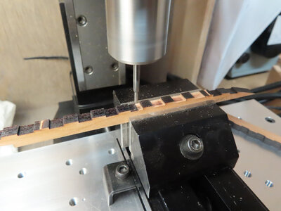
I am now gluing up BOTH sides of the Beam Support strips. In the meantime, I am prepping up the Beams. All of the NOTCHES on the beams must be either filed square or use a mill to square them. This is because the CNC Laser cutting leaves an angle. The thicker the wood, the larger the angle. Much thinner wood like 1mm the angle is near nonexistent. That is because the simple shape of the beam is triangle-shaped. All of this has been discussed in other forums.

