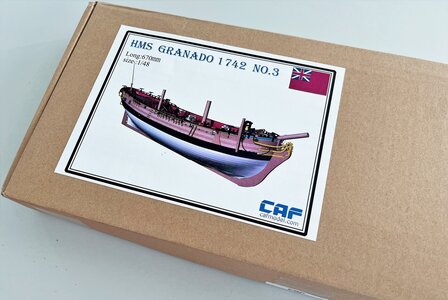
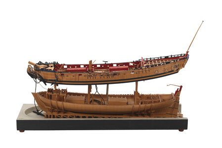
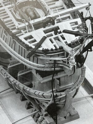
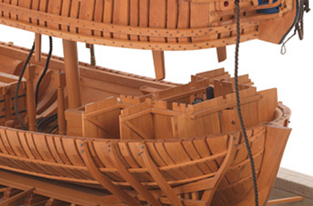
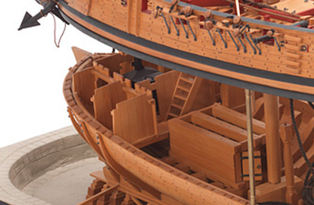
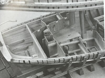
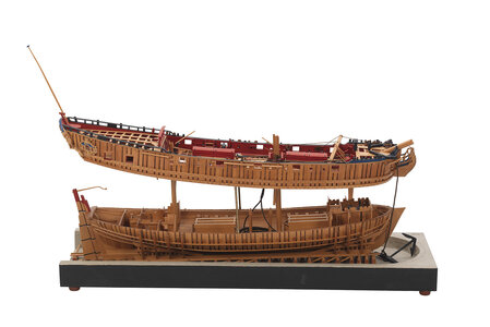
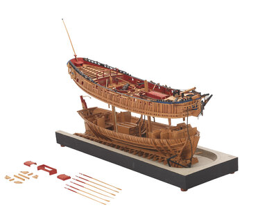
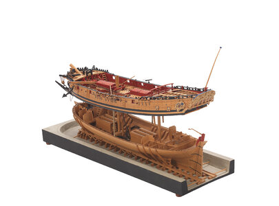
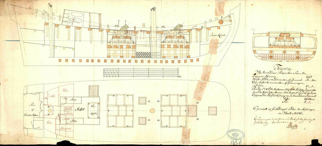
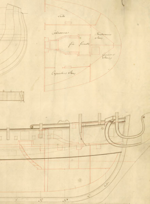
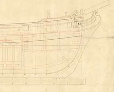
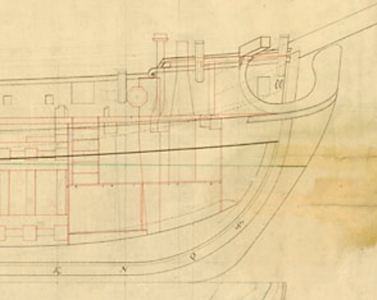
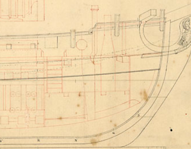
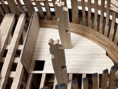
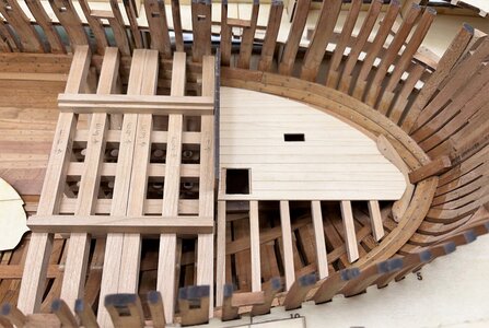
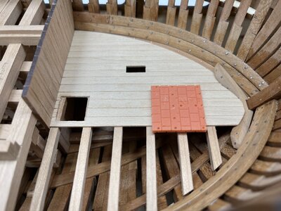
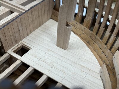
HMS GRANADO - full hull - POF kit by CAF in 1:48 - by Uwe

Hallo Don and Kurt - I agree fully, that it is often hard to remember the correct english terms.
One idea would be to start a special topic with sketches and explanation of ship elements - and off course the correct english terms.
Often POF or POB are not known......
=> a task for the future, but I think an important help for all / a lot of members
Hi Uwe, it would be great if there was a kind of library with sketches/terms for ship elements to refer to on SoS, and even more so if you could navigate from sketch to more detailed sketch including terms. But it will be a monumental task, certainly if you take into account terms changed / had an other meaning in different time periods.
I have found Patterson's Illustrated Nautical Dictionary useful (free downloadable: https://marine-cafe.com/download/pattersons-illustrated-nautical-dictionary-unabridged/ ).
Ps. Is there a dictionary for shipping terms available in different languages (English / German / French / Spanish / Italian / Dutch ..... ) ?
 
Ps. Is there a dictionary for shipping terms available in different languages (English / German / French / Spanish / Italian / Dutch ..... ) ?
a Very good one is the "Paasch", which is available also online as web-version or for download


a Very good one is the "Paasch", which is available also online as web-version or for download


Thank you so much Uwe. That will be helpful.
 
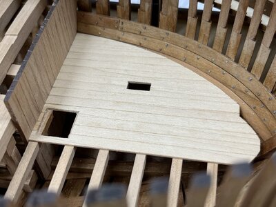
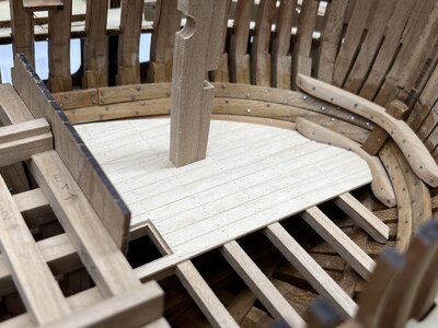
Now it is time to prepare the first platform deck of the interior of the HMS Granado

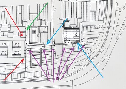
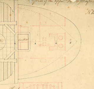
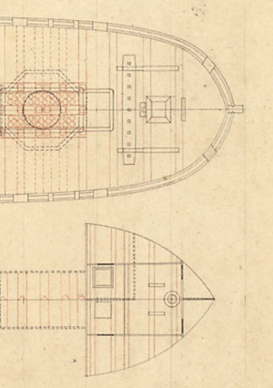
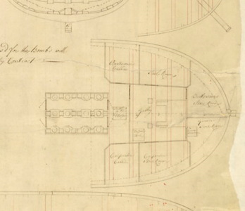
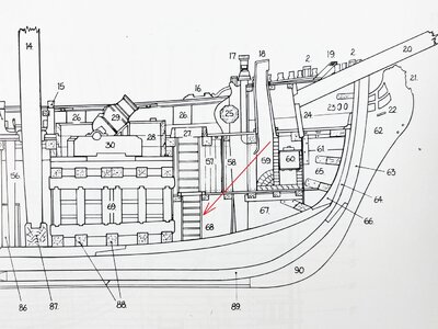
For a better orientation a view in the drawing:
Starting fore with the deck for the oven, whcih is directly in front of the mortar bed (red arrows) and divided towards the mortar bed with a small bulkhead wall (green arrow)etc. - blue is the deck, purple the beams of this deck

IMG_0658a.jpg

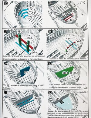
The manual is showing a very clever idea for the construction of a template (#26) , especialy for measuring and defining the correct height where the deck should be

IMG_0659.jpg

For defining the correct height I used this template, nevertheless I changed the order of construction and installed the deck planks on the deck beams outside before installation inside the hull. This decision I made latest when I realized, that my template C6-2 for the deck surface is fitting extremely good into the internal planking of the hull

But showing the working steps with photos will make it much easier for you to understand, than my stupid explanation

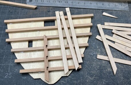
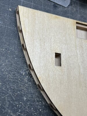
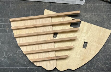
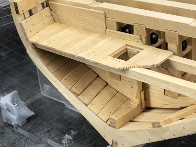
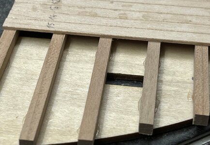
1) I glued with some spots beam strips dimension 4*4 on top of the template C6-2 following the correct location defined by the deck opening and the small longitudinal support 3A-1 (#28 of manual) - the deck planks are preshaped laser cut and have sligthly overlength (and width)
IMG_0483.jpg

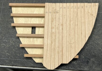
2) now the deck planking is fixed
- btw: I will partly leave the decks unplanked to get view on the construction of the decks
IMG_0484.jpg

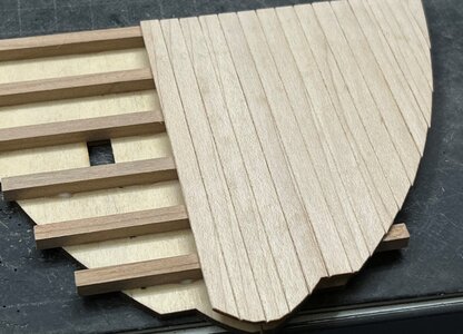
a close up
IMG_0485.jpg

IMG_0486.jpg

3) With testing the size and form of the plywood template inside the hull I knew, that it fits very good, so I was able to sand also the overlength of the beams
IMG_0520.jpg

4) with a sharp knife I removed the deck structure (beams and planks from the template - with this action I was able to cut deap into my finger, so my Granado had her ship christening with several drops of my blood

-> BE very CAREFUL every day

IMG_0521.jpg

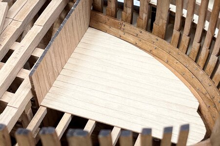
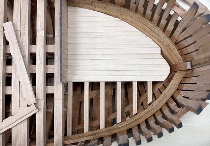
5) Dry fit
IMG_0522.jpg

IMG_0523.jpg

Many Thansk for your kind interest in my building log - :cool:
 
Hi Uwe,

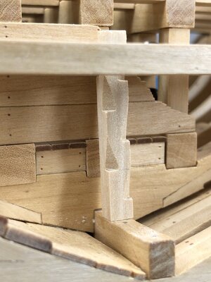
why do you use vertical timber at the bulkhead? Have a look in the build log of Giampy65. He shows the correct way how this was installed.
There is no connection between the structure under the bombs and the bulkhead, because thestructur was removable.
 
Hi Uwe,

why do you use vertical timber at the bulkhead? Have a look in the build log of Giampy65. He shows the correct way how this was installed.
There is no connection between the structure under the bombs and the bulkhead, because thestructur was removable.
Hallo Christian,
I have my doubts, that this structure of the bulkhead was removable like you describe. Or maybe better: there is for me no proof that it was removable.

But before I try to formulate arguments in this or that direction, I have to state, that my decision, of how I will make the bulkhead, especially in this are, is still open. Until now everything is still only dry fitted, so still possible to change. In moment I neede some counterwall, that the deck segment will have a basis and a limit for movement.

In principle:
1) The Granado was a bomb vessel and not like the model made by Giampy a fighting vessel. Such bomb vessels, were usually never in a direct fight with some other ships. So the risk of splintering caused by a cannon ball was extremely low, and because of this the walls were (maybe) not necessary to remove during action.
I am not aware about one biomb vessel, which was lost during an action, they were all paid off etc.
2) In principle removabel interior walls were necessary only above the waterline, but not under the waterline.
3) If removable, I can make such wall segments with vertical or with horizontal boards, so I can not see there a must for vertical or horizontal. But maybe you know a source, wehre this is defined - this would be interesting to know

Let us take a closer look to the drawings in the anatomy book of the Granado

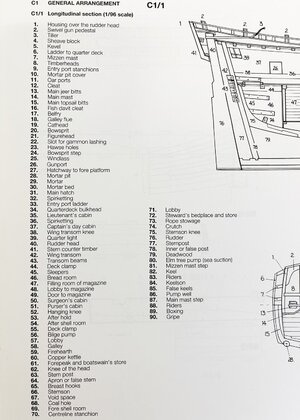
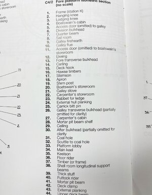
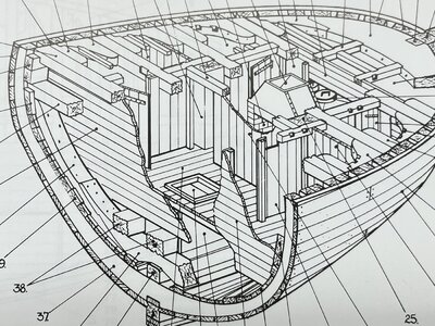
Here no wall is shown between the mortar bed and the room 68 which is the so called "coal hole" - towards 67 "void space" is also a small wall shown (void space means that this area was closed and not used in any way)
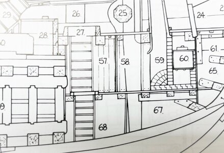
IMG_0681.jpg

IMG_0690.jpg

BTW: I have my doubts, that the entrance to the Cole hole was a ladder - in my interpretation of my section model of the Granado I made already a monkey ladder - and you recognize that here I made horizontal cladding, but no bulkhead

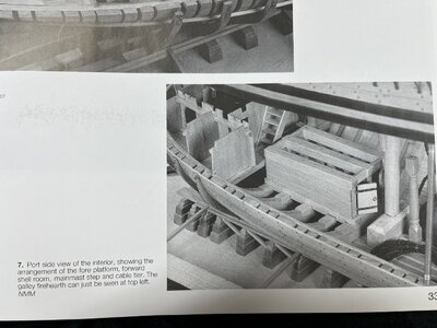
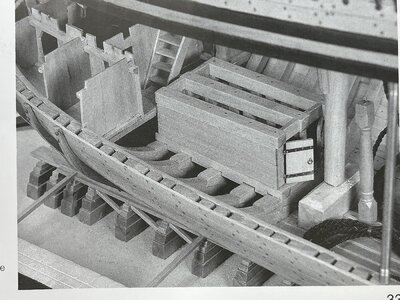
In this view Goodwin is showing a bulkhead "30" with horizontal boards, but defintely not removable, because this bulkhead is starting already in the hold.
All other walls of the different rooms are shown with horizontal boards
Remark here:
31 is showing the "cole hole" - remember this room in the hold which is connected with the deck via a ladder. Here the wall of the cole hole is directly appr. on the side of the middle lower beam of the mortar bed => if this would be correct, than the coal hole would be only 50cm wide, which can not be - so I am pretty sure, that this detail is wrong
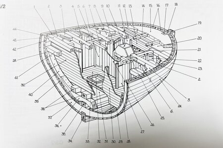
IMG_0664.jpg

IMG_0665.jpg

Here the Fore platform is shown with 17 the "After bulkhead". Visible is with the deck planking nailing, that the planks seems to end before the bulkhead, but the other walls are standing on top of the deck planking (removable or not removable).
So I interpret this, that the bulkhead is coming up from the hold up => and therefore not removable
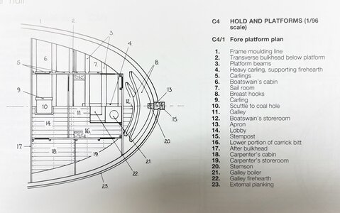
IMG_0666.jpg

Unfortunately in the book there is no top view of the hold (under the fore platform) where the walls of this cole hole should be be shown

In the following post(s) I would like to show you some more information about the research I made until now about this subject...... to be continued ....
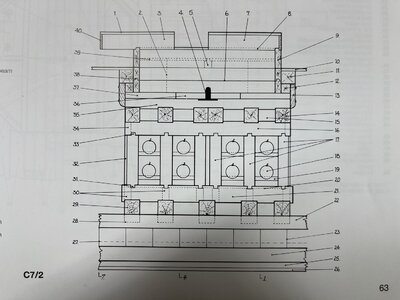
IMG_0667.jpg

IMG_0679.jpg
 
Goodwin is showing in his book also some photos of the remarkable model made by Robert Lightley in 1975

l5780_001.jpg

IMG_0673.jpg

IMG_0677.jpg

we can see, that Lightley made only a small and short wall and not a bulkhead like Goodwin is showing

Additional Remark here: The interior wall next to the visible ladder is installed much to aft - if a seaman is walking down he can not reach the area behind the ladder - so impossible that the location of this wall is correct

bute defintely the modeler made here everywhere vertical boards

IMG_0675.jpg

IMG_0676.jpg

these are excerpts from the NMM photos

Screenshot 2022-09-14 170718.png

Screenshot 2022-09-14 170837.png

also aft there are only vertical boards

IMG_0678.jpg

l5780_002.jpg l5780_003.jpg l5780_004.jpg

So there are some discrepencies between Goodwin and the model made by Lightley

..... still to be continued .....
 
I am not able (timewise) to show in moment the excerpts from contemporary drawings of this type of bom vessels - here several different information can be found, but I will try to post them tomorrow.
To all: If you have already some comments, hints or additional information about this subject, please post them here - open for discussion .....
 
Hello Uwe,

yes, Granado was from her design a bomb vessel. All models and also Goodwin are showing her in this function.

But if you follow the history in the AotS book you find that she was converted to a sloop (AO 04-07-1742) (later reconverted to a bomb vessel (AO 15-07-1745). You can find some drawings from later vessels which were used for arctic service, which are showing that the shelrooms and bomb beds were removed. After this it was also possible to use all gun ports on deck.
If you use a ship for a longer period as sloop,why do you want all special installations? It's wasting a lot of room. I am quite shure that the ship looks in the role as sloop similiar to other ketch rigged sloops.
 
I am not able (timewise) to show in moment the excerpts from contemporary drawings of this type of bom vessels - here several different information can be found, but I will try to post them tomorrow.
To all: If you have already some comments, hints or additional information about this subject, please post them here - open for discussion .....
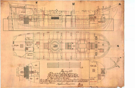
Good evening Uwek, can this drawing help?

nn.jpg
 
Good evening Uwek, can this drawing help?

View attachment 328546
Many Thanks for showing us this drawing, which is a similar principle construction of a danish bomb vessel, which were built in Nyholm by the shipbuilder Frederick Michael Krabbe.
There were 6 or 7 of this typ build and all launched in 1771.
Somehow similar, but also in several points different to the english bomb vessels like the Granado
But interesting to see and I will try to study this drawing more in detail - see. f.e. that the "bombs" were stored very aft in a store room and not under the mortars inside the mortar bed structure. also the foundation of the mortars were done by the frensh and danish with the use of several layers of cables, the english used heavy wooden layers. - mayn thanks for sharing with us

 
Hello Uwe,

yes, Granado was from her design a bomb vessel. All models and also Goodwin are showing her in this function.

But if you follow the history in the AotS book you find that she was converted to a sloop (AO 04-07-1742) (later reconverted to a bomb vessel (AO 15-07-1745). You can find some drawings from later vessels which were used for arctic service, which are showing that the shelrooms and bomb beds were removed. After this it was also possible to use all gun ports on deck.
If you use a ship for a longer period as sloop,why do you want all special installations? It's wasting a lot of room. I am quite shure that the ship looks in the role as sloop similiar to other ketch rigged sloops.
Hallo Christian,
I am building the Granado during the time as a bomb vessel, so all walls etc. should be like it could be.
Knowing that internal walls or bulkheads can be easily adjusted, removed and installed.
Even with ships like "my" Coureur, the main parts of the interiour was changed after her capture. She was before a lugger and afterwards still a lugger.

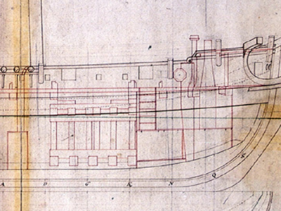
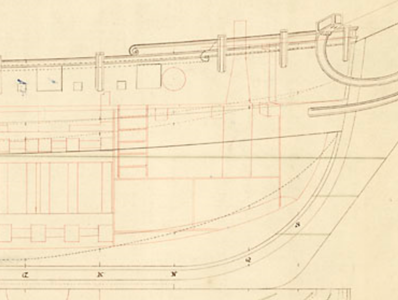
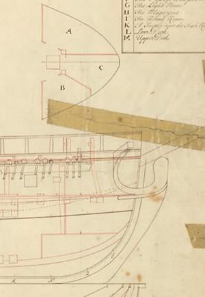
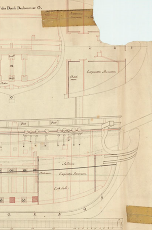
Looking once more at the contemporary drawings existing of this type of english ships, we can see a lot of different arrangements, off course also because of the converting from or to a bomb vessel.

left and right very similar
Screenshot 2022-09-19 154927.png Screenshot 2022-09-19 155151.png

already bigger differences (the right drawings shows after removing the mortar beds - see the stairs)
Screenshot 2022-09-19 155227.png Screenshot 2022-09-19 155251.png Screenshot 2022-09-19 155352.png

with wider stairs and with smaller stairs
Screenshot 2022-09-19 155412.png Screenshot 2022-09-19 155508.png

Screenshot 2022-09-19 155537.png Screenshot 2022-09-19 155557.png

Screenshot 2022-09-19 155007.png Screenshot 2022-09-19 155451.png

No need to study each single drawing, I wanted to show, that there are possibilities to very the interiour walls, fixed or removable - I try to make my interpretation of how I would make the interiour, when I woiuld be the shipwright in the yard for "a" Granado bomb vessel.
So usually I try to follow the interpretation of the manufacturer in order to use as much as possible prepared material, if the interpretation is for me not logical or needs some more details I am adjusting or changing
 
But back now to the progress on my HMS Granado with the fore platform

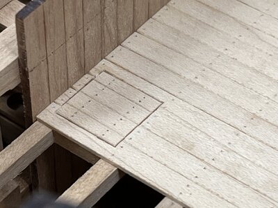
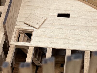
next step was opening the hatch and the necessary opening for the ......

IMG_0524.jpg

for this elements for the windlass - they are located exactly between two of the beams

IMG_0525.jpg

IMG_0527.jpg

upps - I forgot that there is also the place of the firehearth - I have to check

IMG_0528.jpg

not good - the base of the firehearth is showing, that the planking is not enough - so I have to add one or two planks more - I have to make this in a later state

now the imitation of the plank nailing

IMG_0538.jpg

IMG_0539.jpg

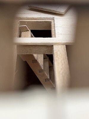
Goodwin is showing here no cover, but an open hatch town to the coal hole - I do not think that this was done in such a way - my interpretation is a small cover (the ringbolts are still missing)

IMG_0541.jpg

and off course the ladder is missing (content of the kit) - maybe I change it to a monkey ladder like in my section - especialy when I make the coal hole relatively small - a ladder would need to much space, which could be not used for coal storage

but a nice detail
IMG_0542.jpg

IMG_0543.jpg

Many Thanks for your interest ..... to be continued ....
 
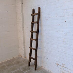
Lovely work. Do you think there was this big ladder to this small compartment? I think like in the program of Ab Hoving of the virtual tour in the Pinas and the Fluyt that there is a pole with sticks on either side to hold onto and step on. Or something similar. You almost couldn't stand straight up in that compartment down there.
something like this
ladder old.JPG
 
Lovely work. Do you think there was this big ladder to this small compartment? I think like in the program of Ab Hoving of the virtual tour in the Pinas and the Fluyt that there is a pole with sticks on either side to hold onto and step on. Or something similar. You almost couldn't stand straight up in that compartment down there.

something like this
View attachment 329325
I think more like such one I made in the Granado section

IMG-8829.jpg

IMG-8834.jpg

The coal was stored there in the hold, coal was only necessary for the firehearth and maybe the oven for the captain.
So I guess the helper of such a ship´s cook was a young boy, who was send 3 or 4 times a day down into the coal room to bring 2 o3 buckets of coal up.
A bucket fixed to a rope, the boy young, small and full of energy can climb down, fill the bucket, climb up and lift the bucket up with the rope.
I think storage space was more important than the convinience of a 14 years old no-name boy.
This is somehow my naiv interpretation.

but also in all contemporary drawings no real stairway was shown from the coal room up - only Goodwin shows it

IMG_0591a.jpg
 
I think more like such one I made in the Granado section

IMG-8829.jpg
yes that's exactly you see in the Dutch ships. When they could climbed in the shrouds, such a pole will be a "makkie". Dutch for a very easy job to do, mostly used by old soccer players in our country, like Sjaak Swart.
 
Back
Top