- Joined
- Oct 23, 2018
- Messages
- 886
- Points
- 403

I would follow your interpretation for the ladder, Uwe
 |
As a way to introduce our brass coins to the community, we will raffle off a free coin during the month of August. Follow link ABOVE for instructions for entering. |
 |
 |
The beloved Ships in Scale Magazine is back and charting a new course for 2026! Discover new skills, new techniques, and new inspirations in every issue. NOTE THAT OUR FIRST ISSUE WILL BE JAN/FEB 2026 |
 |

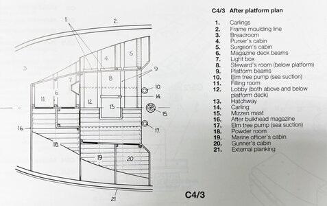
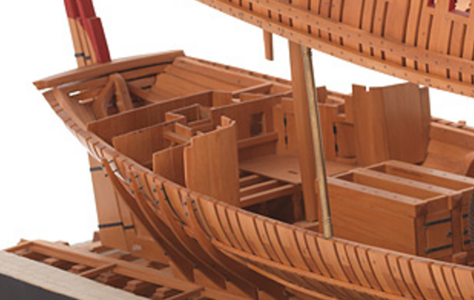
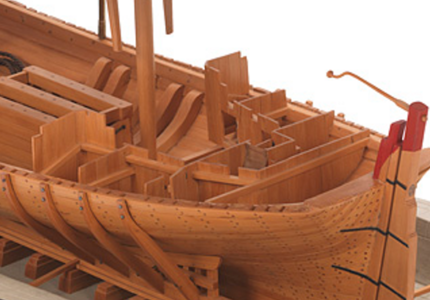
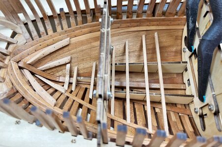

Sorry Uwe, are these two details removed?Due to the fact, that I still do not decide what and how I will do the fore platform,
I moved to the aft platform - maybe here the decision process is easier
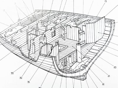
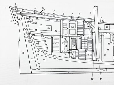
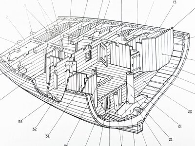
These are the related drawings and sketches shown in Goodwins Anatomy book
View attachment 330160
View attachment 330159 View attachment 330161
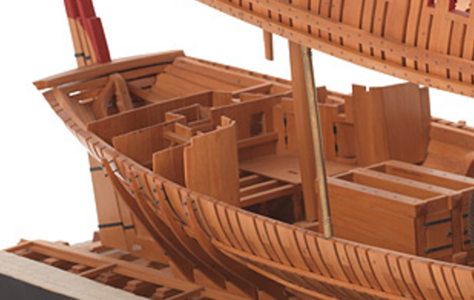
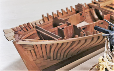
We have also some close up photos of the already mentioned superb model
View attachment 330162
View attachment 330163
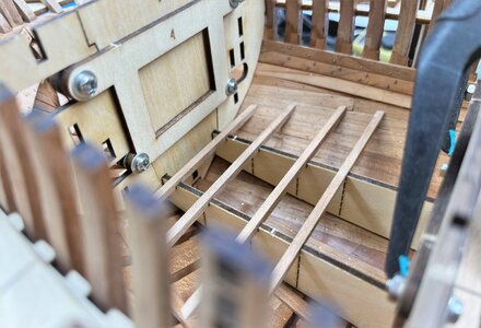
CAF prepared some templates which have to be fixed in correct slots of the temporary bukhead templates which were already used in the past for the correct height of the clamps - so multi-use of them
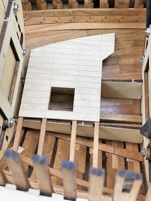
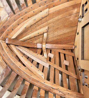
Here you can see the small beams for the platform laying on the two templates - with this you can easily define the correct location in longitudinal direction (fore - aft) and also the correct height
View attachment 330164
View attachment 330165
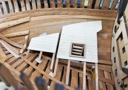
Here you can see one of the platforms already fixed on the beams
View attachment 330166
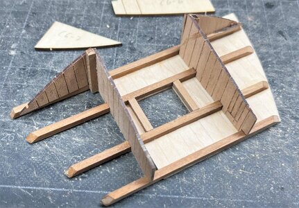
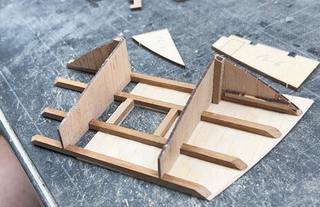
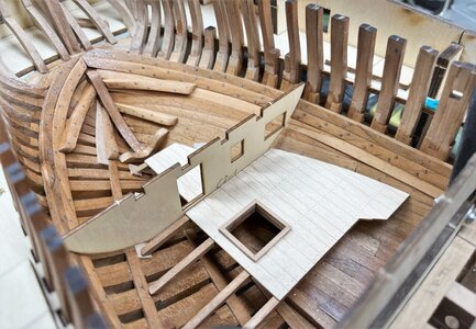
under the platform in the hold are two small storage rooms - later on the platform with the attached walls have to be turned upside down
View attachment 330167
View attachment 330168
I wish you all a nice weekend .... and many thanks for the interest in my building log ..... to be continued .....
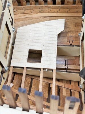
Yes - these are some temporary plywood templates to define the correct height of the platform

Thanks for answering meYes - these are some temporary plywood templates to define the correct height of the platform
Beautiful work Uwe,Hallo friends,
first of all many thanks to all comments and all the likes received - much appreciated
Some smaller progress to show
One sleeper was partly hanging in the air, so I added one small part of an additional inner plank with treenailing (lighter wood) and also some smaller "plank-segments" where later on the beams of the platform are founded - in my opinion it is looking better or technical more correct
View attachment 330720
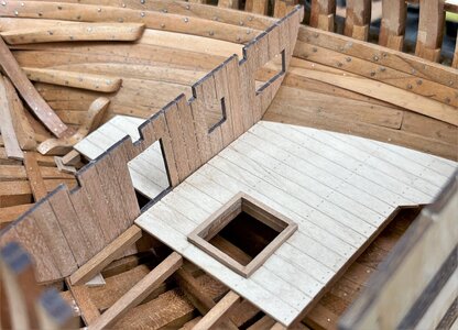
the two small platforms - here a ladder was also prepared
View attachment 330721
here with a template for the bulkhead wall in order to check or adjust the form
View attachment 330722
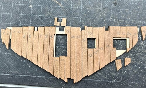
this bulkhead template is used to prepare the final wall with the single boards
View attachment 330723
the final result
View attachment 330724
Many Thanks for the interest in my work .... to be continued .....
Good morning Uwek. Your build is on another level- I don’t think I would ever get there. I have huge admiration for you guys who build like this. Cheers Granta next small step with two bigger steps
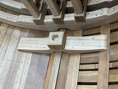
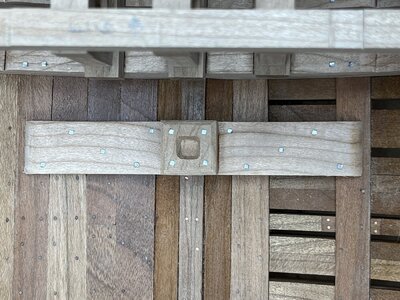
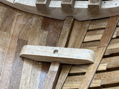
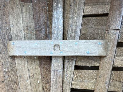
The mast steps were prepared and "bolted" (according the pattern shown in Goodwins book)
View attachment 330989
View attachment 330992
the second one - still dry fitted, the correct location will be defined later on
View attachment 330990
View attachment 330991
In the meantime I installed also the 3mm thick main clamps for the deck beams - unfortunately I forgot to make some photos, but partly it was already shown in earlier posts.
These clamps received also the square bolts
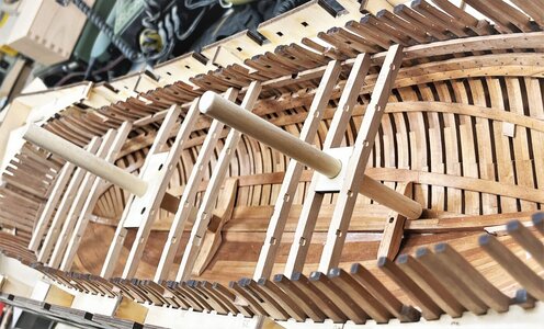
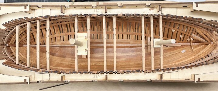
with the final installed clamps I had the chance to dryfit the main deck beams and made a first test with the mast-stumps
btw: the wooden elements with the mast holes, installed between two beams are once more templates included in the kit - with them, an angle of 2° of the mast, the correct location of the mast-steps will be defined
View attachment 330993
View attachment 330994
Many Thanks for your interest .... to be continued .....
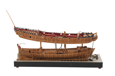
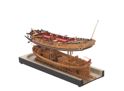
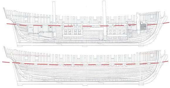
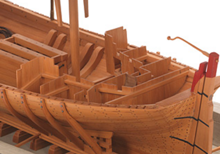

Good afternoon Uwe, I ask, the Baglietto estate is not on the Baglio, why? I think that makesSo let us concentrate first on the aft area
View attachment 331372
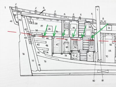
These are the sketches from Goodwin, marked in red with the appr. planned cutting line
View attachment 331371
We can see, that the after cabin deck will be part of the upper ships segment (the deck marked with "21" in the first sketch above, so also the six small deck beams marked with green arrows have to be part of the upper segment
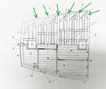
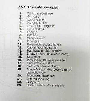
The skecth from Goodwin showing the after cabin deck plan and also the six beams
View attachment 331374
View attachment 331375
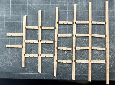
so the next step will be the praparation of this after cabin deck structure with beams, carlings and laying knees.
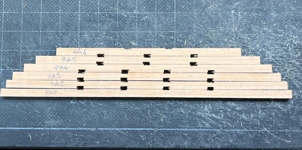
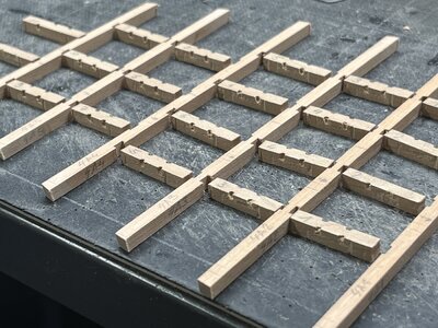
The following photo is showing the six beams with the prepared notches for the carlings
View attachment 331373
Ready for finetuning ....
View attachment 331376
View attachment 331377
to be continued ..... and btw many thanks for your interest in my build
A bold decision to cut your ship. I know you determined to do this from the beginning but reality is not always actualized along with the dream. I wish you success Uwe!So let us concentrate first on the aft area
View attachment 331372
These are the sketches from Goodwin, marked in red with the appr. planned cutting line
View attachment 331371
We can see, that the after cabin deck will be part of the upper ships segment (the deck marked with "21" in the first sketch above, so also the six small deck beams marked with green arrows have to be part of the upper segment
The skecth from Goodwin showing the after cabin deck plan and also the six beams
View attachment 331374
View attachment 331375
so the next step will be the praparation of this after cabin deck structure with beams, carlings and laying knees.
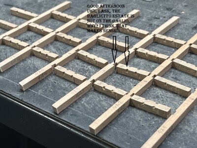
The following photo is showing the six beams with the prepared notches for the carlings
View attachment 331373
Ready for finetuning ....
View attachment 331376
View attachment 331377
to be continued ..... and btw many thanks for your interest in my build
