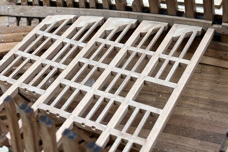
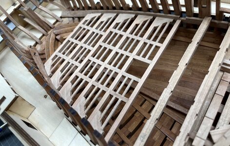
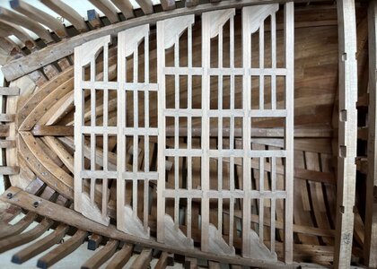
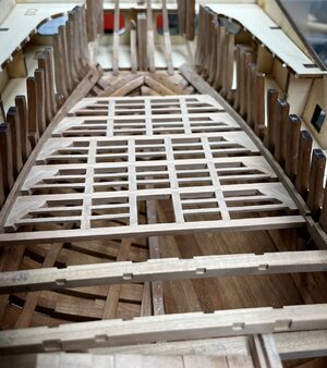
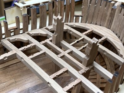
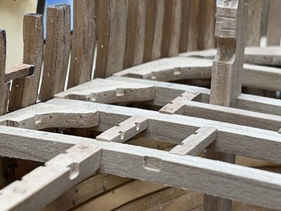
HMS GRANADO - full hull - POF kit by CAF in 1:48 - by Uwe

I did not understand the discussion fully.

The CAF model and also Uwe are showing the typical English method of the deck frameing beams, carlings and ledges. The AOTS also shows beamarms. and I think that Uwe will also do by the next deck (In the original drawings I don't find a hint but it is always a question if they were omitted because this detail was standard practice).
The model has in the construction a simplification. The carlings and the beams have the same thickness which was not common practice. On the finished model this is not really visible by the platform.
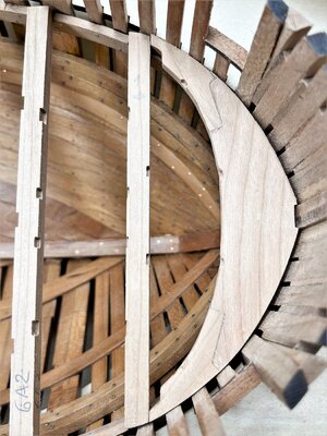
Hello, I think with this image the various doubts we have are completely resolved

za2.jpg
 
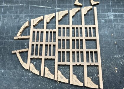
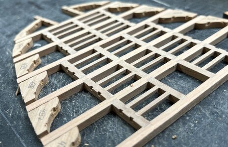
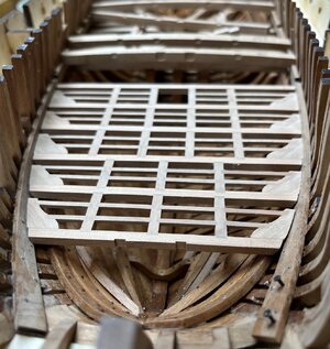
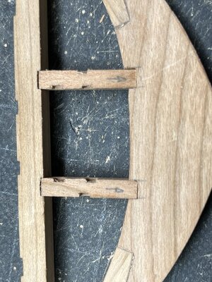
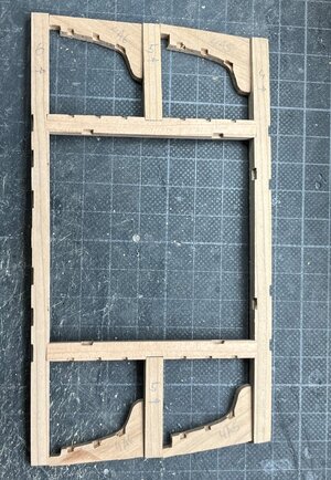
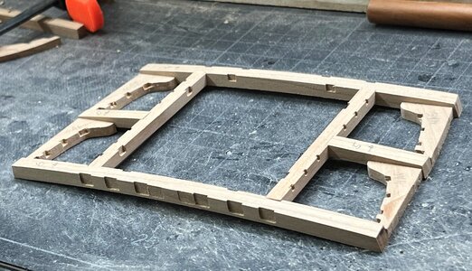
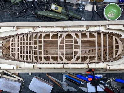
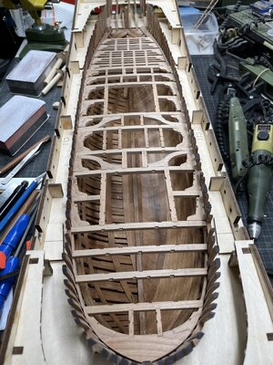
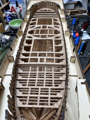
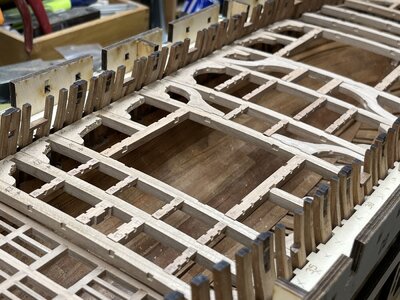
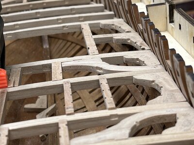
The next working step - installation of the carlings with 2*2mm stripes

View attachment 332348

View attachment 332349

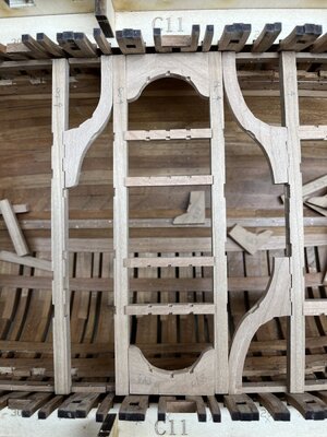
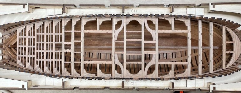
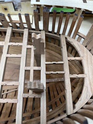
and the dry fit inside the hull

View attachment 332350

View attachment 332351

step by step - Laboriously the squirrel lives
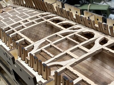
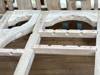
The next are the laying knees and the carlings attached to the knees

Many Thanks for your interest .... to be continued
Inbetween the discussion: a very nice and precise piece of deck construction, Uwe. Afterall we (almost) can’t see what kind of fitting is made. But that’s for more builds: we know!
Regards, Peter
 
Inbetween the discussion: a very nice and precise piece of deck construction, Uwe. Afterall we (almost) can’t see what kind of fitting is made. But that’s for more builds: we know!
Regards, Peter
Hi Pietro, I have never allowed myself to criticize Uwek's work for the beautiful work he is doing but, I notice that my observations are annoying, I close here any comments in the Forum, I limit myself only to observing, greetings
 
In order now to clarify one final information about the kit.

This is realy a simplification like Christian mentioned in his post, and was prepared by CAF only in the lower deck area aft (red line),
which will be once more covered by a next deck.
So usually absolutely not visible from the top.

IMG_0646ab.jpg

The normal deck beams (green marked area) are different
IMG_1245.jpg

But stay tuned ......
 
In order to come back to the building log, I would like to show further photos of this mentioned after cabin deck structure

with lodging / laying knees

IMG_0743.jpg

IMG_0744.jpg

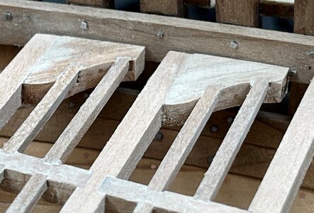
some closer look of the knees with copper "bolting" and carlings and ledges

IMG_0748.jpg

one side prepared (the deck structure is still only dry fitted in the hull)

IMG_0749.jpg

IMG_0751.jpg

Many Thanks for your interest in my building log, many thanks for the discussion and comments ..... to be continued ....
 
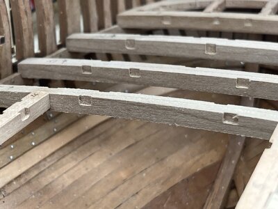
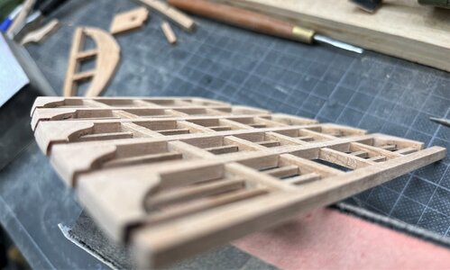
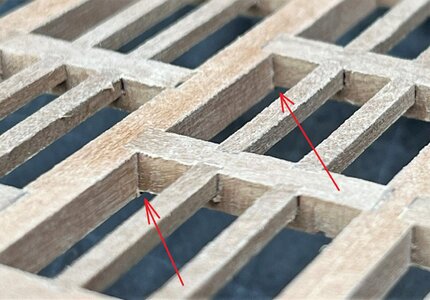
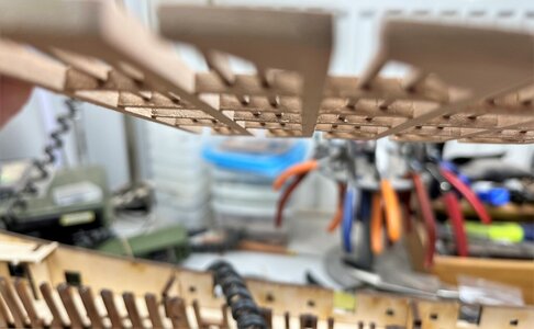
and now I can show you also the final solution I prepared to solve the "problem" with the carlings have / had the same height like the small beams of this deck

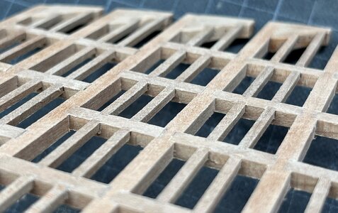
The following is howing the deck structure bottom side - I have sanded the carlings down by 0,5 to 1mm. just so much, that there is a small height difference at the connecting to the beams - but nobody will see the model from this side

IMG_1117.jpg

usually it would be this perspective view from the top down

IMG_1119.jpg

- if you look close you can see barely this small step - finaly this view has to be through the main deck structure, so also not really visible

IMG_1119a.jpg

But as you know, I plan to cut the hull on the waterline and present the upper part of the ship somehow floatinmg over the hull in app. 20cm -> so also this viw could be possible, if someone will go on his knees and look upwards

somehow like this view

IMG_1116.jpg

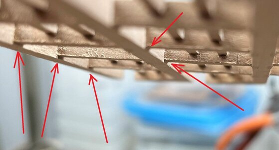
even then some small shadows will show, that the carlings are "laying in recesses in the beams

IMG_1116a.jpg

Easy solution with finaly acceptable result (in my opinion)

Many Thanks for your interest .... to be continued .....
 
and now I can show you also the final solution I prepared to solve the "problem" with the carlings have / had the same height like the small beams of this deck

The following is howing the deck structure bottom side - I have sanded the carlings down by 0,5 to 1mm. just so much, that there is a small height difference at the connecting to the beams - but nobody will see the model from this side

View attachment 333953

usually it would be this perspective view from the top down

View attachment 333954

- if you look close you can see barely this small step - finaly this view has to be through the main deck structure, so also not really visible

View attachment 333956

But as you know, I plan to cut the hull on the waterline and present the upper part of the ship somehow floatinmg over the hull in app. 20cm -> so also this viw could be possible, if someone will go on his knees and look upwards

somehow like this view

View attachment 333952

even then some small shadows will show, that the carlings are "laying in recesses in the beams

View attachment 333955

Easy solution with finaly acceptable result (in my opinion)

Many Thanks for your interest .... to be continued .....
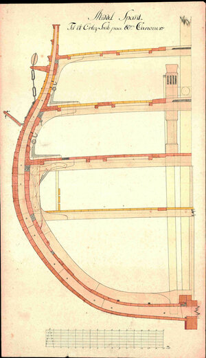
Dear Uwek
sophisticated solution Exclamation-MarkOkay:)
looks great from the top
 
and now I can show you also the final solution I prepared to solve the "problem" with the carlings have / had the same height like the small beams of this deck

The following is howing the deck structure bottom side - I have sanded the carlings down by 0,5 to 1mm. just so much, that there is a small height difference at the connecting to the beams - but nobody will see the model from this side

View attachment 333953

usually it would be this perspective view from the top down

View attachment 333954

- if you look close you can see barely this small step - finaly this view has to be through the main deck structure, so also not really visible

View attachment 333956

But as you know, I plan to cut the hull on the waterline and present the upper part of the ship somehow floatinmg over the hull in app. 20cm -> so also this viw could be possible, if someone will go on his knees and look upwards

somehow like this view

View attachment 333952

even then some small shadows will show, that the carlings are "laying in recesses in the beams

View attachment 333955

Easy solution with finaly acceptable result (in my opinion)

Many Thanks for your interest .... to be continued .....
Lovely work Uwe,

Cheers,
Stephen.
 
Nice solution, Uwe.
Is it correct, that you will install the ensemble later under the planks in the space area?
Correct
But I think, that I will install and fix it before I will cut horizontal - it will help additional for the stabilizing of the upper "space area"

and btw to all who made kind comments - many thanks
and also for all the likes received -> much appreciated

The next to be prepared are the real deck beams, carlings, lodginging knees etc.

So I removed all the temporary internal stuff like the mortar beds etc. and concentrated of this deck structure

so first some impression about the elements - everything only dry fitted

at the bow

IMG_1109.jpg

IMG_1115.jpg

one frame for the mortar

IMG_1143.jpg

IMG_1144.jpg

the midship section with the heavy lodging knees

IMG_1220.jpg

IMG_1221.jpg

as mentioned - in moment only some impressions .... to be continued .....
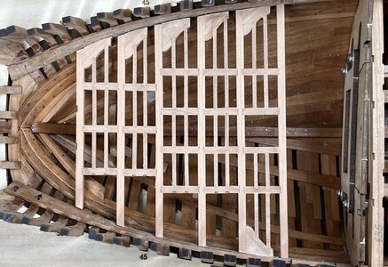
and mayn thanks for your interest :cool:
 
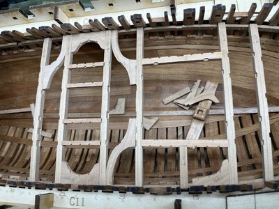
step by step - still everything dry fitted and not glued - aim is that all element are getting the more or less correct fit

IMG_1226a.jpg

btw this is the original photo showing the obligatory and usual mess on my table
IMG_1226.jpg

IMG_1227.jpg

IMG_1228.jpg

the recess on the lodging knees are still not prepared - important is here a parallel orientation of the carlings and ledges

IMG_1229.jpg

all carlings are prepared

IMG_1230.jpg

some of the carlings are still too high, so the recesses have to be overworked

IMG_1232.jpg

the recesses for the ledges have to be prepared by fine chisels (see on the left one reccess in original round shape caused by the normal cnc machine - a time consuming work

IMG_1243.jpg

IMG_1255.jpg

IMG_1256.jpg

IMG_1257.jpg

still a lot of work in front of me ..... many thanks for your interest
 
Back
Top