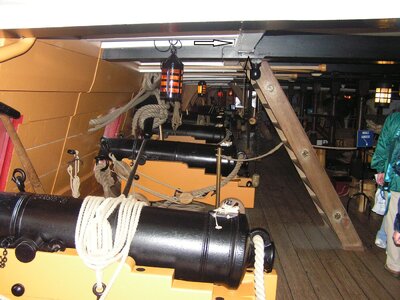
HMS GRANADO - full hull - POF kit by CAF in 1:48 - by Uwe

Step by step it is getting closer to the decision how, when and where I have to cut my ships hull horizontal to get the two segments

As you know I plan to present my model somehow similar like the Leighton model

View attachment 331361

View attachment 331362

I am still on the beginning of this Brainstorming - in moment it is still a storm in my brain

So the first decision will be "WHERE" can I make the cut, including the definition, which parts will be installed at the lower part and which elements will be fixed to the upper part of the ships model

First the appr. line for the cut on the CAF-drawing

The cut will be slightly under the clamps of the main deck but over the clamps for the mortar bed beams

View attachment 331370

This height is also confirmed by the the photos of the model

View attachment 331368

Here we can see that the leighton model is partly simplified close to the stern

View attachment 331367

The model Tom from CAF was showing (I do not know, who is the modeler of this one) has the devision also in this height.

View attachment 331369
I love this post, Uwe. Another cut of a model!
From now on it will definitely be running through your mind: When ....... When .... When.... Until you give in. :)
Regards, Peter
 
Great work Uwe. IMHO you really need to follow the approach of the Leighton model and have the cut flush with the base of the lower wale.The other option is far less aesthetically pleasing.

This really will require clever thought as the design of the ship doesn't easily lend itself to it.

Kind Regards

Nigel
 
Hi Uwe, a trip back into memory lane.
I think you have to look at the flow of the lower wale compared to the fow of the deck clamp.
As Nigel mentioned I agree that cutting below the wale is most pleasing but then you have to be care not to saw through the deck clamps suppporting your deck beams.
I had to cut in the bow slightly below the wale for this reason.
Post in thread 'Hms Alert by Maarten' https://shipsofscale.com/sosforums/threads/hms-alert-by-maarten.6097/post-154943
 
Maarten mentions something that had also crossed my mind.Wonder if somehow the deck, beams and clamps can be built into the upper section to slot into the lower or stand proud in the lower section but still maintain a full wale on the upper??

Just throwing some ideas out there......

Kind Regards

Nigel
 
Hello Uwe wonderful work, I have to catch up on the last few days of your report, the progress was no longer displayed to me. Your intention to make a longitudinal section as shown in the pictures above is a house number. I already admired this when @Maarten built the Alert. I agree with Nigel ( @NMBROOK ) that it is very difficult to keep the aesthetic of the torso, I hope you already have a plan and I wish you the best of luck. I am very excited.
 
First of all - many many thanks to everybody particpating in the brainstorming procedure, giving hints and tips and advise
Much appreciated
I hope, that during the next weekend I will have the chance to play a little bit and come closer to decisions related to the hull cutting

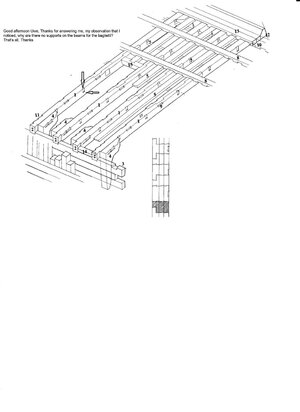
Good afternoon Uwe, I ask, the Baglietto estate is not on the Baglio, why? I think that makes
Sorry Frank, but I do not understand your question, but maybe with the next progress photos it is answered or clarified
 
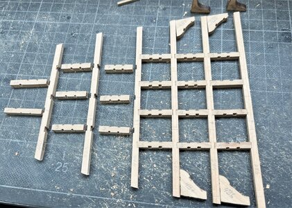
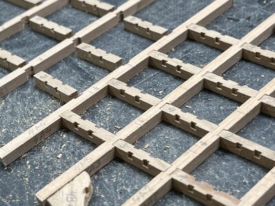
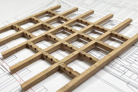
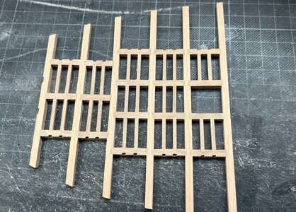
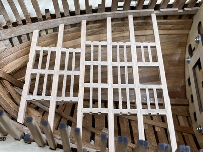
In the photos of my post #337 the notches of the carlings were not prepared - important at the end is the alignment, so that the carlings are as parallel as possible

on the right 4 beams and carlings prepared, the left still not
IMG_0734.jpg

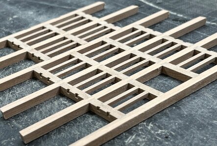
the notches are 2*2mm

IMG_0735.jpg

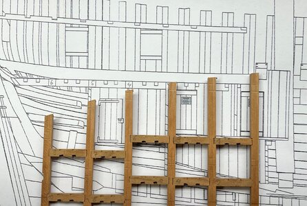
finaly the distances of the 6 beams have to be adjusted - important also here: the notches have to be in one line, so that there are rectangle angles and parallel

IMG_0736.jpg

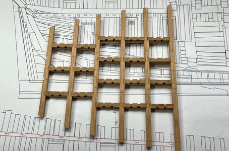
everything prepared for final fixing with glue

IMG_0737.jpg

IMG_0738.jpg

Many Thanks for your interest .... to be continued ......
 
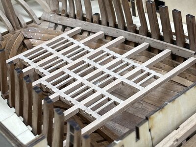
The next working step - installation of the carlings with 2*2mm stripes

IMG_0739.jpg

IMG_0740.jpg

and the dry fit inside the hull

IMG_0741.jpg

IMG_0742.jpg

step by step - Laboriously the squirrel lives
The next are the laying knees and the carlings attached to the knees

Many Thanks for your interest .... to be continued
 
First of all - many many thanks to everybody particpating in the brainstorming procedure, giving hints and tips and advise
Much appreciated
I hope, that during the next weekend I will have the chance to play a little bit and come closer to decisions related to the hull cutting


Sorry Frank, but I do not understand your question, but maybe with the next progress photos it is answered or clarified
Good afternoon Uwe, that's what I meant.

sos.jpg
 
Hi Frank

The drawing you show is of French deck construction which is very different to English construction

Kind Regards

Nigel
Good evening Nigel, I'm sorry to contradict you, it's not a question of French or English carpentry, see the English one well, I'm documented. It is not the first time, I hope I'm wrong I have the impression that my observations bother, if so I can safely go out there is no problem
 
Many Thanks for the interest in the build and also your comments and replies - also off course for all the likes received.

@Frank48
Many thanks for your comment and question.
As Nigel mentioned correctly, your sketch is french and my ship is english, but some structural technical needs have to be fullfilled in both navies and also their shipyards.

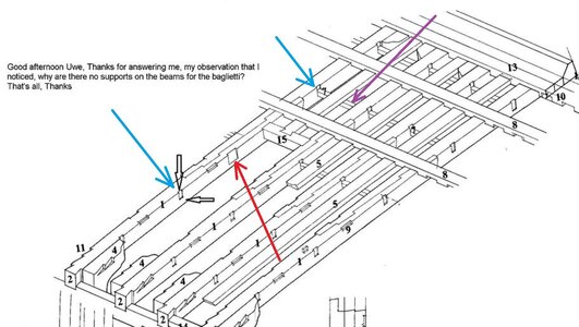
Taking your sketch you marked maybe not the best example for such a notch (connection beam to carling)
The correct notch / recess under question would be the red arrow
The blue arrow notches / recesses are in french shipbuilding rectangle holes trough the beam in which rectangle smaller ledges (purple arrow) are installed - they are longer slats going through several beams
sosa.jpg

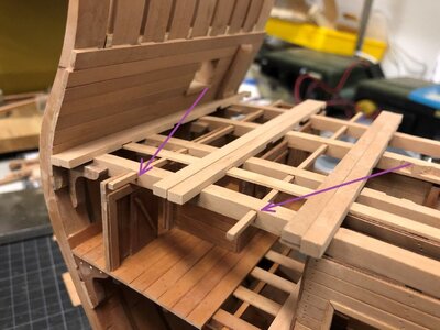
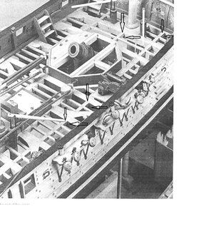
For better understanding, also for other interested members, here a photo of my Bonhomme Richard section

3.jpg

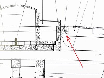
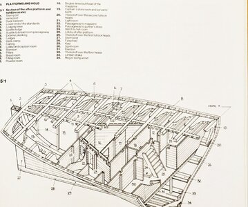
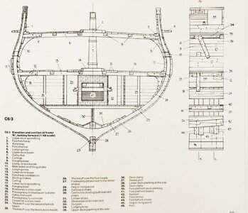
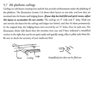
In the Anatomy book about the Granado written by Goodwin, there are several indications but no clear information about the height of the carlings, which are under question

Here we can interprete, that the height of the carlings is smaller than the beam
IMG_1123a.jpg

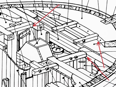
Here also, but it is not a typical carling, it is also a heavier beam fixing the mortar bed construction

IMG_1126a.jpg

Here also at the partners for the pumps

IMG_1127a.jpg

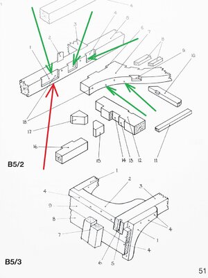
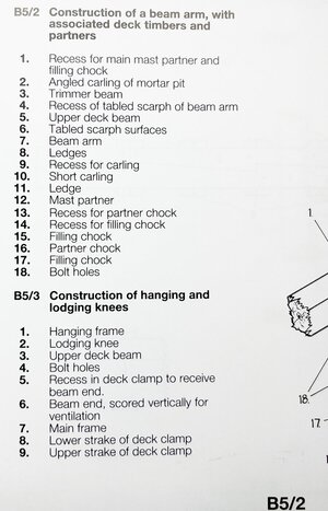
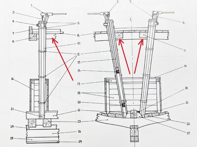
Interesting also this detail showing the structure of the mast partners
with red arrow the notch / recesses for such a stronger carling (#12 mast partner)
with #3 we can see the "Trimmer beam" which could be one of the carlings
Very interesting to see and marked with green arrows are the bolt holes with which the knee, beam and carlings are in addition fixed
So these carlings were not only layed into some recesses, but also fixed with horizontal bolts
IMG_1120a.jpg
IMG_1121.jpg

In this Anatomy book you can not find more information about carlings, their height and form of recesses

When we take a look at the Anatomy book of the Blandford we can find these 3D sketch and the cross section, showing clearly, that the carlings have a smaller height than the beams, which would confirm your point.

IMG_19371.jpg

IMG_19381.jpg

I studied these information before startiung with my work on the structure and in short time I will be able to show you my interpretation and also how I executed this detail finally.

Many Thansk for your interest - I hope these info were not to boring .....
 
Many Thanks for the interest in the build and also your comments and replies - also off course for all the likes received.

@Frank48
Many thanks for your comment and question.
As Nigel mentioned correctly, your sketch is french and my ship is english, but some structural technical needs have to be fullfilled in both navies and also their shipyards.

Taking your sketch you marked maybe not the best example for such a notch (connection beam to carling)
The correct notch / recess under question would be the red arrow
The blue arrow notches / recesses are in french shipbuilding rectangle holes trough the beam in which rectangle smaller ledges (purple arrow) are installed - they are longer slats going through several beams
View attachment 332540

For better understanding, also for other interested members, here a photo of my Bonhomme Richard section

View attachment 332532

In the Anatomy book about the Granado written by Goodwin, there are several indications but no clear information about the height of the carlings, which are under question

Here we can interprete, that the height of the carlings is smaller than the beam
View attachment 332535

Here also, but it is not a typical carling, it is also a heavier beam fixing the mortar bed construction

View attachment 332536

Here also at the partners for the pumps

View attachment 332537

Interesting also this detail showing the structure of the mast partners
with red arrow the notch / recesses for such a stronger carling (#12 mast partner)
with #3 we can see the "Trimmer beam" which could be one of the carlings
Very interesting to see and marked with green arrows are the bolt holes with which the knee, beam and carlings are in addition fixed
So these carlings were not only layed into some recesses, but also fixed with horizontal bolts
View attachment 332533
View attachment 332534

In this Anatomy book you can not find more information about carlings, their height and form of recesses

When we take a look at the Anatomy book of the Blandford we can find these 3D sketch and the cross section, showing clearly, that the carlings have a smaller height than the beams, which would confirm your point.

View attachment 332538

View attachment 332539

I studied these information before startiung with my work on the structure and in short time I will be able to show you my interpretation and also how I executed this detail finally.

Many Thansk for your interest - I hope these info were not to boring .....
Hi Uwek, what you post is not boring at all, indeed I thank you for your answers and respect but, I am of my opinion as expressed. I know well that it is French shipbuilding, there is no need for Nigel to say it

770957177_600d410ee5_o.jpg

9461299422_1f534b0e91_o.jpg

III ponte.jpg

baglio buono1.jpg

baglio buono.jpg
 
Sorry Uwe @Uwek if I'm interrupting your construction report on the subject of constructions. I am a bit confused, could it be the translation program, I have the impression that we are talking past each other? I am very interested in the subject, especially the difference between English and French constructions. Do we have an area somewhere where we can discuss this?

Übersetzt mit DeepL (https://www.deepl.com/app/?utm_source=ios&utm_medium=app&utm_campaign=share-translation
 
I did not understand the discussion fully.

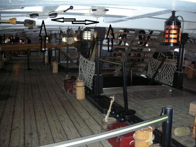
The CAF model and also Uwe are showing the typical English method of the deck frameing beams, carlings and ledges. The AOTS also shows beamarms. and I think that Uwe will also do by the next deck (In the original drawings I don't find a hint but it is always a question if they were omitted because this detail was standard practice).
The model has in the construction a simplification. The carlings and the beams have the same thickness which was not common practice. On the finished model this is not really visible by the platform.
 
Back
Top