Amazingly good work on what must be a most demanding task.
-

Win a Free Custom Engraved Brass Coin!!!
As a way to introduce our brass coins to the community, we will raffle off a free coin during the month of August. Follow link ABOVE for instructions for entering.
-

PRE-ORDER SHIPS IN SCALE TODAY!
The beloved Ships in Scale Magazine is back and charting a new course for 2026!
Discover new skills, new techniques, and new inspirations in every issue.
NOTE THAT OUR FIRST ISSUE WILL BE JAN/FEB 2026
You are using an out of date browser. It may not display this or other websites correctly.
You should upgrade or use an alternative browser.
You should upgrade or use an alternative browser.
HMS GRANADO - full hull - POF kit by CAF in 1:48 - by Uwe
Hallo @Maarten,These are serious deck clamps Uwe. That must have cost a lot of steam and heat.
no steam - only watering some 10 minutes in warm to hot water - afterwards the plank is already much more flexibel. and finally with the Kolderstock bending iron with the smaller dip (in the middle of the photo). After checking the bend directly at the hull, maybe one or two more corrections (water and iron) it was working to be acceptable

The second row of clamps were bended, afterwards installation of the same square bolts with similar pattern like the installed one
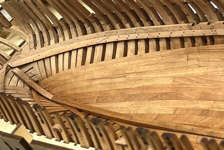
I am by myself not 100% happy with the result - but at the end these clamps will be only partly visible - nobody will be able to have a view along the edges of these clamps -> so the result is acceptable
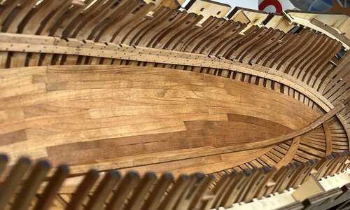
dryfitting of the riders
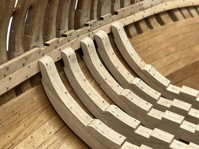
Many Thanks for your interest .... to be continued .....

I am by myself not 100% happy with the result - but at the end these clamps will be only partly visible - nobody will be able to have a view along the edges of these clamps -> so the result is acceptable

dryfitting of the riders

Many Thanks for your interest .... to be continued .....
Very nice Uwe, once again! Do you ever sleep?
I'm at the same stage at present, but without the internal planking. The bending of the beam clamps is extreme, particularly at the bows, but coming on nicely with plenty of steam and clamping! It can be done!
Ted
I'm at the same stage at present, but without the internal planking. The bending of the beam clamps is extreme, particularly at the bows, but coming on nicely with plenty of steam and clamping! It can be done!
Ted
Hallo Ted,
I agree, Yes - it can be done....
not easy, but with the good quality timber and some patience it is possible to get an acceptable result.
I mentioned already the thrid clamp plank. In the kit you can find the plank "D" for the adjustments between the clamps and the inner planking
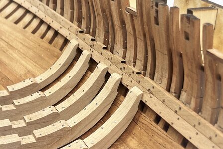
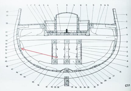
Looking at the cross section in the Anatomy book from Goodwin we can find the plank "51" marked with the red arrow as a thick stuff upper strake planking
so I decided to use the kit plank "D" and used the form as a template for a scratch plank of bigger thickness, so I prepared a 2,2mm thick sheet (with my small turkish thicknesser from Netmak) and praped this plank
starting point is the midship
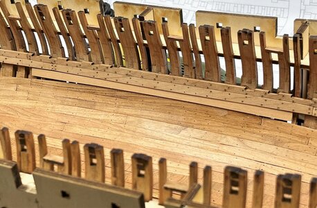
also the bow - I used here copper nails as bolting in order to get a more visible difference to the clamps
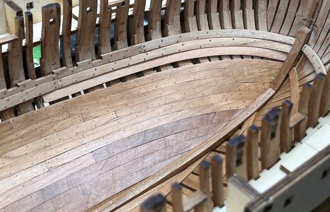
and finally also the plank direction towards the stern
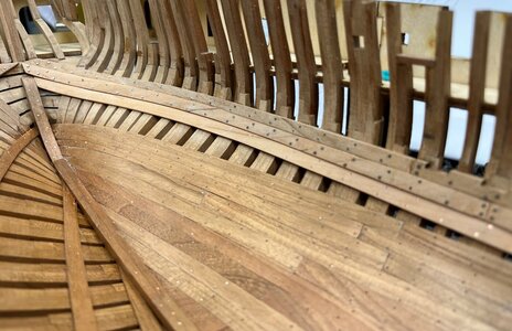
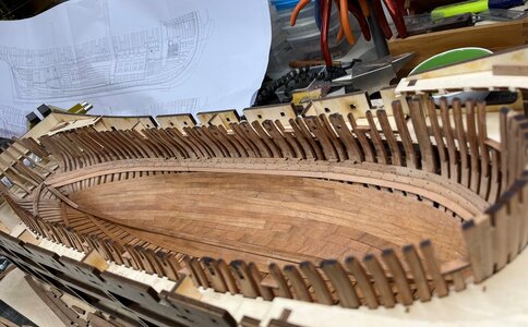
still there are some gaps of planking which have to be filled and closed
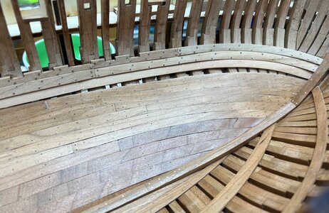
good to have the excess laser cut planking of the other side, so enough material for such filling pieces
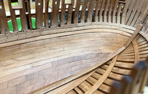
and als the area at the stern are closed now, technically not really correct, but the planking is closed and "fixed" with treenailing
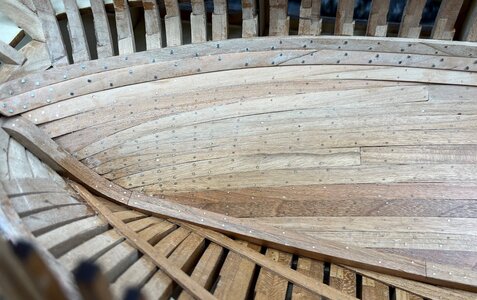
Many Thanks for your interest in my work and building log ..... to be continued ......
I agree, Yes - it can be done....
not easy, but with the good quality timber and some patience it is possible to get an acceptable result.
I mentioned already the thrid clamp plank. In the kit you can find the plank "D" for the adjustments between the clamps and the inner planking

Looking at the cross section in the Anatomy book from Goodwin we can find the plank "51" marked with the red arrow as a thick stuff upper strake planking

so I decided to use the kit plank "D" and used the form as a template for a scratch plank of bigger thickness, so I prepared a 2,2mm thick sheet (with my small turkish thicknesser from Netmak) and praped this plank
starting point is the midship

also the bow - I used here copper nails as bolting in order to get a more visible difference to the clamps

and finally also the plank direction towards the stern


still there are some gaps of planking which have to be filled and closed

good to have the excess laser cut planking of the other side, so enough material for such filling pieces

and als the area at the stern are closed now, technically not really correct, but the planking is closed and "fixed" with treenailing

Many Thanks for your interest in my work and building log ..... to be continued ......

Last edited:
- Joined
- Jan 9, 2020
- Messages
- 10,566
- Points
- 938

Hi Uwe. This is NOT criticism; I am asking the question because I am intrigued by this. I know that you are a most meticulous and experienced builder and that CAF's models are well designed and properly tested in test-builds. What could be the cause/s of these gaps in the bottom planking? Surely, something is not right here - those gaps are simply too big? Or are those gaps supposed to be left open?
You can not find any clear drawing in the Anatomy book, or also no information in the contemporary drawings, how the inner planking was made .Hi Uwe. This is NOT criticism; I am asking the question because I am intrigued by this. I know that you are a most meticulous and experienced builder and that CAF's models are well designed and properly tested in test-builds. What could be the cause/s of these gaps in the bottom planking? Surely, something is not right here - those gaps are simply too big? Or are those gaps supposed to be left open?
According Lavery often the inner planking was not completly pulled up or closed to towrards the clamps. Often the bigger ship of the lines had a carpenter walk slightly under the waterline in order to check the status of frames and the watertightness of the outer planking. For this the inner planking had to be open......
And in addition it seems, that I made a mistake with the installation height of the clamps towards the stern - at the bow it is definitely correct, but going backwards there is a problem, which I have to solve somehow. The height of the mortar bed beams have to be correct.
Maybe also an additional reason could be, that I started with the first inner planking rows to much fore, with this the gap would be also bigger.......
For a model designer like CAF, it is extremly hard to find the absolute correct way and prepare the planks that everything of such planking fits by 100% - unfortunately modelers are making mistakes, and CAF supported us with the plank "D" which is wider and suppost to be for adjustments
I personally decided to close the planking towards the clamps for the mortar beds and the area higher towards the deck beam clamps will be open (for the carpenter).
Later or at the end we know more
- Joined
- Jan 9, 2020
- Messages
- 10,566
- Points
- 938

Thank you very much for the reply, Uwe. As I said, I was just trying to understand all the factors that are at play here. Le Coureur did not seem to present the same issue, but she was obviously a much smaller ship and there were no mortar beds to take into account.You can not find any clear drawing in the Anatomy book, or also no information in the contemporary drawings, how the inner planking was made .
According Lavery often the inner planking was not completly pulled up or closed to towrards the clamps. Often the bigger ship of the lines had a carpenter walk slightly under the waterline in order to check the status of frames and the watertightness of the outer planking. For this the inner planking had to be open......
And in addition it seems, that I made a mistake with the installation height of the clamps towards the stern - at the bow it is definitely correct, but going backwards there is a problem, which I have to solve somehow. The height of the mortar bed beams have to be correct.
Maybe also an additional reason could be, that I started with the first inner planking rows to much fore, with this the gap would be also bigger.......
For a model designer like CAF, it is extremly hard to find the absolute correct way and prepare the planks that everything of such planking fits by 100% - unfortunately modelers are making mistakes, and CAF supported us with the plank "D" which is wider and suppost to be for adjustments
I personally decided to close the planking towards the clamps for the mortar beds and the area higher towards the deck beam clamps will be open (for the carpenter).
Later or at the end we know more
I have to be honest - also with the Coureur I had my personal problems (not caused by the kit) with the inner plankingThank you very much for the reply, Uwe. As I said, I was just trying to understand all the factors that are at play here. Le Coureur did not seem to present the same issue, but she was obviously a much smaller ship and there were no mortar beds to take into account.
So I am unfortunately not the best inner planking modeler
- Joined
- Jan 9, 2020
- Messages
- 10,566
- Points
- 938

No, I don't think that at all!I have to be honest - also with the Coureur I had my personal problems (not caused by the kit) with the inner planking
So I am unfortunately not the best inner planking modeler
I also had the problems with Le Coureur that the floorboards were not exact, I also had to improve them, so I don't think it's your fault, Uwe.
Hallo my friends,
many thanks for all your kind words and comments - much appreciated
and also for the likes received - completely motivating that there is an interest in my progress
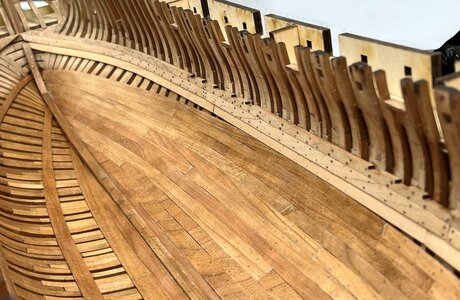
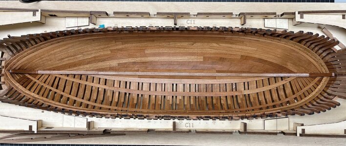
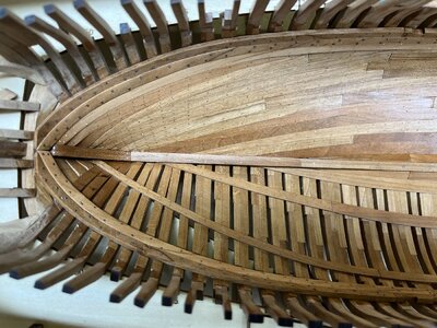
I finished also the clamps on the other side, so that I was able to treat the next areas with CLOU Schleifgrund - and I am by myself very pleased by the appearance ....... there for some more photos of this status, I hope you like it also
also fro everybody, who will build this kit, these photos could help as an example of how to make it, or not to make it (when I figgured out where my mistake, described in the previous posts, was)
First of all the birds view
and with a closer distance
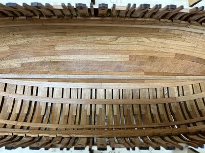
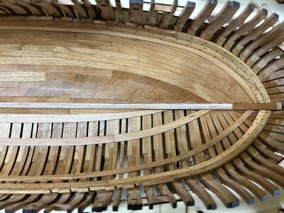
the side views
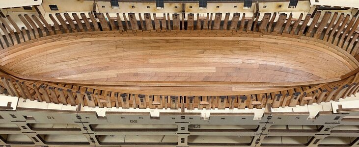

and longitudinal
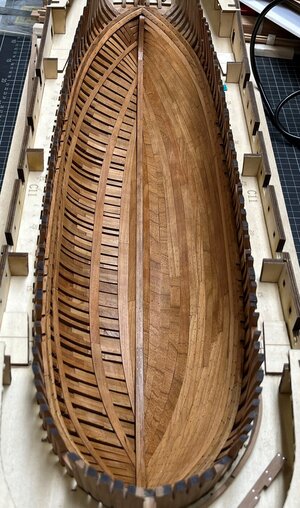
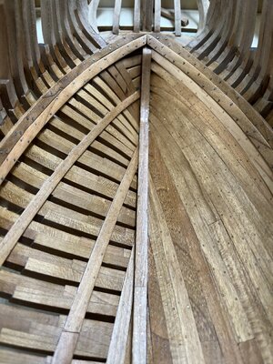
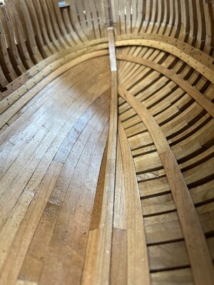
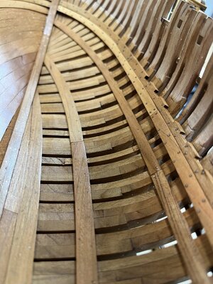
and for everybody not bored already
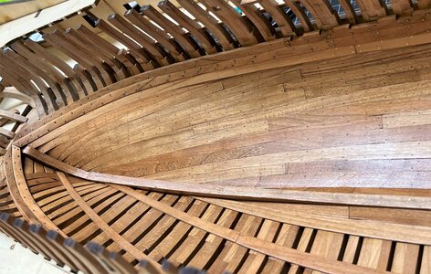
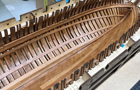
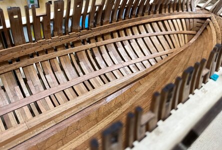
Looking good, or?
But......
interesting is this view where we can see some smaller inaccuracy in the line of the clamp
Very good, that later on with installed interior, the riders, beams and all this, nobody can look along the line of the clamps - the clamps will be everywhere only over a length of some centimeters visible - puh
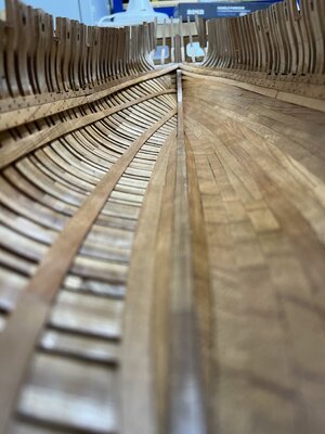
Many Thanks for your patience to take a look at these photos ..... to be continued in short time with the mortar beds
many thanks for all your kind words and comments - much appreciated
and also for the likes received - completely motivating that there is an interest in my progress
I finished also the clamps on the other side, so that I was able to treat the next areas with CLOU Schleifgrund - and I am by myself very pleased by the appearance ....... there for some more photos of this status, I hope you like it also
also fro everybody, who will build this kit, these photos could help as an example of how to make it, or not to make it (when I figgured out where my mistake, described in the previous posts, was)
First of all the birds view

and with a closer distance


the side views


and longitudinal


and for everybody not bored already


Looking good, or?
But......
interesting is this view where we can see some smaller inaccuracy in the line of the clamp
Very good, that later on with installed interior, the riders, beams and all this, nobody can look along the line of the clamps - the clamps will be everywhere only over a length of some centimeters visible - puh

Many Thanks for your patience to take a look at these photos ..... to be continued in short time with the mortar beds
- Joined
- Jan 9, 2020
- Messages
- 10,566
- Points
- 938

Hi Uwe. let's ignore the view along the clamps (last picture) and focus on the actual planking. That is very well done and now that it is all closed up, it looks excellent. Your choice to opt for the CLOU was an inspired one - one simply cannot believe the difference that it makes! Looking good!
Hallo Uwe, exceptionally nice planking. The nail work looks very good. The overall picture is absolutely coherent.
- Joined
- Jul 24, 2022
- Messages
- 79
- Points
- 78

Very fine and intricate work here. Very well done. I'm a little envious, I don't know that I could ever take on a POF build.
Many Many Thanks my friends - for the nice comments and all the Likes received
I am very happy, that so much members and friends are following my building log - Great
Now it was time to go further with the beams of the mortar beds, which are based in the prepared notches of the clamps - hoping that the will fit in the height, because these are also laying on top of the shelves or better shell racks
-> each beam has 3 contact points on the 3 racks and left and right on the clamps - all of them should fit...... let us see
Beams are prepared and laying on the clamps - and you can see the base beam of the racks on top of the riders
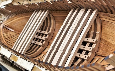
and the same situation with the view from the top
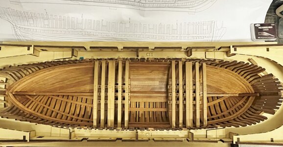
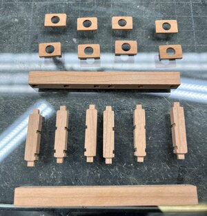
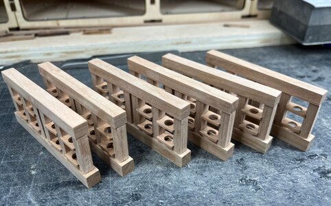
the elements of one shell rack - On one rack 8 shells have their base - 6 racks all together, with 3 racks under each mortar
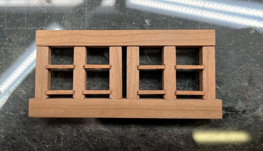
first dry-fit - some smaller sanding works are still necessary
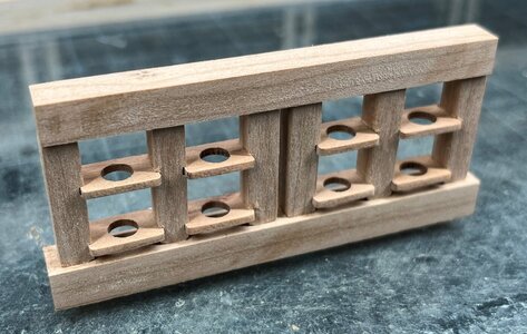
and the finished racks
a first test with some of the balls / shells (included in kit)
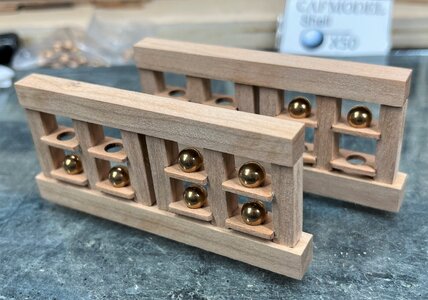
prepared and ready to be installed on the riders
in my next posts you will see my report of the fitting the correct height
..... to be continued ......
I am very happy, that so much members and friends are following my building log - Great
Now it was time to go further with the beams of the mortar beds, which are based in the prepared notches of the clamps - hoping that the will fit in the height, because these are also laying on top of the shelves or better shell racks
-> each beam has 3 contact points on the 3 racks and left and right on the clamps - all of them should fit...... let us see
Beams are prepared and laying on the clamps - and you can see the base beam of the racks on top of the riders

and the same situation with the view from the top

the elements of one shell rack - On one rack 8 shells have their base - 6 racks all together, with 3 racks under each mortar

first dry-fit - some smaller sanding works are still necessary

and the finished racks

a first test with some of the balls / shells (included in kit)

prepared and ready to be installed on the riders

in my next posts you will see my report of the fitting the correct height
..... to be continued ......


