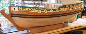
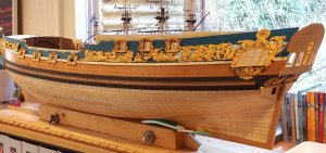
HMS Royal Caroline kit ZHL 1/30

Hi Greg,

I will be thickening the sides by using the remainder of the first layer plancking of which I still have more then plenty available.

Interesting thought!
What thickness will you be doing. Will it be an universal thickness from decking to top Rail?
Thanks mate and havagooday
Greg
 
Hi greg,

I will follow the AotS drawings in combination with the maximum size of the rop rail supplied with the kit. I will create also a tapered construction which also allows me to hide the wiring for the lighting.
Regs Maarten
 
Hoi Maarten, you got a great talent of mastering problems and details on your beautiful model.
I like the way how you bring the solutions into your log.
Gr. Jos.
 
G'day Maarten I see you are doing a great job on your Royal Caroline, I'm looking forward to your cabin layout, it looks quite interesting, I'm sure the King and his Queen will much appreciate all your effort.
As regards the template I don't think the problem is the template, which as you say when you put it over the AOTship drawing it is OK, the real problem is that the model itself is not as long as the drawings, that is what I was saying in my log that if I could start again I would another inch to inch and a half to the keel to extend it.
On the AOT ship drawings the cabin roof with out the over hang at the front is 22cm and on the model it is 21cm, and the distance from the transom to the cabin roof is 25cm on the drawing and only 23.5cm on the model, I notice you had to trim your eagles wing right back to get it to fit, I went both ways with mine and trimmed some of the Eagles wings and I will also have to trim some of the carving just behind the fourth gun port, so I think that if the keel had an extra 15mm behind the cabin and an extra 15mm just behind the fourth gun port, things would have been a lot easier, these measurements are approx only.

looking forward to the rest of your build,

best regards John.
 
Last edited:
Hi John,

I will add some 5 mm to the fore castle and my galleries are a few mm more to the stern, this creating some additional space. Indeed I still have to trim an eagle, that avoids him from flying away :-). By fitting and trimming the final result will still be beautiful, the result of the beautiful kit.

Just as you say, adding some 15 mm to the keel in the middle would be the best solution, but to late for that.

Regs Maarten
 
G'day Maarten, as you say it's too late for us, I just mentioned it again in case that someone who is going to build her reads this, and as you say she is still is a beautiful ship, and I am enjoying your build of her,
Best regards John.
 
G'day Maarten and John
It is very interesting how both of you describe your solutions and what you would have done.
I thank you both so much.
As you mentioned John about the distance from the transom to the main cabin is different of 15mm. This particular measurement is what I've discovered was wrong in the kit. I'm not using the last bulkhead (12) as a bulkhead.
As I was doing my measurements, I discovered that the transom should be 16.5 mm further aft. If you look at the small A4 sheets booklet with the diagrams of the interior section there's a red line drawn on it. This red line is what you get by using bulkhead 12 and this what I believe is part of the problem. This is why I'm only using the bottom section only where the 2 potholes are.
So I will be extending the transom aft by 16.5 mm.
Now regarding the middle section, I wasn't planning to do any extension of the keel, but I can extend the distance by 5mm each between bulkheads 7-8 and 8-9 to get some extra length. This is where there is hardly any curve in the hull.
So in summery, if I get 10mm extra in the middle plus the 16.5 at the stern, I would have 26.5mm extra in length over-all, than each of your models. The extra 10mm will be in front of the main cabin. Do you both think, this would be enough?
I don't want to make these areas any longer because of the decking etc.
One problem that I might get if I do this is that there would be 10mm extra distance from the main and forward masks or between the main and the mizzen.
Again do you think this would be a problem?
Havagooday mates
Greg
 
Last edited:
Hi Greg,

The 2,6 mm is more then sufficient, for the carvings you need some 15 mm.
If I were you I would follow the aots drawing as the carvings are spot on if you put them on the drawings. In the drawings you can also determine what happens with the masts. I havent done all these measurements. Can you see it in your digital drawings, or is this just the waterlines?

Regs Maarten
 
Well just for my own satisfaction and for anyone who might build the Royal Caroline, I got out the drawings and measured them against the model I am building,
From the transom to the front of the figure head on the AOTship drawings the distance is 1100, and on the model the distance is 1055, so the model is 45mm shorter than the AOTship drawings. This causes some problems when attaching the carvings along the sides of the ship, I didn'nt know about this till I started attaching the carvings and subsequently I had to trim the carvings to get them to fit.

So I took some further measurements to find out where the differences were, from the front of the figure head to the first bulkhead on the bow,
on the drawing it was 123mm and on the model it was 110mm, 13mm difference,

there is not a lot you can do about this area, the main ones are the next three areas that I measured where the carvings fit along the hull

then I measured from the bulk head on the bow to the end of the last cupid on the fourth gun port , on the drawing it was 415mm and on the model it was also 415mm, no difference,

then I measured from the end of that last cupid to the back of the cabin, on the drawing it was 305mm and on the model it was 290mm, 15mm difference, so if you are going to extend the length of the model you need to cut the keel and insert a strip of ply the same thickness as the keel and 15mm wide, preferably in front of the main mast, if you do this the carving will sit in place quite comfortably


then I measured from the back of the cabin to the back of the transom, on the drawing it was 255mm and on the model it was 240mm, 15mm difference, also you would have to do the same right behind where the main cabin ends, there are several other things as well but these are the main changes to get all the carvings to sit in place without having to trim them like I had to.


all the differences add up to 43mm, which is close as to the 45mm overall difference

also Greg wanted to know the width of the main cabin, at the front it was 215mm on the drawings and 203mm on the model, at the back where it narrows it was 192mm on the drawings and 178mm on the model,

all the above measurements are give or take a mm,


happy modelling,

best regards John.

PS I will post this on my own log also, so if you wish to delete it Maarten, I understand.
 
Last edited:
  • Like
Reactions: Jos
Hi John,

Thx for the measurements, great explanation. I will tackle these issues along with the rest of the build. I am curious why they did it like this. Looks like they first developped the kit, drunk some beers most probably and then decided to add the AotS drawings.

I am still very happy with the kit and this adds an extra challenge.

regs Maarten.
 
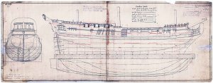
I can explain the width issue' remember when I told you that the waterline didn't make sense from the AToS and the Swedish draft, and I got the same result when I plotted the drawings myself. My only explanation were that the plan size was taken from the Royal CAROLINA and not for the Royal CAROLINE.
I worked out that the plan view width have to condensed by 94.4%, but leave the lengh the same size.
It's too late in the morning for working out the percentages of the different width, but I would assume it's are about 94% or so.
When I was doing research years ago on the RC, I discovered that the designer of both THE ROYAL CAROLINE and CAROLINA, which was a larger yacht than the RC was a Swedish. I can't remember his name. Just after the RC was built he left England and took the drafts of the RC with him.
CAROLINE DRAFT.jpg
That is why you can only get the original drafts of the RC from the Swedish Martine Museum.
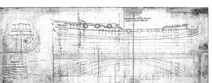
I apparently he also took the CAROLINA drafts as well, Maybe (only, this is only my an assumption) the Swedish drafting section could have mixed them up. Who knows now!
CAROLINA DRAFT.jpg
As I have stated, all of this is my assumption.
My nephew is an naval architect and years ago, when I was have a conflict with the waterline versus the bulkheads profiles. I sent him my files. He got back to me and he said, I was correct and the profile of the ship was too wide.
I reduce the width of the profile by 94.4% and that is what I'm working on. I reprinted the plans only at this scale, and this is my version that's I'm working on. Both Max and I must have came to the same conclusion when he drew up the bulkheads for this kit.
I hope this makes sense to you all, but I'm writing this early in the morning.. My apologize if it's hard to read and understand.
Havagooday to all
Greg
Time of this post: 3.50am.

Ps. I'm a bit more awake now (about 6.40 am), and I worked out that the measurements that John gave me and they are : ........ wait for it.................................94.4186%
I was quite close, I only ask John for confirmation of my readings.
Havagooday again
Greg
 
Last edited:
As all can see above there is more to this kit that you see at first. Not a kit for a starter as you have to work around some issues, but the blogs will offer help for anyone who likes to build this vessel so he can sort out the issues before starting the build and won't find any suprises.

Back to the build. At the moment I am working on building the rear cabin which is the kings bed and day room. Before building I first have to find a solution for fitting the battery case and the wiring for the lighting.


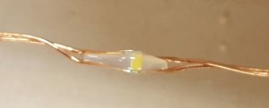
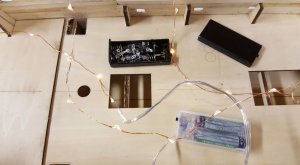
As lighting I use a christmas light set of micro LEDs, these are mounted in paralel on the wire, this means you can cut the wire where ever you want to get the amount of LEDs you want. I will fit the LEDs on the deck beams which will be fitted afterwards, most probably 3 or 4 LEDs per beam. The wiring to these LEDs I will use as supplied in the kit. I have also bought some mini LEDs to simulate candle light. The LED's supplied with the kit are red in colour and can be seen in the picture in the black battery box.
Cabin LED 1.JPGCabin LED.JPG


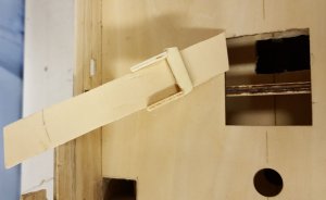
For the battery case I have created a hole in the lower deck below the grating opening just before the main mast. This grating I will fit so you can open it to switch the lighting on and off. To fit the battery box I have fitted a slide way into the hull to easily slide the battery box in and out for replacing the batteries.
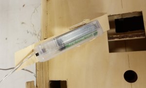
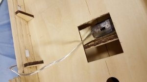
Battery slide.JPG
Battery slide 1.JPGBattery box.JPG

Now it is time to open the cabin and remove the frames.
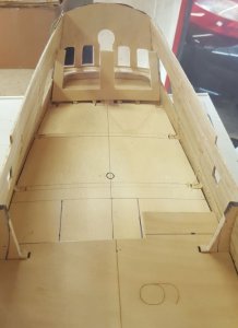
Cabin9.JPG
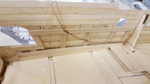
The wiring I hide in the "walls" the inner side of the hull. As I remove all the inner ribs above the deck level I will strenghen the hull by creating a sandwich construction by using the remaining planks from the first planking.
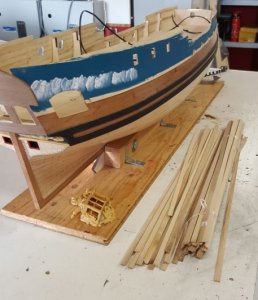
Cabin 8.JPG
In the sandwich walls I will fit the wiring.
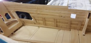
Cabin 6.JPGCabin 7.JPGCabin 5.JPG
On top of the sandwich construction the new deck beams will be fitted at the marked spots, this according the AotS drawings.
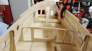
Cabin 4.JPG
Dry fitting the new bulkhead, front side of the bed-day room.
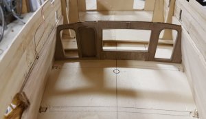
Cabin10.JPG
I have veneered the bulk head with wallnut planks, finishing still needs to be done, the open space is for the bed.

For decorating the room I have searched the internet for Georgian furnishing and decoration and googled for Georgian wallpapers. For this cabin the picture below shows the selection for the wall paper. In reality most probably the spaces would have been painted as in the humid environment wall paper is not a great solution :-) but this image looks like being painted as well.
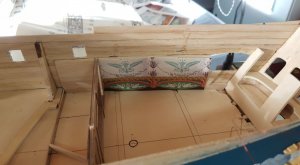
Cabin 3.JPG
For the deck I have selected a rich decorated parqueterie floor, all this will be lacquered with clear varnish when fitted. Picture below just to give you an idea.
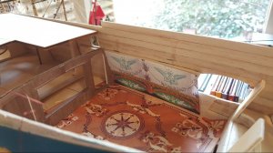
Cabin 2.JPG
And if we look through the cabin window, ooohhhh.
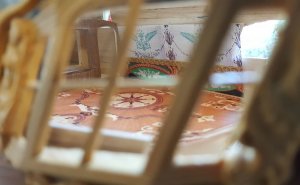
Cabin 1.JPG
 
The carvings are also making progress, and while not working on it I put it aside like this just to already enjoy the beautiful lines of this magnificent ship.
Accept for the gallery all decorations are just loosely on the model, kept in place by gravity.
PS side ornaments 1.JPG
PS side ornaments 2.JPG
See you next time and enjoy the comming modelling weekend.

Regards Maarten
 
Hoi Maarten,
I want to give you a compliment on the interior and lightning solution.
Great build.
Gr. Jos.
 

BRILLIANT!
G'day Maarten
The work and your brain power that you have done is an inspirational to anyone who is going too, or is building this amazing kit.
I thank you so much for giving me some ideas for my build.
Are the wall carvings on the wall paper made from wood or a print out? If it's a printout it's looks real, if it's a wood carving, where did you get it?
Havasafe skiing trip next weekend for you, your family and friends.
Havagooday mate
Greg
 
Hi gents,

Thx for the comments.

Greg it is just a print out from an internet site from georgian wallpaper prints. I have manipulated these in Powerpoint to fit them in size and pattern.
I will check if I still have the link and post it.

I am thinking of maybe put a wooden profile strip in between of the upper and lower wallpaper to get an optimum 3d simulation. In those days they used a lot of these painting techniques which is called trompe l'oeuil. With this they created effects like marble, wood prints etc. You see this also a lot in palaces around Europe. See an example here in the link of this technique.
http://www.vanhoef.com/nederlands/trompeloeil1.html
I guess these techniques were used in those days in a royal yacht like this. The AotS drawings show also decorations on the cabin walls.
 
Hi ADC,

Yes the floor is also paper.
The current pieces are a test print. The final fitting will be of thicker paper to get a higher quality print. Then I will apply a layer of clear varnish so it will be unrecognizable as being paper. We have to learn something from the amazing papermodellers out there like Jos or Doris.

Regs Maarten
 
Back
Top