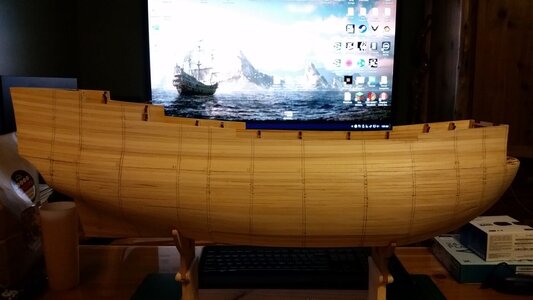
Fantastic Kurt. She has lovely lines!
-

Win a Free Custom Engraved Brass Coin!!!
As a way to introduce our brass coins to the community, we will raffle off a free coin during the month of August. Follow link ABOVE for instructions for entering.
-

PRE-ORDER SHIPS IN SCALE TODAY!
The beloved Ships in Scale Magazine is back and charting a new course for 2026!
Discover new skills, new techniques, and new inspirations in every issue.
NOTE THAT OUR FIRST ISSUE WILL BE JAN/FEB 2026
You are using an out of date browser. It may not display this or other websites correctly.
You should upgrade or use an alternative browser.
You should upgrade or use an alternative browser.
HMS Sovereign of the Seas - Bashing DeAgostini Beyond Believable Boundaries
- Thread starter DARIVS ARCHITECTVS
- Start date
- Watchers 105
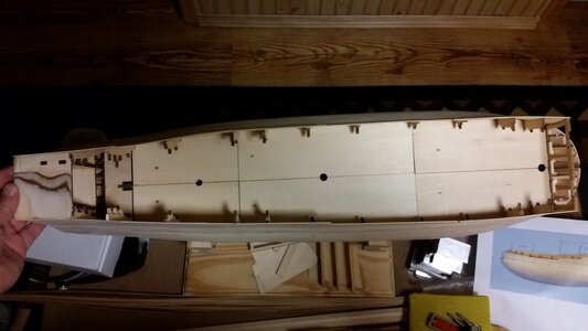
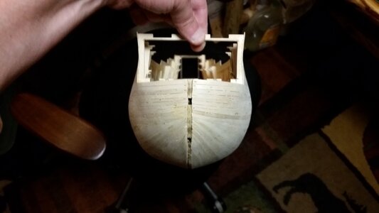
Sorry for sending out replies for every single tiny step in this build. Other activities are competing for my time and work on the ship has slowed. The transom piece fits the parts it is mounted to perfectly after being curved at the bottom edge. Time will tell how much the guts in the stern castle will be changed as the build progresses and interior features are contemplated.
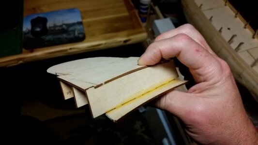

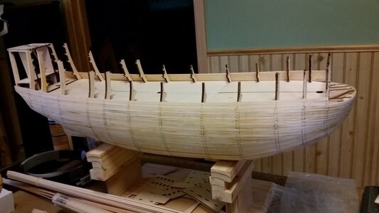
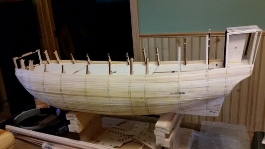
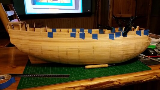
More planking up the sides. A few more strakes to go. I didn't use the plywood pieces for the sides of the stern castle, since the side galleries will be custom made and altered. After the first layer of planking done, the hull will be sanded, and the plywood for the upper gun deck will be removed and scratch build construction of the lower gun deck will begin. The limewood on the upper sides of the hull is noticeably smoother than the basswood below it, but all of it will be smooth after sanding.
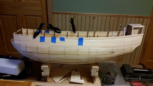
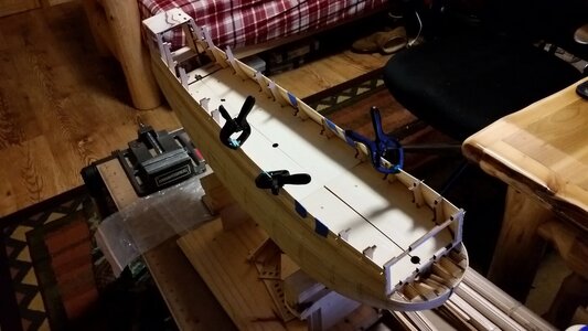


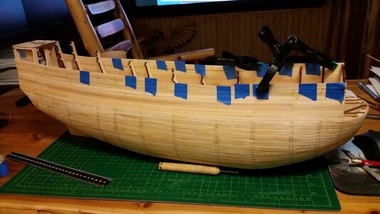
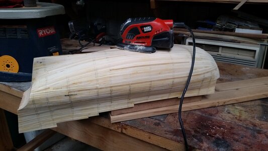
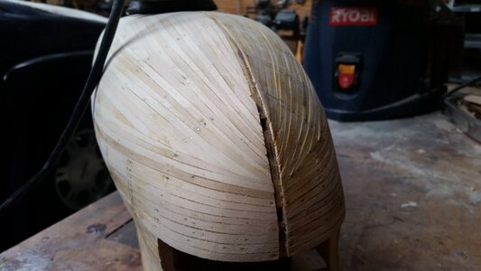
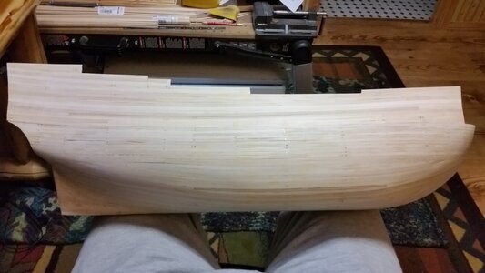
The first layer of planking on the sides of the hull is complete, and the new step in the instructions is to trim the top edges of the gunwales to the proper profile. Before that, I'm going to sand the sides of the hull. The stern is remaining unplanked to allow access to the interior of the stern castle at this time. Masking tape and clamps help hold unsupported plank strips in place until the glue dries. Pins are used, and later removed, where the frames offer support. The hull looks rougher than it is, but will look better after sanding.
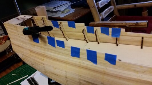
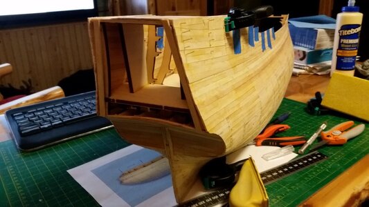
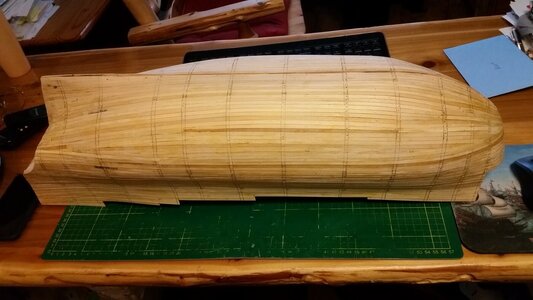
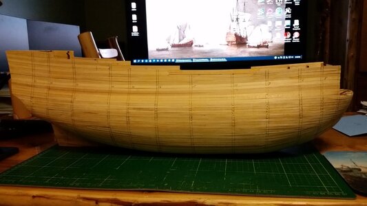
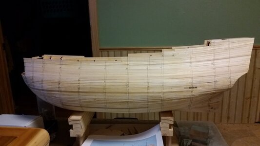
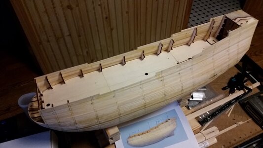
The model is at this stage in the instructions, with exception that the plywood on the sides of the stern castle is not being use.
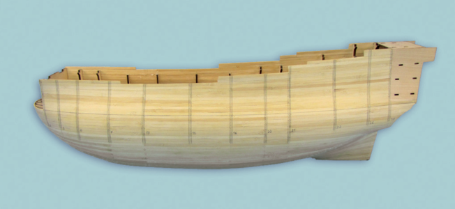


The model is at this stage in the instructions, with exception that the plywood on the sides of the stern castle is not being use.

Congratulations Kurt. This is a major accomplishment. Maybe not technically demanding but laborious and time consuming. Happy sanding!
Try as I might, I won't be able to catch up to you Paul!Congratulations Kurt. This is a major accomplishment. Maybe not technically demanding but laborious and time consuming. Happy sanding!
Congratulation for reaching this important step - looking good
If you or Nigel have ANY ideas on alterations on gun port placement, I am eager to hear them. NOW would be a good time to discuss such enhancements before I start cutting holes in the hull! Your log and Nigel's are the two primary sources I have for altering the DeAgostini model into something much more details and better. I am aware that the gun port the intersects the side gallery was a feature that may have been incorrectly left over from the original design and should not have appeared in that position after the 1650 rebuild of the ship. It appears that the gun port is below the level of the deck, and we know the decks were continuous from stem to stern.Congratulation for reaching this important step - looking good
- Joined
- Apr 20, 2020
- Messages
- 6,248
- Points
- 738

התקדמות גדולה, כל הכבוד אגודלים למעלהשכבת התכנון הראשונה בצידי גוף השלמה הושלמה, והשלב החדש בהוראות הוא לקצץ את הקצוות העליונים של האקדחים לפרופיל הנכון. לפני כן, אני הולך לשייף את דפנות הגוף. הירכתיים נותרו ללא סיפון כדי לאפשר גישה לחלק הפנימי של הטירה הירכתית בשלב זה. נייר דבק ומהדקים עוזרים להחזיק רצועות קרשים לא נתמכות במקום עד שהדבק מתייבש. משתמשים בסיכות ומוסרות אחר כך, כאשר המסגרות מציעות תמיכה. הגוף נראה מחוספס יותר ממה שהוא, אך ייראה טוב יותר לאחר השיוף.
View attachment 234019
View attachment 234020
View attachment 234021
View attachment 234022
View attachment 234023
View attachment 234024
הדגם נמצא בשלב זה בהוראות, למעט כי לא משתמשים בדיקט בצידי הטירה.
View attachment 234025
Thanks, Shota70!Great progress, well done thumbs up
Since the lower gun decks will be not be altered as far as vertical position, the DeAgostini instructions were followed to draw the frame lines on the outside of the hull. This was done using 3/32" pinstripe tape, and running a mechanical pencil along the edges of the tape for each of the frame lines. The frame lines were numbered for reference. The gunwale edge near the top of the hull planking was measured according to the instructions and marked. The excess planking beyond these lines will be removed later. The upper gun deck plywood pieces were unpinned and removed, as well as the temporary deck beams that supported them. This will allow access once again to the lower gun deck for interior work such as planking and adding anchor tackle and other interior features.
Last piece of red pinstripe tape remaining
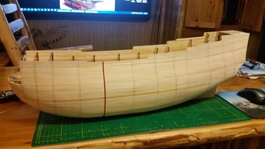
Forecastle gunwale line drawn
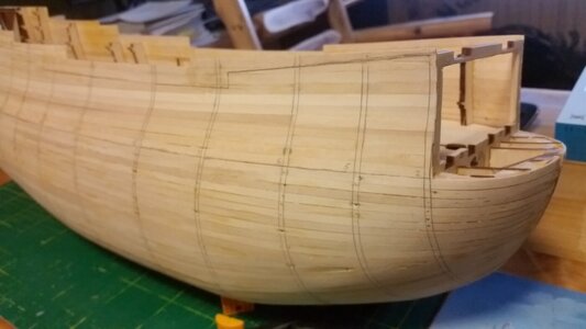
Waist gunwale line drawn
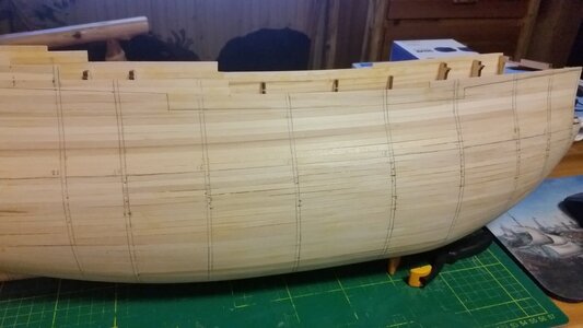
Sterm gunwale line drawn
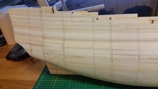
Removing upper gun deck pieces
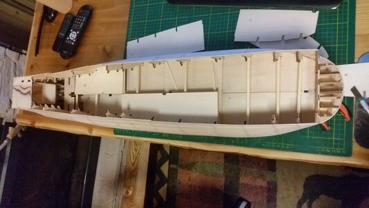
Temporary beams will be removed
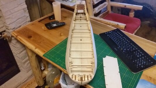
Lower gun deck is clear for access once again
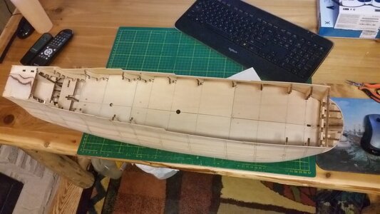
Last piece of red pinstripe tape remaining

Forecastle gunwale line drawn

Waist gunwale line drawn

Sterm gunwale line drawn

Removing upper gun deck pieces

Temporary beams will be removed

Lower gun deck is clear for access once again

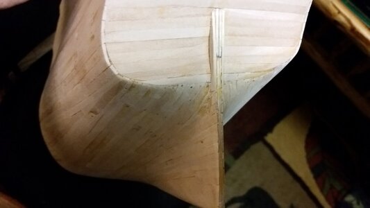
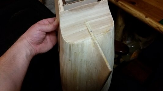
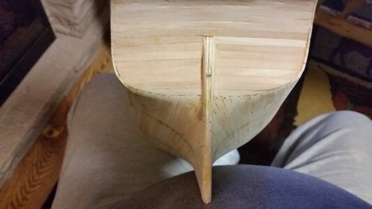
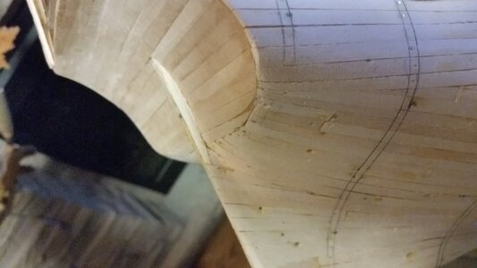
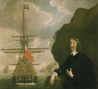
Did a little tweaking to the shape of the tuck. It doesn't appear as rough and wide with some subtle shaping. The DeAgostini stern tuck is very wide and difficult to make it appear anything like the Lely Portait of Peter Pett. As you move downward, the transition from a hard line at the edge of the transom to the round tuck is difficult to achieve. The second layer of planking will be arranged to better fit the pattern as seen in the Portait of Peter Pett.


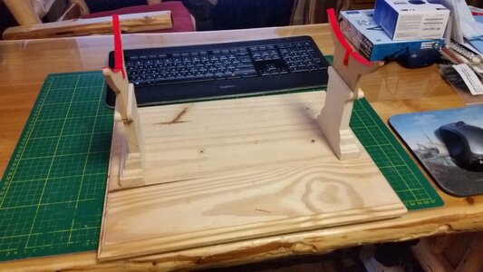
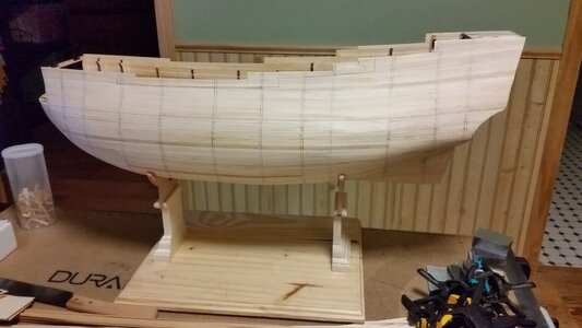
Because the hull does not have a keel, I converted the work stand previously used for holding the hull inverted for planking the bottom to have saddle mounts for holding the hull properly upright. A couple strips of red cloth glued to the oak saddles will prevent he hull from scratches. The bottom plaque was re-used, and the bottom parts of the stanchions was made from left over molding that was bought for the glass riser built for the display table for the La Couronne model. A couple hours on the band saw, some sanding, and saddle fitting to the hull, gluing, and the stand is ready. It's very sturdy and stable. I do not know if the keel on this model will be attached strongly enough to used the multi-position keel vice that I built and used earlier. Would you guys trust holding the model with a keel vice? La Couronne's keel was part of the false keel plate of the model frame, and very strong. I don't want to accidentally bump the model late in the rigging phase and hear that *CRUNCH* sound of the keel snapping off. 


I realize you are asking SoS builders your question but I thought I'd weigh in anyway. There is no way I would trust the glue joint between ply edge and ply edge on these DeAg models. It's super inconvenient to work from a saddle and I sometimes find myself laying my ship back in the saddle (rotating it longitudinally) but I did not have the confidence level I thought I should have in using a gimbaled keel clamp. My saddle arms are a bit taller than yours...Because the hull does not have a keel, I converted the work stand previously used for holding the hull inverted for planking the bottom to have saddle mounts for holding the hull properly upright. A couple strips of red cloth glued to the oak saddles will prevent he hull from scratches. The bottom plaque was re-used, and the bottom parts of the stanchions was made from left over molding that was bought for the glass riser built for the display table for the La Couronne model. A couple hours on the band saw, some sanding, and saddle fitting to the hull, gluing, and the stand is ready. It's very sturdy and stable. I do not know if the keel on this model will be attached strongly enough to used the multi-position keel vice that I built and used earlier. Would you guys trust holding the model with a keel vice? La Couronne's keel was part of the false keel plate of the model frame, and very strong. I don't want to accidentally bump the model late in the rigging phase and hear that *CRUNCH* sound of the keel snapping off.
View attachment 234976
View attachment 234977
BTW: the whole setup looks quite tall. Is your table really short or do you work standing up?
Hi Paul! You do realize you're one of the SoS builders, don't you? (a prominant one at that) You're right about the plywood edges. Even Titebond II will pull bits of wood out of the edge of a piece of the plywood if you test the joint to destruction. Since the keel will probably be fabricated to replace the crappy plywood one, perhaps a series of thing wooden pins (toothpicks?) can be used to hold the keel onto the plywood false keel with sufficient strength to all use of a keel vice.I realize you are asking SoS builders your question but I thought I'd weigh in anyway. There is no way I would trust the glue joint between ply edge and ply edge on these DeAg models. It's super inconvenient to work from a saddle and I sometimes find myself laying my ship back in the saddle (rotating it longitudinally) but I did not have the confidence level I thought I should have in using a gimbaled keel clamp. My saddle arms are a bit taller than yours...
BTW: the whole setup looks quite tall. Is your table really short or do you work standing up?
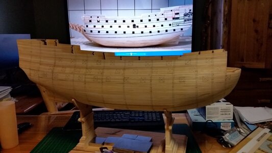
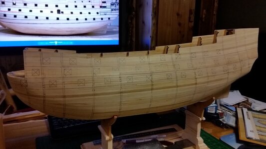
The stand height was chosen such that when the model is placed on my 32" high desk, the side of the ship is at shoulder height while I'm sitting in the computer chair. This is great for the next step of drawing the cannon port holes with pencil on the hull. Next to the desk is a 22" high portable workbench. Because it's lower, I can work on deck fittings and lower rigging. Work on the upper rigging will be down while standing if I have to use the saddle stand. That's why I want to go back to the multi-position keel vice. I can tip the entire ship at 45 degrees with the masts angle toward and easily work on the upper rigging, as well as reach between lines to access the deck. Still doubting if even a reinforced keel attachment will be strong enough, especially now that this model as all those balsa blocks packed into the hull, unlike La Couronne. Guess we'll find out...
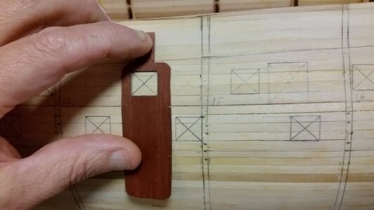
Today was spent measuring and drawing the gun port locations on the hull. The Deagostini model does not feature the forward most guns, port and starboard, on the lower gun deck. These are located at below the rear end of the beakhead. Why they forgot these, I don't know.  The ports were added, and later the solid wood behind then will have to excavated out with a drill and sharp wood chisel to make room for a false deck and cannon carriage. The rear-most gun ports that are under the side galleries have not been drawn yet. For the earliest version of this ship, these guns would be on the same deck as the upper gun deck, but it seems that more than one artist has depicted them at a lower level than would be possible if they were on that deck. This poses a problem since it is well documented that all three of the continuous gun deck were flush and continuous, with no sub decks above or below them in the stern. Some later artists have reconciled this by adjusting the position of the side galleries and the gun ports so the after most guns line up and appear to be on the same deck as guns farther forward. Many model maker ignore the problem entirely and place the guns as they are depicted in Payne and Willem Van de Velde's pictures, about 1/4 of a deck's height lower than the guns farther forward. More study of the vertical placement of these guns is necessary at this point.


Last edited:

