Hey Kurt, the middle row seems to run downhill to the stern - is that correct?
-

Win a Free Custom Engraved Brass Coin!!!
As a way to introduce our brass coins to the community, we will raffle off a free coin during the month of August. Follow link ABOVE for instructions for entering.
-

PRE-ORDER SHIPS IN SCALE TODAY!
The beloved Ships in Scale Magazine is back and charting a new course for 2026!
Discover new skills, new techniques, and new inspirations in every issue.
NOTE THAT OUR FIRST ISSUE WILL BE JAN/FEB 2026
You are using an out of date browser. It may not display this or other websites correctly.
You should upgrade or use an alternative browser.
You should upgrade or use an alternative browser.
HMS Sovereign of the Seas - Bashing DeAgostini Beyond Believable Boundaries
- Thread starter DARIVS ARCHITECTVS
- Start date
- Watchers 105
I believe that sudden downward placement of the last two gun middle gun ports on each side at the stern is one of the mysteries involving this model. I mentioned this in post #230 earlier. Payne and Willem Van de Welde both show those two gun ports on the end seemingly a meter or two below where you think the gun deck would be if you are following the sheer lines (planks and side galleries) of the vessel. However, we know that HMS Sovereign of the Seas was required to have three continuous, uninterrupted flush gun decks below the castles. There is a long discussion on the MSW forum about this. Frank Fox, an expert in 17th century vessels, said that the gun port do not follow the sheer lines of the hull, they follow the overall hull shape, the curvature of which is much flatter than the sheer lines. So, even though the planks run along this deep curve, the hull does not. When you see the lines of guns and the slant of the planks and side galleries together, the gun ports don't line up elegantly. The line of ports seems almost flat, even though there is some curve. I believe that artists drawing the lines of ports have to be regarded with caution regarding gun port placement. Behold how those brazen lines of guns dare cross the lines of the wales!Hey Kurt, the middle row seems to run downhill to the stern - is that correct?
So what do I do with those confusing gun ports? I do not think they should "run downhill" as you approach the stern. Logic tells me the best thing to do is position the deck for these guns as an extrapolation of the middle gun deck, and adjust the side galleries such that they are where they appear to be in the paintings/woodcuts relative to the guns. The gun decks as viewed from the side should line up with the stern chaser gun placement just just. A modeler on MSW already figured that out and came up with a computer generated model using Blender 3-D that shows this. The proportions and shape of my model may look a little different than the artists' conceptions, but it will probably be a more realistic representation of a working ship.
Payne shows the line of ports like this. They really should all be on the same deck.
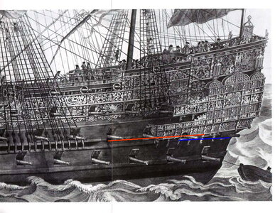
Nope... deck must be continuous!
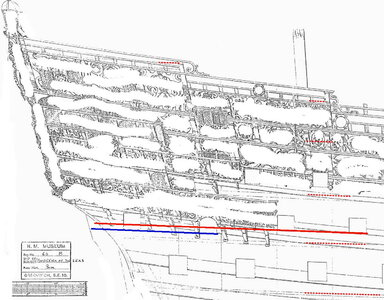
Here's where the ports should be moved to, THEN place the side galleries where they need to go.
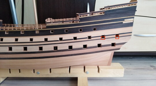
Another point: See how the lower gun deck ports and almost underneath the guns of the uppermost gun deck? Bad construction. The guns are best distributed so that they do not line up vertically with each other. even across multiple decks. The support structure of decks, beams, and stanchions would be more stress if guns added their cumulative weights to one area.
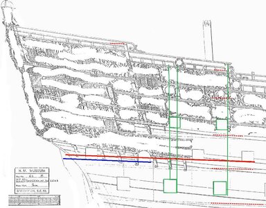
See the gun port alignment in green below. This is how the guns should be aligned, to distribute their weight as evenly to the supports as possible.
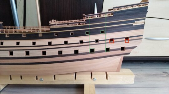
Last edited:
I have been following along with your build so I know there are questions about gun ports that drop below the 'known' deck position. I think my comment finds it's origin in this: wouldn't the decks be parallel with one another (wouldn't the headroom be the same at both ends of the ship)? Perhaps it's parallax caused by camera position or from the curvature of the hull - but to my eye the vertical space between the upper row of gun ports and the middle row of gun ports increases as you move from fore to aft. If this is your intent then just ignore me - you know far more about your ship than I do (EPIC UNDERSTATEMENT) - but I had to ask. Patching and re-cutting gun ports later would not be fun! The orthodontist in me sees 'lines' and 'symmetry' and something just looks off.I believe that sudden downward placement of the last two gun middle gun ports on each side at the stern is one of the mysteries involving this model. I mentioned this in post #230 earlier. Payne and Willem Van de Welde both show those two gun ports on the end seemingly a meter or two below where you think the gun deck would be if you are following the sheer lines (planks and side galleries) of the vessel. However, we know that HMS Sovereign of the Seas was required to have three continuous, uninterrupted flush gun decks below the castles. There is a long discussion on the MSW forum about this. Frank Fox, an expert in 17th century vessels, said that the gun port do not follow the sheer lines of the hull, they follow the overall hull shape, the curvature of which is much flatter than the sheer lines. So, even though the planks run along this deep curve, the hull does not. When you see the lines of guns and the slant of the planks and side galleries together, the gun ports don't line up elegantly. The line of ports seems almost flat, even though there is some curve. I believe that artists drawing the lines of ports have to be regarded with caution regarding gun port placement. I would not trust their accuracy in this particular feature, any more than I would trust the sheer curve of the banana shaped ships with ridiculously high stern castles in the old paintings. You have to be critical when taking elements from art and applying them to a realistic model. Some features you trust, others you don't. Also, you can't use the design of Wasa for clues in features of English ship building, although it is tempting because the Wasa survived and we have it as a living example of an early 17th century ship. The Wasa was mostly Dutch inspired in construction, but the English have their own way of building ships... because they're English.
So what do I do with those confusing gun ports? I do not think they should "run downhill" as you approach the stern. Logic tells me the best thing to do is position the deck for these guns as an extrapolation of the middle gun deck, and adjust the side galleries such that they are where they appear to be in the paintings/woodcuts relative to the guns. The gun decks as viewed from the side should line up with the stern chaser gun placement just just. A modeler on MSW already figured that out and came up with a computer generated model using Blender 3-D that shows this. The proportions and shape of my model may look a little different than the artists' conceptions, but it will probably be a more realistic representation of a working ship.
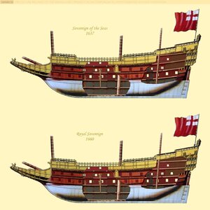
Decks parallel? Not necessarily in a 17th century ship, ESPECIALLY in the stern castle! Look at the 1636 version of the ship below. The decks diverge slightly as you go aft. This ship was rebuild four times, 1650, 1651, 1659-1660, 1685. Major changes were made. It's very hard for me to build the 1636 version because most artists made depictions after the 1659-1660 rebuild, sometimes with a mix of features which were part of the original build but were later removed or replaced! Talk about confusing sources...I have been following along with your build so I know there are questions about gun ports that drop below the 'known' deck position. I think my comment finds it's origin in this: wouldn't the decks be parallel with one another (wouldn't the headroom be the same at both ends of the ship)? Perhaps it's parallax caused by camera position or from the curvature of the hull - but to my eye the vertical space between the upper row of gun ports and the middle row of gun ports increases as you move from fore to aft. If this is your intent then just ignore me - you know far more about your ship than I do (EPIC UNDERSTATEMENT) - but I had to ask. Patching and re-cutting gun ports later would not be fun! The orthodontist in me sees 'lines' and 'symmetry' and something just looks off.
Here are some decent representations of where the decks were in HMS Sovereign of the Seas. The accuracy of the following images in other details is debatable, but the changes in deck arrangement are pretty well represented.
After 1660 rebuild:

As built in 1636 versus after the 1660 rebuild where decks were repositioned:
(Sorry Sakhalia.net... I'm a pirate!)

Kurt,
The level of deep research that you rise to with all your projects is very impressive, especially with this one. Big cheers learning so much as well.
Cheers,
The level of deep research that you rise to with all your projects is very impressive, especially with this one. Big cheers learning so much as well.
Cheers,
What can I say, John? I'm a glutton for information when I work on a project. I like to gather as much as I can before making the next step because it's hard to get a model ship accurate, or many times even half right. It's part of the work, and you change your mind when new information is found. How many model makers were disappointed when they learned their blue models of Wasa were supposed to red instead? We all try to get he best information we can, or we can just skip the research and make it easier by building models of ships that never existed like the Black Pearl or San Felipe.Kurt,
The level of deep research that you rise to with all your projects is very impressive, especially with this one. Big cheers learning so much as well.
Cheers,
Last edited:
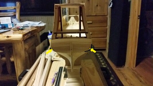
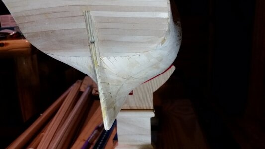
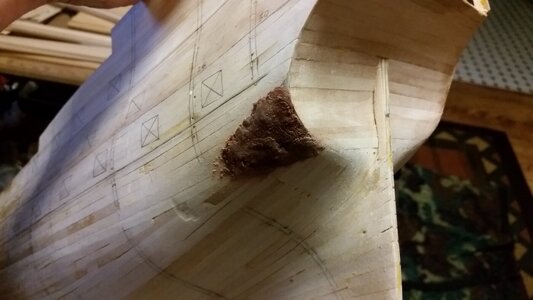
The stern on the DeAgostini model has a fat butt. It's far too wide in the lower stern. This particular feature has been bothering me for a month. The bottom of the stern should be round, not egg shaped at the widest points. So, out comes the belt sander for some weight reduction! Some of the planking was sanded through, but that was fixed with filler. After sanding, the shape looked a bit more like the the ship in the Portrait of Peter Pett, although it is still not a perfect match in shape. After sanding, the filler and even the edge of the frame in one spot is showing. A thin layer of PVA toughens up the surface of the filler.
Sand the bulges on lower stern sides to meet the pencil lines, shown by the arrows.
New curve is more round and gentle, not sharp. This makes the stern appear more round over.
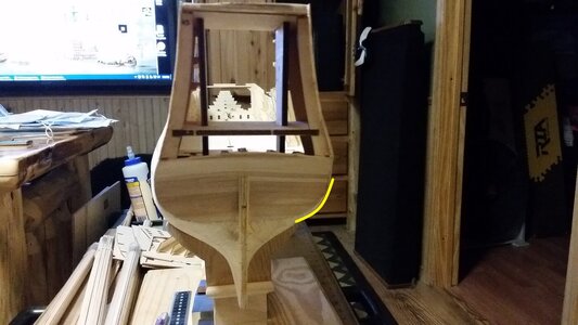
The tuck is looking a bit better, as are the side curves of the stern.
Application of filler to the depressions and holes
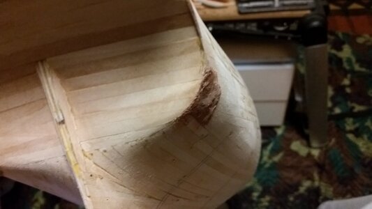
After sanding with a rough sanding block.
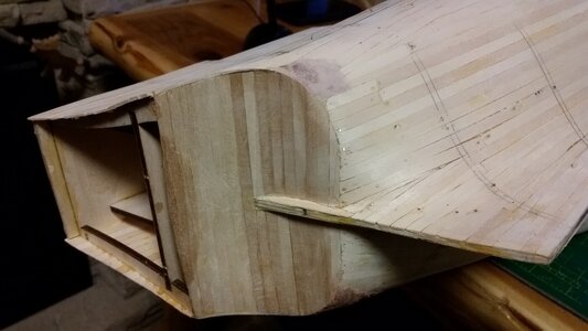
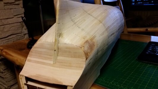
Sand the bulges on lower stern sides to meet the pencil lines, shown by the arrows.

New curve is more round and gentle, not sharp. This makes the stern appear more round over.

The tuck is looking a bit better, as are the side curves of the stern.

Application of filler to the depressions and holes


After sanding with a rough sanding block.


In a lot of 17th century ships the deck at the aft two gun ports is dropped or is showing a knick. Two reasons for this are 1 the rudder tiller is entering the ship so more room is needed for the tiller and the rudder boom (Kolderstok in Dutch).I have been following along with your build so I know there are questions about gun ports that drop below the 'known' deck position. I think my comment finds it's origin in this: wouldn't the decks be parallel with one another (wouldn't the headroom be the same at both ends of the ship)? Perhaps it's parallax caused by camera position or from the curvature of the hull - but to my eye the vertical space between the upper row of gun ports and the middle row of gun ports increases as you move from fore to aft. If this is your intent then just ignore me - you know far more about your ship than I do (EPIC UNDERSTATEMENT) - but I had to ask. Patching and re-cutting gun ports later would not be fun! The orthodontist in me sees 'lines' and 'symmetry' and something just looks off.
But the second reason which is more important is that the gun cariages for the stern chase ports were taken from the gun ports in the brought side. These were turned and pushed to the stern. If you would do this at a deck which is rising to the stern this would be a difficult task. A flat deck is therefore necessary. During the end of the 17th century the decks became more flat and the deck drop, knick was cancelled.
So, the question is then, does the deck change angle near the stern end, flattening out to position the last two sets of guns to be a bit lower, in order to make room for the rudder tiller and whipstaff and still allowing the deck to be "flush"? Dutch and English ship construction is different, so it's hard to make a conclusion here.In a lot of 17th century ships the deck at the aft two gun ports is dropped or is showing a knick. Two reasons for this are 1 the rudder tiller is entering the ship so more room is needed for the tiller and the rudder boom (Kolderstok in Dutch).
But the second reason which is more important is that the gun cariages for the stern chase ports were taken from the gun ports in the brought side. These were turned and pushed to the stern. If you would do this at a deck which is rising to the stern this would be a difficult task. A flat deck is therefore necessary. During the end of the 17th century the decks became more flat and the deck drop, knick was cancelled.
Kurt,
I was going through images of Doris' SotS - you must certainly know of her - Not arguably !, but THE best work in the world - anyway here is a link to the 1000s of images from her Sovereign - (at the bottom of each page it leads to the next page and so on.....
Members, if you DON'T know about her work - caution you will spend hours marveling at what seems impossible in this hobby to actually create. BTW every gold gilded piece was also created by hand. Her other ships are just as shockingly amazing - AND when she also creates the interiors - it's even more astonishing.
PS: I now need to rethink the beakshead for my current build YIKES lol -
Yours is coming along very nicely - the hull gun openings are indeed a bit odd on this one, aren't they?
Cheers,
After mowing the lawn, I had a few hours left to start planning the construction of the lower gun deck. First, some of the cannon ports were adjusted in position to make for sense from a structural support sense (avoid ports overlapping each other vertically where possible). The entry port on the port side was also shifted aft so the position closer resembles the Payne and Willem van de Velde illustrations. I'm convinced that model kit makers tend to design the positions of the frames to create the hull shape first, and let the gun ports fall wherever they don't intersect the frames, making the ports occasionally line end up where they shouldn't be.
Strips of basswood were shaped to make lower gun deck supports that have camber. They are shown near their final positions and are not glued down. Plotting the locations for hatches, capstans, and other deck openings like companionways will be done first, and each opening will be framed in basswood before the deck is laid down. Deck supports will be shifted to accommodate the deck openings. The deck will be thin strips of Tanganyika wood, the same that is typically used on many model decks, but they will have to be attached to a thin veneer in sections and laid side by side on the cambered deck support and hatch and companionway frames.
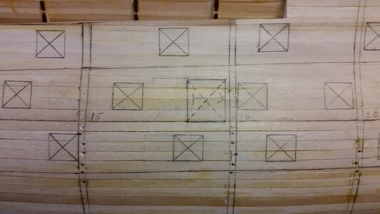
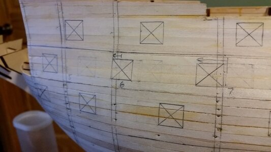
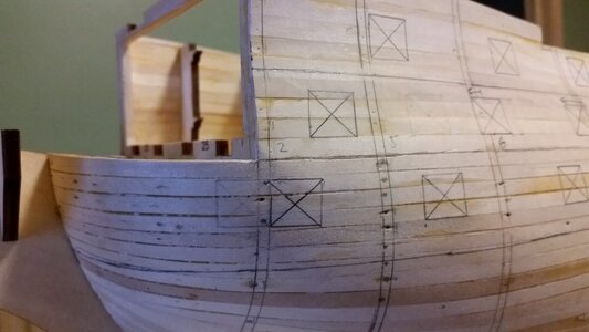
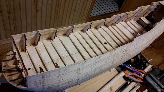
Strips of basswood were shaped to make lower gun deck supports that have camber. They are shown near their final positions and are not glued down. Plotting the locations for hatches, capstans, and other deck openings like companionways will be done first, and each opening will be framed in basswood before the deck is laid down. Deck supports will be shifted to accommodate the deck openings. The deck will be thin strips of Tanganyika wood, the same that is typically used on many model decks, but they will have to be attached to a thin veneer in sections and laid side by side on the cambered deck support and hatch and companionway frames.


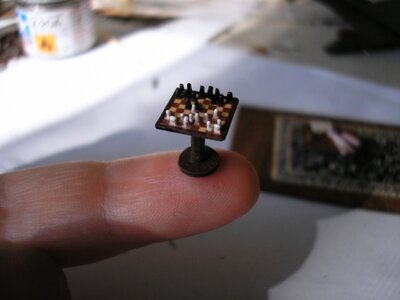
I've known of her work for a few years. I downloaded ALL her pictures one HMS Sovereign of the Seas, back when I was starting to build La Couronne, because my goal was to build SotS when I got into building these models. Did you see the chess board she made for the gallery?Kurt,
I was going through images of Doris' SotS - you must certainly know of her - Not arguably !, but THE best work in the world - anyway here is a link to the 1000s of images from her Sovereign - (at the bottom of each page it leads to the next page and so on.....
Members, if you DON'T know about her work - caution you will spend hours marveling at what seems impossible in this hobby to actually create. BTW every gold gilded piece was also created by hand. Her other ships are just as shockingly amazing - AND when she also creates the interiors - it's even more astonishing.
PS: I now need to rethink the beakshead for my current build YIKES lol -
Yours is coming along very nicely - the hull gun openings are indeed a bit odd on this one, aren't they?
Cheers,

Last edited:
Agree with you here, there are contradictionary contemporary sources so we will never know for sure.So, the question is then, does the deck change angle near the stern end, flattening out to position the last two sets of guns to be a bit lower, in order to make room for the rudder tiller and whipstaff and still allowing the deck to be "flush"? Dutch and English ship construction is different, so it's hard to make a conclusion here.
Pick the best one to suit your solution.
Now its getting exciting. Entering uncharted waters!After mowing the lawn, I had a few hours left to start planning the construction of the lower gun deck. First, some of the cannon ports were adjusted in position to make for sense from a structural support sense (avoid ports overlapping each other vertically where possible). The entry port on the port side was also shifted aft so the position closer resembles the Payne and Willem van de Velde illustrations. I'm convinced that model kit makers tend to design the positions of the frames to create the hull shape first, and let the gun ports fall wherever they don't intersect the frames, making the ports occasionally line end up where they shouldn't be.
Strips of basswood were shaped to make lower gun deck supports that have camber. They are shown near their final positions and are not glued down. Plotting the locations for hatches, capstans, and other deck openings like companionways will be done first, and each opening will be framed in basswood before the deck is laid down. Deck supports will be shifted to accommodate the deck openings. The deck will be thin strips of Tanganyika wood, the same that is typically used on many model decks, but they will have to be attached to a thin veneer in sections and laid side by side on the cambered deck support and hatch and companionway frames.
View attachment 236049
View attachment 236050
View attachment 236051
View attachment 236048
Yup. From here on out it's mostly scratch building.Now its getting exciting. Entering uncharted waters!
Scratch building does indeed have it's + side, adding a nice building challenge. That said - this is where tools become SO important in this hobby.
+1. Good tools are necessary for good scratch building, although you can do a LOT with a saw, some files, and a sanding block.Scratch building does indeed have it's + side, adding a nice building challenge. That said - this is where tools become SO important in this hobby.
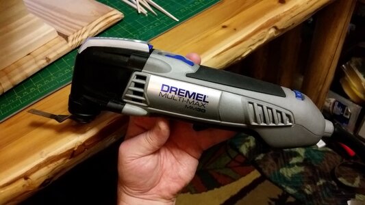
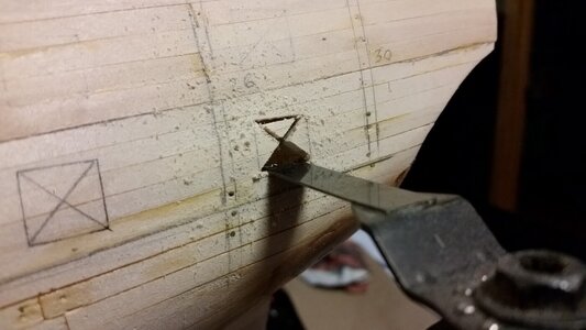
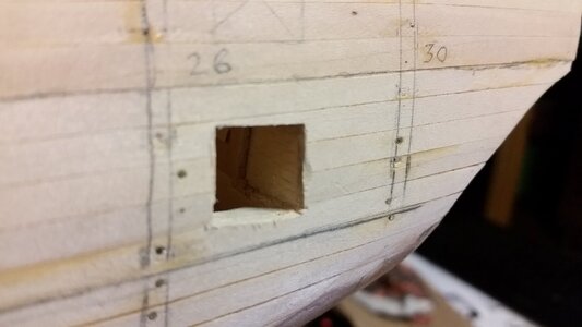
The gun port positions on the side as positioned by the DeAgostini instructions conflict strongly with the stern gun port positions, if one is trying to keep the stern guns on the same flush deck as the lower gun deck and upper gun deck gun ports and viewed from the side. Just like Uwe did, I am considering reshaping the curve of the lower counter to make the arc less deep before trying to plot the stern gun ports again. The last gun port on the lower gun deck, port and starboard, was test cut using a Dremel Oscillating saw. The worked great, cutting a perfect 13mm slot at the top and bottom of each gun port, and the "X" in the center. The rest was removed with a razor knife. But then I decided the gun port had to move down 3mm, recut he ports, and filled the upper portion of the port with wood. The was done after re-evaluating where the deck line at the stern should be and re-drawing it on hull, making the line a bit flatter in an attempt to line it up with the lower stern chaser gun ports. Still, the alignment is not satisfactory.
Planning of the lower gun deck details was started. Using McKay as a reference, the capstan and grating locations were plotted, and the grating holes cut through the deck. I will probably not use McKay's layout of the ladders, and will research other ladder location designs before making a final choice where to put them. It would be nice to have some reliable sources to draw upon for this, but I don't think any exist.
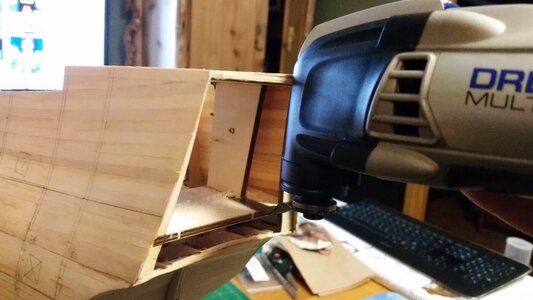
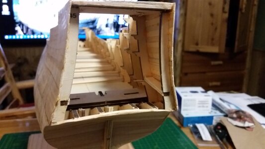
First major support removed from the stern castle. More to follow later.
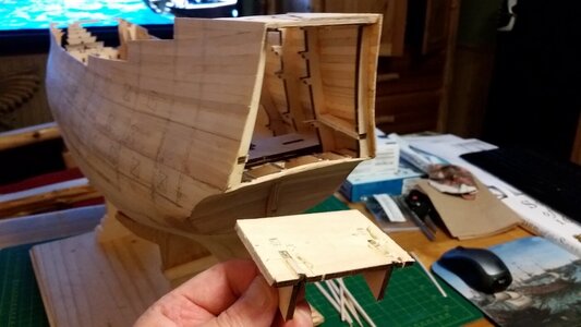
This tool is great. It does demolition of interior supports and cuts gun ports with precision. The plunge cut is precisely 13mm wide.
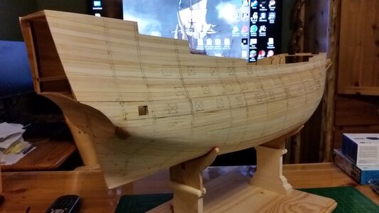
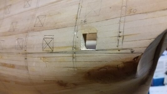
Gun Ports are too high and need to be repositioned, but they don't line up with the lower gun deck.
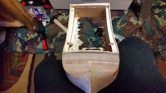
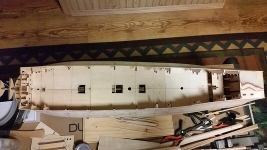
Planning of the lower gun deck details was started. Using McKay as a reference, the capstan and grating locations were plotted, and the grating holes cut through the deck. I will probably not use McKay's layout of the ladders, and will research other ladder location designs before making a final choice where to put them. It would be nice to have some reliable sources to draw upon for this, but I don't think any exist.

First major support removed from the stern castle. More to follow later.

This tool is great. It does demolition of interior supports and cuts gun ports with precision. The plunge cut is precisely 13mm wide.


Gun Ports are too high and need to be repositioned, but they don't line up with the lower gun deck.


Last edited:
Very interesting posts and information - great to follow!!
Kurt,
You have really captured the profile, hull lines and deck widths - excellent difficult start - looking very good. I will be also very interested to see how you plan on detailing the upper deck inner bulkheads. Early drawings indicate some curved shapes. McKay's image for the inner forecastle deck bulkhead is flat with two large doors (I plan on mirroring that look) not sure if it is historically correct - Your level of research is light years ahead of mine.
Very much enjoying following and learning from your current log.
Regards,


