HMS Sovereign of the Seas - Bashing DeAgostini Beyond Believable Boundaries

Kurt,
You have really captured the profile, hull lines and deck widths - excellent difficult start - looking very good. I will be also very interested to see how you plan on detailing the upper deck inner bulkheads. Early drawings indicate some curved shapes. McKay's image for the inner forecastle deck bulkhead is flat with two large doors (I plan on mirroring that look) not sure if it is historically correct - Your level of research is light years ahead of mine.

Very much enjoying following and learning from your current log.

Regards,
I'm just gathering all the sources I can, verifying them with learned advice from those who have long studied ships of this time (when available), studying other model builder's examples, then ranking possible alternative features from probably realistic to utter fantasy, then choosing which features appear to be the most accurate from what information there is. Then you take the next step in construction of your model. I may miss a good source or two, and I wish I had the background of someone like Frank Fox or James Sephton, who specialize in 17th century ship design. I have saved all of Mr. Fox's comments on MSW forum regarding the Sovereign for reference, and there is a wealth of information there. However, if you do enough searching, most of the features that are in doubt can be decided upon. Where no information on a feature is found, and there are no similar examples to draw from on other ships, you have to take your best guess. What I should do at this early stage is chronicle the changes I am making in detail to the DeAgostini model so others can see what was changed, and decide for themselves if the same changes should be incorporated in their model. That way, they don't have to reinvent the wheel. I'll start by logging the location changes to the gun ports.

The height of the lower gun deck is as it was set by the DeAgostini model design. Gun port location changes to the middle and upper gun decks will determine where vertical location of the those decks will be constructed. Since the stern is to be gutted, an extension of the lower gun deck will have to be created, like it was done in the model of La Couronne. Otherwise there will be nothing for the cannon carriages to rest on. Since the shape of the hull was largely determined by DeAgostini, minor changed to the shape are all that will be allowed to complete this model. Otherwise, if large changes are required, it would be better to start with a new hull from scratch. My changes won't make it perfect, but it will be an improvement. None of the model makers I've seen get it all correct with regard to the hull and deck design, so everyone needs to modify their model to some degree to make it more accurate. Don't even get me started on the McKay design. So far I've found errors in his capstan design, which capstan he illustrates using with the messenger line, accommodation ladder placement interference with the rear capstan, and a host of other obvious problems that even a modern marine engineer like myself can pick out without conferring with a wooden ship historian. It is dangerous NOT to challenge all of the internal ship features of McKay's design and verify them with other sources, not if you care about placing internals in your model.

So far, my study of the lower gun deck will force me to move the rearmost gun port locations once again, lowering them until they actually do appear in a straight and level live above the water, just as in Payne and Van de Velde's depictions. This will allow the stern chasers to be lowered on my model to their correct positions, low on the counter.

To answer your comment about what features will be incorporated on the interior decks, certain features will be made, others left out. The problem is that you will not be able to see most of them through the narrow spaces offered by the gun ports. Many details would never be seen without a borescope. I am debating whether or not to include breeching ropes and gun tackles on the carriages of the middle and lower gun decks, since they present a huge amount of work and may not be visible later, even if the interior is illuminated. Such details are necessary in half hull models, but not in fully rigged whole models. Suggestions on what details to place in the interior are welcome. It would be nice to be able to furnish the gallery spaces and cabins which are furnished with portals. Doris had the advantage of working on a larger sized model that 1:84 scale, which places more limitations on detail. As for bulkhead shape, that will have to be researched before constructing. If you have any sources besides McKay (yuck!), let me know. I have detailed photos of Doris's bulkhead locations and shape from her construction photos. And if any of you fellow builders have comments on construction details offered by James Sephton in his book, please let me know. I already noted the Sephton and McKay both cite a cannon of VII as having a projectile weight of 60 pounds, where Frank Fox stated that it should be 42 pounds. These bits of information are important.
 
Last edited:
Well Kurt,
We live in diff. worlds - I'm overwhelmingly impressed with your astonishing level of acquired knowledge sources as you progress with your current project - big kudos for you . I stand (sit) humbled - this image taken from your address link Thumbsup--- closes the case.
Humbled indeed lol........

030-Place-All-Instruction-Magazines-in-Binders.jpeg
 
Well Kurt,
We live in diff. worlds - I'm overwhelmingly impressed with your astonishing level of acquired knowledge sources as you progress with your current project - big kudos for you . I stand (sit) humbled - this image taken from your address link Thumbsup--- closes the case.
Humbled indeed lol........
Many thanks, oldflyer. Your comments humble me! You'll find the best source are the guys on this and other forums. Books are great too, but they can get expensive. I'm also following your build of HMS Sovereign of the Seas closely.
 
After much time pondering, measuring, changing things, and pondering some more, the locations of the gun ports and entry portal on the port side have been finalized.

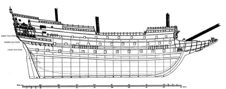
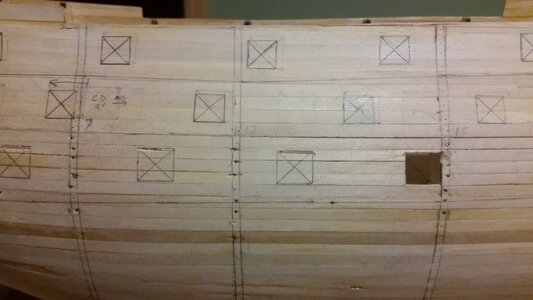
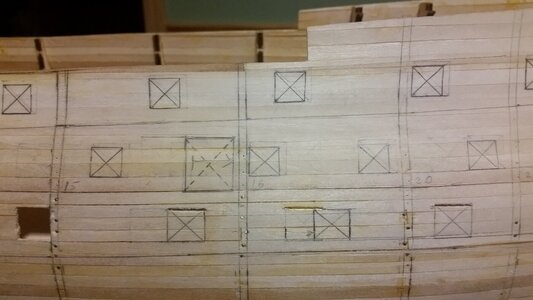
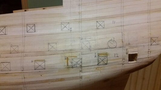
Time to post some stuff. The lower gun deck ports are 13mm wide x 12mm high following the kit instructions (they should be square) and simulate 37"-38" square ports. The middle and upper gun ports are 11.4mm square, and simulate the original 30" square for the middle ports and 28" square for the upper gun ports. The dimensions for the original gun ports, taken from James Sephton's Sovereign of the Seas: The Seventeenth Century Warship, are now better represented on the model. Changes to the size of each port were made such that the forward and bottom edges are unchanged, and the reduction of the port size from what DeAgostini calls for and the new custom size is accomplished by moving the rear and top edges. So, after plotting the ports according to DeAgostini, the size and locations were adjusted. One of the considerations was to move the ports to locations and line-up according to the Payne and Willem van de Velde depictions. Another was to ensure that no two gun ports on any of the three gun decks lined up vertically, because the ship's support structure would be stressed if the weight of two guns were concentrated in one spot. The two aftermost middle and the one aftermost upper deck gun ports, which the DeAgostini instructions did not have you draw on the hull this early in construction, were placed such that they line up on a line formed from the ports nearest midships, drawn straight and level back toward the stern, instead of following the slow ascending curved line that DeAgostini places the ports. This makes the model look more like the Payne depiction, with a level and flat line of gun decks that do not follow the sweeping shear lines of the ship's hull shape, even crossing the wales. It may not appear elegant, but that's how they built these ships. Note also that an extra port was added to the lower gun deck near (just abaft) of the beakhead bulkhead. This port was never used, and contained no cannon. According to James Sephton, it was there as an emergency bow chaser, and should have been depicted by Payne to have no gun, because having it so close to the hawse pipes means that the gun would interfere with the handing of the anchor cable inside the ship on the lower deck. Other ships likewise placed no gun here, and later ships deleted the port entirely from this location. To assist fellow DeAgostini kit bashers in making their own modifications, below is a table of the changes made to the port locations.

Modifications to DeAgostini's HMS Sovereign of the Seas Gun Port and Entry Portal Locations and Sizes

Location adjustments of gun ports, counting from bow to stern:
12345678910111213
Upper Gun Deck:
no changeno changeno changeno changeno changeno changeno changeno changeno changedown 2mmno changen/an/a
Middle Gun Deck: (Entry portal moved 15mm aft)
no changeforward 5mmforward 15mmno changeno changeno changeno changeno changeno changeno changeforward 5mm, down 2mmcircular port, follows flat line of gun portsfollows flat line of gun ports
Lower Gun Deck:
New port, behind beakhead bulkhead, no gun (closed port)no changeno changeno changeno changeno changeno changeaft 10mmno changedown 2mmaft 13mm, down 3mmdown 5mmdown 8mm

Gun Port Plan.jpg


The consequences of wanting to fit complete gun carriages on a model designed for fake gun barrels on the lower gun deck are making themselves apparent, causing a few problems. I recently bought a huge pile of laser cut gun carriages for this model from our friend Dave at Lumberyard for Model Shipwrights, and now it was time to start figuring out how to make them work. They turned out to be from a later time period, resulting in carriages that are too long for my gun barrels. Also, the gun ports are located low with respect to the flat deck of the DeAgostini model, and that combined with the high vertical height or Dave's carriages has presented a problem. I tried using one of the DeAgostini provided carriages, and the muzzle was low enough to stick out of the port, but the DeAgostini carriages are nowhere close to accurate. Add to this the extra thickness to the deck about to be laid over the flat plywood deck, and the problem worsens.

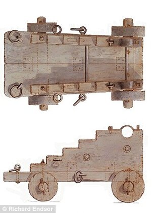
So, I have a plan. If I take Dave's carriages, and cut 1/4" off the front end, they become short enough to better fit the barrels. Then, I cut some wood off the bottom and redesign the carriage to look a 17th century English carriage like this:

Deck Cannon Carriage Design 2.jpg

That carriage was from the 1650's but it's the closest design to the 1630's that I can find. Now, do this 24 times, and the length and height should be adjusted just enough to get the gun barrels to protrude from the ports at the correct height even with the added camber and planking to the deck. The carriages for the tow decks of guns above, which are lighter, may be made a bit different in height because the vertical locations of the middle and upper gun decks will not rely upon the DeAgonstini hull framework and can be placed where you want them to go. For the carriages on the lower gun deck, I will make some jigs to cut the carriage parts consistently using the band saw. The carriage parts are so precise that modifying them will be easy, and the wood is excellent, so no splintering or cracks should occur if I'm careful. Add a tapered bottom member to each carriage, some custom eyebolts and rings, and the carriages will be perfect. Train tackles are not necessary, nor historically supported, so that saves a lot of work on rigging them.

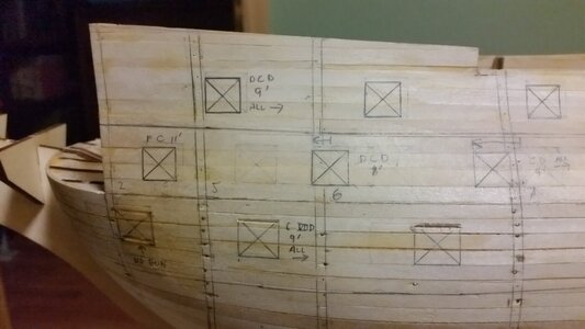
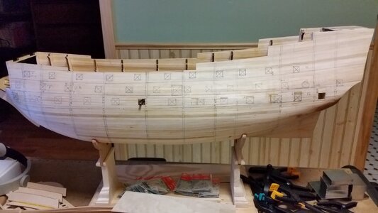
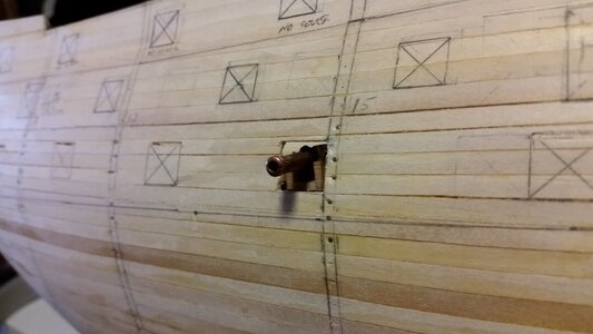
Here are pictures of the new port locations and sizes. All the pencil erasers show every mistake and change, including some cuts in the hull that are now in the wrong places and some filled in areas of the hull. All these marking and mistakes will be covered up. Some notes also appear to indicate the type of guns to be installed, but these notes are incomplete: "FC 11'" for "fortified culverin 11' long" and "DCD 9' all -->" for "demi culverin drake 9' long, the rest of the guns on this deck all the same". "C VII D 9'" is a "cannon of VII drake, 9' long". The gun lengths are not set in stone, and vary +/- several inches depending on your information source, but the lengths are generally accurate. Just like on the model of La Couronne, various sizes of gun barrels will be used, instead of the "one size fits all" barrels most kits provide.
237 Gun Port Adjustments 1.jpg

238 Gun Port Adjustments 2.jpg

The entry portal was moved aft to the location it appears in Payne's depiction.
239 Gun Port Adjustments 3.jpg

A deck will need to be fabricated for gun port 13 on the lower deck to support the gun carriages, after more interior supports are removed.
340 Gun Port Adjustments 4.jpg

The gun at midships rests on a DeAgostini carriage, which is very low. Custom carriages need to be made for all guns. Having all the gun ports plotted is a major milestone is research for this ship. It will determine the location of the deck elevations within. As decks are built from the bottom up, sections of the existing upper hull frames will be demolished and removed, hopefully not disturbing the shape of the planking skin.
341 Looks Good So Far 3.jpg

Dave's 18th century carriage from the Lumberyard on left is actually for a 1:48 6 pound gun. The DeAgostini kit carriage is on the right. Each is bearing a 9' long (36mm) cannon of VII drake, the largest guns on HMS Sovereign of the Seas. The boxy DeAgostini carriage is not historically accurate.
342 Cannon Carriages, Ship Model Lumberyard (L) and DeAgostini (R).jpg

The sun was shining on my French man of war La Couronne today, a most positive omen.
236 La Couronne in the Sunline.jpg
 
Last edited:
If anyone on the forum knows of any features or points which the authors and historical sources got something wrong, please tell be so I don't use that feature in the model. For example, Payne depicts a gun barrel in the forward most port, near the anchor cable hawse ports, which is contrary to what is known for other English men of war. Those having such a port on each side of the hull left it vacant because the gun carriages interfered with anchor cable access while raising anchor.
Yes one of the issues that I had with Sergal using their lower gun deck template as a guide, and my cutting the rounded forward bulkhead to a flat face made matters worse in that it will move that bulkhead facing a bit rearwords after I build and install its face. I think that I will, as you suggest for your build, just close those two gun port lid doors.

As Paul just posted above --- indeed true.

PS: I just Amazon downloaded into my iPad James Sephton's Sovereign of the Seas: The Seventeenth Century Warship -- had thought of it before, now done. Reviews are not very positive, but certainly lots of technical information of great use. For me it was the apparent addition of several images near end of book (per one of the reviews) - have not opened it yet.

Your log will be THE go to reference for any builder of this ship. Thumbsup
 
Heh.. we'll see! Your Wasa set the bar pretty darn high. At the level of detail we are both working at, there's no way I'll catch up with you now. May rigging will slow you down...
Ha! Learning how to rig will slow me down before rigging slows me down. I keep adding inconsequential details to my build as I obsess over pictures from the museum ship. @oldflyer was a victim of this as well based on his Vasa build...

Plus, I recently ordered a rope walk. Plan right now is to make my own ropes if I can figure out how to make it work and how to create scaled rope sizes from it...
 
Yes one of the issues that I had with Sergal using their lower gun deck template as a guide, and my cutting the rounded forward bulkhead to a flat face made matters worse in that it will move that bulkhead facing a bit rearwords after I build and install its face. I think that I will, as you suggest for your build, just close those two gun port lid doors.

As Paul just posted above --- indeed true.

PS: I just Amazon downloaded into my iPad James Sephton's Sovereign of the Seas: The Seventeenth Century Warship -- had thought of it before, now done. Reviews are not very positive, but certainly lots of technical information of great use. For me it was the apparent addition of several images near end of book (per one of the reviews) - have not opened it yet.

Your log will be THE go to reference for any builder of this ship. Thumbsup
There are no guns on those first two ports at the bow, so just leave the ports closed. I'm sure that's what the original ship did. Willem van de Velde showed ports closed. At present, those ports on my model are just behind the forward bulkhead, and I may move them a bit more forward to match what the Payne and van de Velde depictions look like. Like you said, if the ports are closed, you wont have to worry about interference between the frame on the model that is integral with the bulkhead and a cannon carriage inside, because there is no cannon. Sephton has a ton of great details. I'm not sure where he gets the specifics such as the size and location of gun ports that he chooses, although he referenced how some other modelers made them. You certainly don't get those sorts of details in other sources, unless you trust the assumptions that McKay makes. Speaking of McKay, I just obtained a copy of Sir Anthony Deane's Doctrine of Naval Architecture, 1670. I am still trying to figure out why McKay uses this as his primary source for ship design details for the Sovereign, excluding what Peter Pett wrote in some cases. Maybe he just likes the author. Deane's book is mathematically detailed for how hull shape is determined, but to assume that the Sovereign utilized these rules to the letter if quite a stretch considering that the ship was designed almost 50 years previously by a separate ship designer, and the fact that the Sovereign of the Seas was unique in design for the times (basically a prototype for a large man of war) probably means that by the time Deane wrote his doctrine, some significant changes would have been made. The model T Ford wasn't fuel injected....

There are some differences in the hull shapes and superstructures between the Mantua/Sergal SotS and the Deagostini. Each need to be modified to fit our latest research sources It's good to compare the two when deciding where to place ladders, gratings and deck equipment, but both models are interpretations, and the research sources we can draw upon with books and the internet are now probably greater and more varied than the kit companies used when they designed thier models. Forums like this are a gold mine for locating new research sources. So, any new guys to modelling shouldn't be afraid to change things if the changes make sense, and you trust one of your sources more than the kit instructions.
 
Last edited:
...I keep adding inconsequential details to my build as I obsess over pictures from the museum ship. @oldflyer was a victim of this as well based on his Vasa build...

Plus, I recently ordered a rope walk. Plan right now is to make my own ropes if I can figure out how to make it work and how to create scaled rope sizes from it...
Hah. Welcome to scratch building. I'm in the same position. You think you'll just build a kit and admire it. Then you add stuff, and when it's done, it looks incredible, certainly nothing like what's on the box art!
 
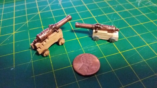
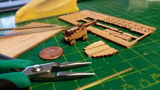
I took a test subject, one original Dave's Lumberyard for Shipwrights cannon carriage, and twisted it to my evil purposes.

Here we have an innocent, 19th century carriage, about to undergo a metamorphosis that will transform it into a carriage from two hundred years previous. The cannon barrel will be moved to the location as shown below, and the front of the carriage cut shorter.
243 Carriage Before Modification.jpg

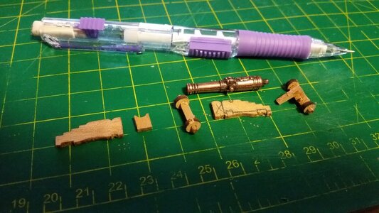
The little carriage resisted attempts to dismember it, screaming violently as the razor knife rendered it back into its essential parts. Note the markings on the side plate showing where the cuts will be made.
244 Carriage Redesign Planning.jpg

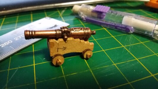
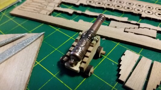
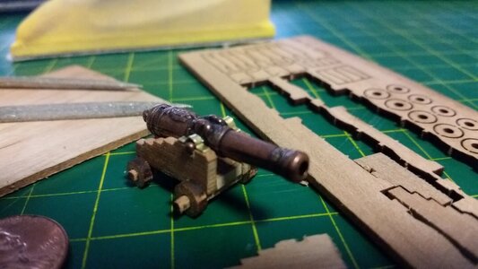
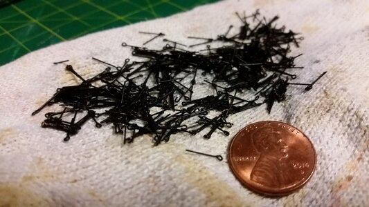
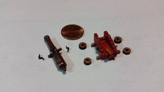
The extra wood attached to the laser cut cannons Dave provided was excellent material from which to make the floor pieces for each carriage. A tapered floor piece was cut on the band saw, and the side pieces (cheeks) have been trimmed off at the front and bottom edges. The front and rear axletrees were reattached. Lots more work can be done to finish this carriage. Scratch built capsquares, which hold the trunnions to the cheeks, were made from brass strip. They will be blackened later, and the carriage painted. The axle hubs should be trimmed, and I debated adding iron gun tackle and train tackle loop, but they probably won't be visible on the lower decks. The visible gun carriages on the open decks will be lavishly detailed.
245 Carriage After Modifications.jpg

246 Older Style Carriage.jpg

A mid 19th century English carriage transformed into a late 17th century carriage.
247 Older Style Carriage.jpg

A problem remains in that when the deck is installed, the guns will be positioned too high with respect to the gun ports. Below, the gun carriage is lifted slightly by a thin plywood sheet laying on the camber shaped beams I made earlier. For the lower deck, it appears that it may have to remain flat in order for the guns to be in the proper vertical positions. The only option is demolishing the deck and starting over, or chopping the bottoms of the trucks (wheels), which would look horrible.
248 Better Fit but Barrel Still Needs to be Lower.jpg
 
Last edited:
Maybe you can reduce the side height of the carriage a little of course on both sides. Trim off about 1 or 2 mm near the truck and not the trunnions side.
 
Maybe a stupid idea, but easy to make and I think it could work and will be not visible.
You could flatten the front wheels, like a "flat tire" - just an idea
 
Maybe a stupid idea, but easy to make and I think it could work and will be not visible.
You could flatten the front wheels, like a "flat tire" - just an idea
Thanks. Yes, I thought of that too. That is a last resort. I'm trying to make the deck as thin as possible, so as to keep it lower. That and a combination of filing flat spots on the front trucks of each carriage may be the solution.
 
Maybe you can reduce the side height of the carriage a little of course on both sides. Trim off about 1 or 2 mm near the truck and not the trunnions side.
Working on several ways to lower the deck by making it thinner near the bulwarks or the front trucks of each carriage. a combination of techniques may do the trick without looking obvious.
 
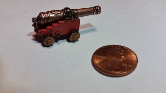
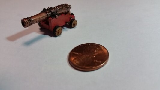
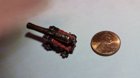
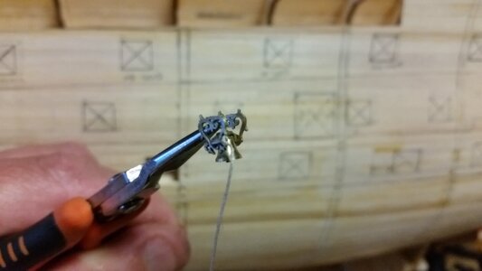
More work on the cannon carriage. The transom, the piece that is located above the front axle and between the cheeks, was installed on the carriage. Tiny eyebolts bought separately were blackened, and tiny rings were split by bending, then passed through four of the eyebolts and bent back to make rings for the breeching lines and train tackle rings at the back of the carriage at the corners. The capsquares, made from a length of formed brass strip, where blackened and glued to the top of the cheeks, over the barrel trunnions.

Now I have to so this 101 more times...

249 Blackened Some Eyebolts.jpg

250 Carriage Painted and Added Eyebolts and Rings.jpg

251 Completed Cannon of VII Drake.jpg


252 Completed Cannon of VII Drake.jpg

253 Completed Cannon of VII Drake.jpg

I found an old locomotive bell at the hobby store that I assembled and will use as the ship's bell up on rear side of the forecastle. Nice find.

254 Locomotive Bell to be Used for Ship's Bell.jpg
 
Hey Doc, while we are waiting for Kurt to respond on his method, I would like to share mine. I think the most crucial part of any type of blackening is a very clean surface.
  • I really recommend using something like isopropyl alcohol, methyl ethyl ketone (MEK), Clean the brass\metal thoroughly with a degreaser and remove any rust. Make sure there’s no residue left on the metal. If this is a rod or tube, first use emery paper or steelwool 1000 grit to remove the top layer.
  • Fabricated parts submerge in the vinegar for a few hours. Rinse with cold water
  • I prefer the 'Brass black' solution. Delute it with water 50/50. Actually, you will need to experiment the amount of blackened solution and water. 50/50 works well for me.
  • The time your parts should take the 'blakened'bath is also experimental. I usually leave them for 10 minutes and check. Also take a soft painting brash and 'paint' those parts from time to time if blakened color adhere to parts, it most likely will stick to the parts.
  • Rince with cold water and let them completely dry.
 
Yes one of the issues that I had with Sergal using their lower gun deck template as a guide, and my cutting the rounded forward bulkhead to a flat face made matters worse in that it will move that bulkhead facing a bit rearwords after I build and install its face. I think that I will, as you suggest for your build, just close those two gun port lid doors.

As Paul just posted above --- indeed true.

PS: I just Amazon downloaded into my iPad James Sephton's Sovereign of the Seas: The Seventeenth Century Warship -- had thought of it before, now done. Reviews are not very positive, but certainly lots of technical information of great use. For me it was the apparent addition of several images near end of book (per one of the reviews) - have not opened it yet.

Your log will be THE go to reference for any builder of this ship. Thumbsup
I have been reading an learning about the Naval ships build in England during the periord that King Charles I and then King Charles II were on the throne. There are some excellent books on the subject but most appropriate to The Sovereign of the Seas is a book entitles "Sovereign of the Seas 1637" written by John McKay, a profesional sreuctural draughtsman for BC Canada. It offers much details of the build, and decoration of the hull, the masts and all rigging with rope specifications and the ships boats. Published in England by Seaforth Publishing the ISBNs are as follows:
Hardback Book ISBN 978 1 5267 6629 8
ePublication ISBN 978 1 5267 6630 4
Kindle ISBN 978 1 5267 6631 1
I prefer hardback books and bought my copy from Amazon a few days ago.

The drawings of the hull, views of each deck with full interior details, all comapnionways, and much more. Exterior details of all decorations. All masts and yards with fullsized dimentsions, sail plan, and all standing and running rigging. Finally detailed drawings of all armaments and gun carriages are given.
If you are building the Sovereign of the Seas or any other ship of the Line be it 3 decks or even two decks from the early 1600s then this book is most valuable and an excellent read in it's own right.
I hope I have not repeated what others have explained previously, and hope that I am "not teaching granny to suck eggs".
If you are interested in naval ships for the latter part of the 17th Centuray in the reign of Charles II there is another series of books that detail the history and design of these ships primarily two deck third Rate ships of the Line by Richard Endsor.

Derek Payne, Stafford, England
 
Back
Top