-

Win a Free Custom Engraved Brass Coin!!!
As a way to introduce our brass coins to the community, we will raffle off a free coin during the month of August. Follow link ABOVE for instructions for entering.
-

PRE-ORDER SHIPS IN SCALE TODAY!
The beloved Ships in Scale Magazine is back and charting a new course for 2026!
Discover new skills, new techniques, and new inspirations in every issue.
NOTE THAT OUR FIRST ISSUE WILL BE JAN/FEB 2026
You are using an out of date browser. It may not display this or other websites correctly.
You should upgrade or use an alternative browser.
You should upgrade or use an alternative browser.
HMS Sovereign of the Seas - Bashing DeAgostini Beyond Believable Boundaries
- Thread starter DARIVS ARCHITECTVS
- Start date
- Watchers 105
I feel like I wouldn't be a good friend if I didn't ask the big question: still sure you want to fully rig guns on the gun decks? You've probably completed enough tackle now for visible guns...
- Joined
- Jan 9, 2020
- Messages
- 10,566
- Points
- 938

If you keep on telling that to yourself, you may start believing it!Assembled another 20 gun tackles. It's actually more fun than tying ratlines... but not much.
...because. Just because.I feel like I wouldn't be a good friend if I didn't ask the big question: still sure you want to fully rig guns on the gun decks? You've probably completed enough tackle now for visible guns...
The model has to match the title of the build log. I am actually looking into installing borescopes, one on each deck, that you can access with your cell phone via bluetooth and see the decks individually. I know it's overkill, but I HATE the look of cutaway hulls.
I know... scary, huh ?If you keep on telling that to yourself, you may start believing it!
I’m glad I read this. I am waiting For blocks and parts to rig the cannons on my quarter deck and forecastle properly and this will assist me. I made one per instructions but I am going to redo this .CheersToday, since making gun tackles is getting a bit boring, breaching lines on the demi cannon drakes and the pair of cannon of VII drakes for the lower gun deck were started. About half of the guns got breech ropes rigged. Not bad for one evening's work. Repetition is making the process get quite fast.
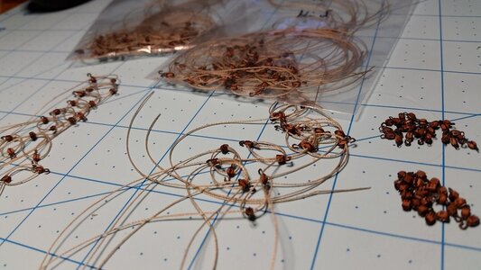
For other novices in modeling, the steps used are detailed as follows. Of course, a magnifying headset and tweezers are required unless you happen to be a human microscope.
1) A 9mm length of 0.8mm diameter is used for the breech rope. for these size carriages, this will place the eyes of the eyebolts just forward of the muzzle of the gun barrel when the breech rope is stretched taut. For speed and simplicity, the line is tied in an overhand knot at the center on the cascabel at the rear of the gun barrel. Typically, the line would be wound with one turn around the cascabel, and seized with small cord to hold it there, but since that cord is practically invisible at this scale, the line was tied and glued instead.
2) Breech rope shown tied and glued with a very small amount of CA glue. In general, CA glue is used in very small quantity and applied to places not easily visible when the gun in complete, so darkening stains will not be visible.
3) Each end of the breech rope is passed through the rings on the side of the carriage and led forward.
4) At the ends of the breach line, the tip of the rope is passed through the ring of a 2mm diameter eyebolt, folded over, then tacked in place with a bit of CA glue, drying by pinching it between your fingers. For additional detail, a black thread is tied around the loop with an overhand knot, secured with a bit of CA glue, then trimmed. This makes the seizing appear very small, thus very close to scale, yet visible because of the contrasting color.
5) Most people stop at this step, but the breech rope does not drape properly over the wheels and hang like real rope, the tan line being rather stiff. To make the entire gun look realistic, this has to be addressed. The breeching rope ends are pulled rearward until the eyes of the eyebolts are positioned just in front of the front edge of the carriage cheeks. To make the rope droop properly, a bit of CA glue (not enough to soak through the line) is placed on the top of the rear wheels and the line is glued there. Then to make the line loops hang down far enough at the rear of the carriage below the casabel, apply some CA glue to the bottom surface of the lines just below the cascabel and hold the line downward until the line stiffens and stays in place. Again, do not use too much CA glue or it will soak through the line and create dark spots. When ready to install the guns on the deck, the the breech rope eyebolts will be glued into holes predrilled in the bulwark, and then tweezers are used to hook the gun tackles to the other eyebolts on the bulwark and to the carriage, then are adjusted to the proper tension.
View attachment 262607
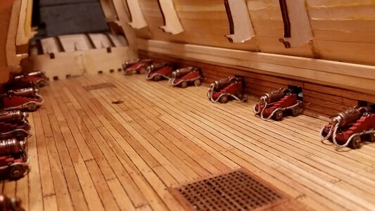
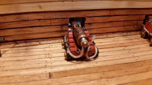
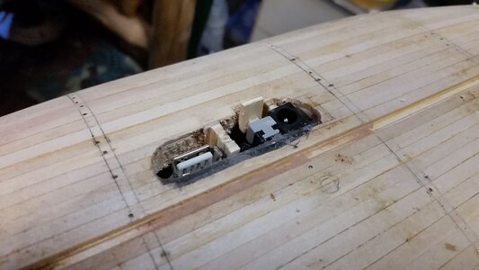
Small steps. A picture was taken of the guns placed on the lower gun deck to see how they look. 1.5mm eyelets were installed in the lower gun deck bulwarks for the gun tackles. Beneath each eyelet is a tiny hole to accept the shank of the eyelet for the breech lines for the carriages. If you look closely, you can spot them. The Arduino Uno electronic circuit board for the three lighting circuits was epoxied in place at the bottom of the hull near the keel. A tab of wood was glue to the on/off switch. The three circuits have a resistor each, and will operate 6 yellow LED's in each circuit at a medium brightness to simulate lanterns.


Looks good Kurt. Forgive me if this was already explained - but you intend to do deck beams and build out a (near) full interior correct? If you can make a camera work that will be so cool to see!
Too keep the deck thin and close to scale, 3mmx3mm beams will be layered on the bottom of a false deck made from 3-ply, 1mm thick smooth plywood. The false deck will have tanganyika planks on the top surface, for the middle deck above.Looks good Kurt. Forgive me if this was already explained - but you intend to do deck beams and build out a (near) full interior correct? If you can make a camera work that will be so cool to see!
1) If I assemble the beam knees and ends of the beams to the bulwarks, using McKay's book as a guide for placement (the only source I have), then the 1mm plywood false deck could be glued on top of this structure of beams, knees and columns in a series of pieces, divided left and right, and from bow to stern. Lastly, the middle gun deck planking can be glued to the false deck. Hopefully the false deck will be in contact with most if not all of the supporting structure without too many gaps. I will be have to be careful not to apply too much pressure on the plywood or risk collapsing the beam structure. One idea is to use a combination of CA and PVA glue. With most of the beams coated with wet PVA glue, several spots will be left bare. CA glue will be applied to these spots, and the plywood held there until it takes hold. This will hold the plywood tight to the support structure until the PVA dries. Or thin pins could be used at various angles to hold the deck ply to the structure. However, pushing pins in may collapse the delicate support structure. Uwe is using this method in his build.
2) Another approach, which takes a lot more careful measurement and fitting, is to attach deck support knees to the bulwarks, place support columns on the gun deck, then glue the beams to the underside of the false deck overhead instead of attaching them at the bulwarks to the knees and to the tops of the columns. The beams would have to be carefully plotted so they do non interfere with the knees, and the joints of the plywood deck pieces will have to be carefully fitted so the beams line up on the underside and there are no wide gaps. Seams would be position over beams to hide them from view underneath, so some beams would support the cut edges of the plywood above them. This method ensures a good bond of the beams to the false deck above.
In both methods, care must be taken to preserve the curvature of the deck in both camber and sheer, not an easy task using method 2). Another thing to watch is the height of the columns, to that the deck overhead contacts the top of each column as evenly as possible. Whatever I do, I want avoid that sickening *CRUNCH* of collapsing deck structure.
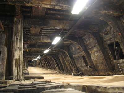
Wasa example, upper gun deck. Note the hanging knees connecting beams to inner side planking, heavy overhead beams and thinner ledges in between the knees, parallel to them. Carlings are the thin, wide boards running across the tops of the beams in perpendicular.
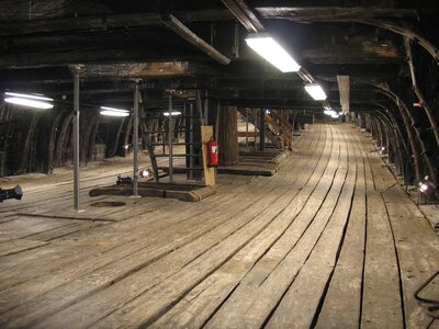
Wasa example, lower gun deck. I can see only one lodging knee, oriented in the horizontal plane, between the beam and the interior planking. It is visible to the right of the closest fluorescent lamp on the right.
Last edited:
Very sharp eyes in the dim illumination even when knowing what you were looking for and found. Great resource photos to guide your progress! Rich (PT-2)Too keep the deck thin and close to scale, 3mmx3mm beams will be layered on the bottom of a false deck made from 3-ply, 1mm thick smooth plywood. The false deck will have tanganyika planks on the top surface, for the middle deck above.
1) If I assemble the beam knees and ends of the beams to the bulwarks, using McKay's book as a guide for placement (the only source I have), then the 1mm plywood false deck could be glued on top of this structure of beams, knees and columns in a series of pieces, divided left and right, and from bow to stern. Lastly, the middle gun deck planking can be glued to the false deck. Hopefully the false deck will be in contact with most if not all of the supporting structure without too many gaps. I will be have to be careful not to apply too much pressure on the plywood or risk collapsing the beam structure. One idea is to use a combination of CA and PVA glue. With most of the beams coated with wet PVA glue, several spots will be left bare. CA glue will be applied to these spots, and the plywood held there until it takes hold. This will hold the plywood tight to the support structure until the PVA dries. Or thin pins could be used at various angles to hold the deck ply to the structure. However, pushing pins in may collapse the delicate support structure. Uwe is using this method in his build.
2) Another approach, which takes a lot more careful measurement and fitting, is to attach deck support knees to the bulwarks, place support columns on the gun deck, then glue the beams to the underside of the false deck overhead instead of attaching them at the bulwarks to the knees and to the tops of the columns. The beams would have to be carefully plotted so they do non interfere with the knees, and the joints of the plywood deck pieces will have to be carefully fitted so the beams line up on the underside and there are no wide gaps. Seams would be position over beams to hide them from view underneath, so some beams would support the cut edges of the plywood above them. This method ensures a good bond of the beams to the false deck above.
In both methods, care must be taken to preserve the curvature of the deck in both camber and sheer, not an easy task using method 2). Another thing to watch is the height of the columns, to that the deck overhead contacts the top of each column as evenly as possible. Whatever I do, I want avoid that sickening *CRUNCH* of collapsing deck structure.
Wasa example, upper gun deck. Note the hanging knees connecting beams to inner side planking, heavy overhead beams and thinner ledges in between the knees, parallel to them. Carlings are the thin, wide boards running across the tops of the beams in perpendicular. View attachment 264990
Wasa example, lower gun deck. I can see only one lodging knee, oriented in the horizontal plane, between the beam and the interior planking. It is visible to the right of the closest fluorescent lamp on the right.
View attachment 264991
Thank you for this careful explanation of the challenge. If I was tracking with you it would seem method 1 gives a more predictable result. You could use a strip of curved wood (or better cardstock with the sheer cut into it and held perpendicular to the beams longitudinally) to control that dimension. Camber would be controlled via the anatomy of your beams. Knees would provide significant strength and I think if you were careful you would not crush the whole thing (preshaping the false deck ahead of time of course). If you were using smaller false deck sections you could temporarily support the centerline of several beams with a removable post/column (and then just pull that out when you move to the next section). If nothing else you are ambitious!
I agree, Paul. Method 1) looks like the best approach. Any gaps between the support structure and the bottom surface of the deck overhead should be minimized as much as possible. The beams would be pre-curved as well as the false deck, just as you said. You don't want to fight the material into shape, of glue joints will not be tight, or pop loose before the glue dries. That would create huge problem to fix. And yes, the deck would be laid down in several sections. Planking on top will hide the seams, and if the seam are carefully positioned over beams and carlings, no seams will be visible from underneath also. If the deck pieces are long strips that are not very wide, they can be placed longitudinally relative to the hull. This would reduce the amount of bending or even eliminate the need for bending the deck pieces in the transverse direction. Temporary column supports made from blocks of balsa to prevent collapsing the beam structure could be used to prevent collapsing the beams while pressing the deck pieces when gluing them down.Thank you for this careful explanation of the challenge. If I was tracking with you it would seem method 1 gives a more predictable result. You could use a strip of curved wood (or better cardstock with the sheer cut into it and held perpendicular to the beams longitudinally) to control that dimension. Camber would be controlled via the anatomy of your beams. Knees would provide significant strength and I think if you were careful you would not crush the whole thing (preshaping the false deck ahead of time of course). If you were using smaller false deck sections you could temporarily support the centerline of several beams with a removable post/column (and then just pull that out when you move to the next section). If nothing else you are ambitious!
Demolition Day! After working up some courage, I finally started making room in the stern area on the lower gun deck for the stern chaser guns.
See that bulkhead back there? Let's WRECK IT!
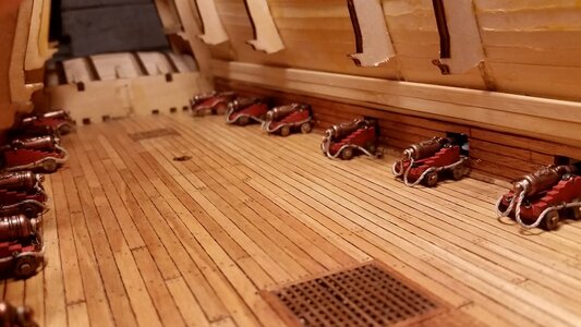
I took this picture later in the work, but this shows how the first cut was made into the rear bulkhead, flush with the deck.
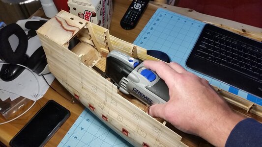
The bulkhead is gone.
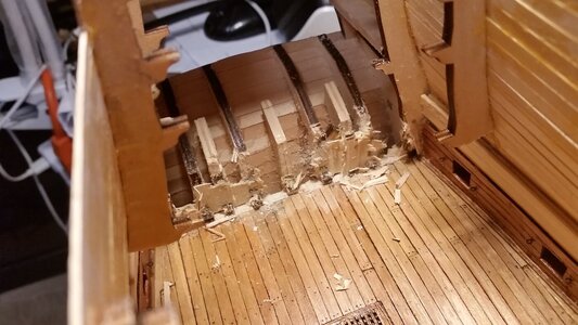
Removed the supports by cracking the glue joints with a twisting motion. Don't let the crunching sounds scare you.
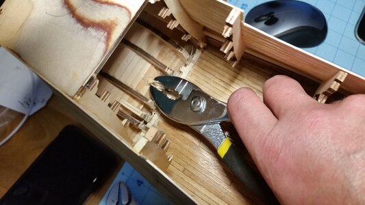
With the bulkhead and supports gone, there's a mess to clean up.
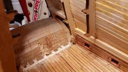
Cleaning up the mess with a razor knife and sanding stick.
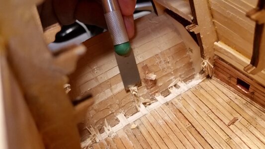
Not bad. Now the deck will be extended and the rear gun ports and stern transom built up with internal planks.
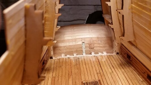
See that bulkhead back there? Let's WRECK IT!

I took this picture later in the work, but this shows how the first cut was made into the rear bulkhead, flush with the deck.

The bulkhead is gone.

Removed the supports by cracking the glue joints with a twisting motion. Don't let the crunching sounds scare you.

With the bulkhead and supports gone, there's a mess to clean up.

Cleaning up the mess with a razor knife and sanding stick.

Not bad. Now the deck will be extended and the rear gun ports and stern transom built up with internal planks.

- Joined
- Oct 9, 2020
- Messages
- 2,231
- Points
- 488

that must have been painful. glad to see it cleaned up nice, though
Oh, my! I was hoping for a massive broadside from the gun-deck cannons.Demolition Day! After working up some courage, I finally started making room in the stern area on the lower gun deck for the stern chaser guns.
See that bulkhead back there? Let's WRECK IT!
View attachment 265443
I took this picture later in the work, but this shows how the first cut was made into the rear bulkhead, flush with the deck.
View attachment 265437
The bulkhead is gone.
View attachment 265440
Removed the supports by cracking the glue joints with a twisting motion. Don't let the crunching sounds scare you.
View attachment 265439
With the bulkhead and supports gone, there's a mess to clean up.
View attachment 265438
Cleaning up the mess with a razor knife and sanding stick.
View attachment 265441
Not bad. Now the deck will be extended and the rear gun ports and stern transom built up with internal planks.
View attachment 265442
Not too bad. Just 1 minute of careful cutting, 10 minutes of crunching wood and 3 minutes of cleanup. All in the name of progress.that must have been painful. glad to see it cleaned up nice, though
Go to the sound of guns! Maybe it was crunching this time.Not too bad. Just 1 minute of careful cutting, 10 minutes of crunching wood and 3 minutes of cleanup. All in the name of progress.
I'm planning a similar partial demolition for my diorama if I ever get HMS Medea finished....Controlled demolition but with purpose and a good reason looks like the way to go. Thanks for sharing.
Looking back on it, I'm not sure I would have made the cutaway Black Pearl if I had to do it over again. More power to ya, Kurt!...because. Just because.
The model has to match the title of the build log. I am actually looking into installing borescopes, one on each deck, that you can access with your cell phone via bluetooth and see the decks individually. I know it's overkill, but I HATE the look of cutaway hulls.

