Wow, look at how bent the deck planks are. Mine are as straight as a board! It makes me wonder if I should have bent mine.Too keep the deck thin and close to scale, 3mmx3mm beams will be layered on the bottom of a false deck made from 3-ply, 1mm thick smooth plywood. The false deck will have tanganyika planks on the top surface, for the middle deck above.
1) If I assemble the beam knees and ends of the beams to the bulwarks, using McKay's book as a guide for placement (the only source I have), then the 1mm plywood false deck could be glued on top of this structure of beams, knees and columns in a series of pieces, divided left and right, and from bow to stern. Lastly, the middle gun deck planking can be glued to the false deck. Hopefully the false deck will be in contact with most if not all of the supporting structure without too many gaps. I will be have to be careful not to apply too much pressure on the plywood or risk collapsing the beam structure. One idea is to use a combination of CA and PVA glue. With most of the beams coated with wet PVA glue, several spots will be left bare. CA glue will be applied to these spots, and the plywood held there until it takes hold. This will hold the plywood tight to the support structure until the PVA dries. Or thin pins could be used at various angles to hold the deck ply to the structure. However, pushing pins in may collapse the delicate support structure. Uwe is using this method in his build.
2) Another approach, which takes a lot more careful measurement and fitting, is to attach deck support knees to the bulwarks, place support columns on the gun deck, then glue the beams to the underside of the false deck overhead instead of attaching them at the bulwarks to the knees and to the tops of the columns. The beams would have to be carefully plotted so they do non interfere with the knees, and the joints of the plywood deck pieces will have to be carefully fitted so the beams line up on the underside and there are no wide gaps. Seams would be position over beams to hide them from view underneath, so some beams would support the cut edges of the plywood above them. This method ensures a good bond of the beams to the false deck above.
In both methods, care must be taken to preserve the curvature of the deck in both camber and sheer, not an easy task using method 2). Another thing to watch is the height of the columns, to that the deck overhead contacts the top of each column as evenly as possible. Whatever I do, I want avoid that sickening *CRUNCH* of collapsing deck structure.
Wasa example, upper gun deck. Note the hanging knees connecting beams to inner side planking, heavy overhead beams and thinner ledges in between the knees, parallel to them. Carlings are the thin, wide boards running across the tops of the beams in perpendicular. View attachment 264990
Wasa example, lower gun deck. I can see only one lodging knee, oriented in the horizontal plane, between the beam and the interior planking. It is visible to the right of the closest fluorescent lamp on the right.
View attachment 264991
-

Win a Free Custom Engraved Brass Coin!!!
As a way to introduce our brass coins to the community, we will raffle off a free coin during the month of August. Follow link ABOVE for instructions for entering.
-

PRE-ORDER SHIPS IN SCALE TODAY!
The beloved Ships in Scale Magazine is back and charting a new course for 2026!
Discover new skills, new techniques, and new inspirations in every issue.
NOTE THAT OUR FIRST ISSUE WILL BE JAN/FEB 2026
You are using an out of date browser. It may not display this or other websites correctly.
You should upgrade or use an alternative browser.
You should upgrade or use an alternative browser.
HMS Sovereign of the Seas - Bashing DeAgostini Beyond Believable Boundaries
- Thread starter DARIVS ARCHITECTVS
- Start date
- Watchers 105
The lower gun deck was neatened up a bit. A Dremel with a diamond burr was used to cut the plywood structure below the level of the deck. A thick layer of plywood was laid down, then planked, and the inside of the counter (lower transom) was planked with bamboo strips from the kit and stained. The bamboo thickened and reinforced the counter in preparation for cutting the lower stern chase gun ports.
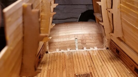
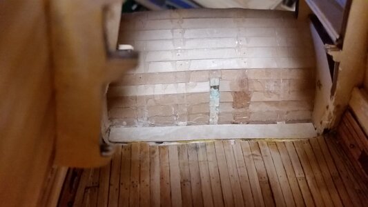
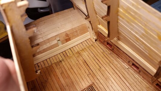
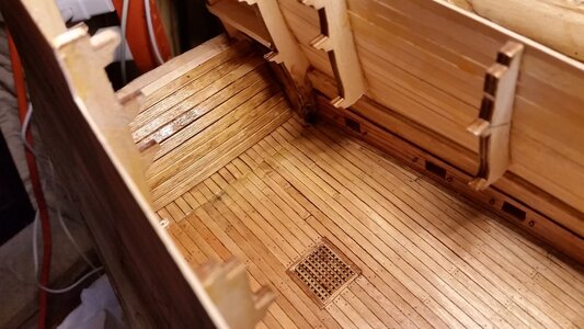
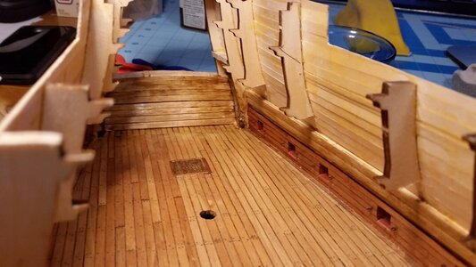


Last edited:
I like the look, Kurt. Does it weaken the support structure, do you think?The lower gun deck was neatened up a bit. A Dremel with a diamond burr was used to cut the plywood structure below the level of the deck. A thick layer of plywood was laid down, then planked, and the inside of the lower transom was planked with bamboo strips from the kit and stained. The bamboo thickened and reinforced the transom in preparation for cutting the lower stern chase gun ports.
View attachment 265590
View attachment 265591
View attachment 265592
View attachment 265593
View attachment 265594
No, the structure is quite sound. The counter has been reinforced by the inner planking. You can remove the inner support structure once the shell of the hull is created. However, one has to be careful to remove only those supports from the kit that will be replaced by other structures. The hull as it is now is a thin shell, prone to distortion from changes in moisture and holds its ship because of the frames provided by the kit. As the decks are completed from the bottom up, the kit's frames are being removed in sections and replace by the inner planking of the bulwarks and the hull sides anchored by the deck beams.I like the look, Kurt. Does it weaken the support structure, do you think?
There are times when, faced with a problem in making a kit accurate, that you have to be fearless in your decision to modify a ship model, after long careful consideration of the effects of that change on later steps in the build. I am at one such crossroad. In order to build the Sovereign in the form that she was initially built in 1635 with the guns closer to the water, I have to undo the features of this kit that were influenced by the form of the ship after 1660.
As I was looking at the deck height and gun port placement relative to the stern, it became apparent that the lower deck is a bit too high such that the stern chase guns would be located too high relative to the gun ports on the counter. This is because the of the kit's design as to the location of the lower deck. It may be possible to raise the counter up 5mm, and adjust all gun ports and decorations to come later. The entire stern will have to be re-evaluated. I think I can squeeze in the lower deck stern chasers with slightly lower gun carriages, but the middle gun deck gun port as drawn on the side of the hull are about 12mm too high as drawn, and the location of the middle gun deck and its ports will be adjusted to match the stern. The curve of the counter needs to be adjusted, so the top planks of that curve will have to be removed and replaced higher on the stern. All these changes came with a close study of the Willem van de Velde and Payne drawings and prints. Knowing that the van de Velde depicted the guns of the lower deck at the newer, high positions in his drawing resulting from the deck being raised in 1660, but mistakenly drew the two ports under the side galleries in their lower, original positions prior to 1660, when in fact they were eliminated, it is logical to assume that the reason DeAgostini designed the gun decks at their heights in the kit is because they copied the deck positions from the later rebuild of the Sovereign, not at the original, lower positions shown on Payne's print. The reason the gun decks were raised were obviously to raise the guns above the waterline to make the ship more seaworthy and such that it would not suffer the same fate as the Wasa. King Charles I had already ordered that the ship be loaded with more cannon that she had been designed for, and to make up for problems of that decision, many changes to the internal structure were made in 1659-60 to get more use out of the ship, including lightening of ship to reduce its draft by removing many of the heavy decorations prior to re-christening the ship HMS Royal Sovereign. With some tweaking, I may yet be able to align the level of the lower and middle gun ports from the sides to the stern, but without totally gutting and repositioning the lower gun deck, it will be difficult, and the proportions of the stern decorations as shown in the Lely Portrait of Peter Pett may not be successfully preserved. Uwe's solution was to change the shape of the counter and raise the upper transom, judging from his model photographs. It has become obvious that my build will have to follow a similar path. However, despite his changes, it does not appear that Uwe's counter will terminate as high on the stern as it appears in my sources. As a result, I think he may run into trouble with the placement of the middle deck stern chase guns.
Uwe's ship plan with interior decks shown in red
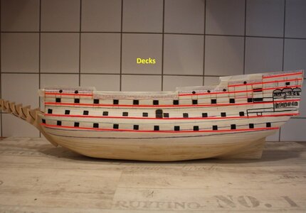
The proposed redesigned profile of the counter, bringing the top edge of the counter above the middle deck gun ports. My three principal sources, the Payne print, Willem van de Velde sketch, and the Lely Portrait of Peter Pett all seem to show the top of the counter terminating at level of the top of the middle gun ports. Looks like more demolition of the stern is in order.
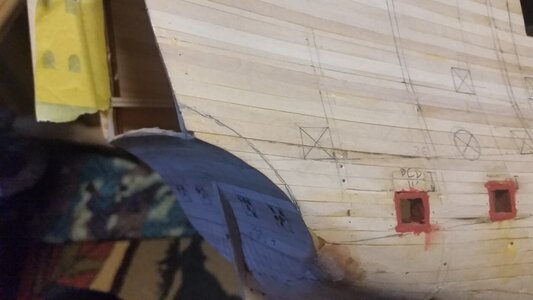
Last edited:
Ach, so!
WARNING: The following is not for the faint of heart. If you dread doing major hull surgery, you will be traumatized.
The upper portion of the counter was cut away and rebuilt. The counter piece was re-used. No models were harmed in the making of this modification.
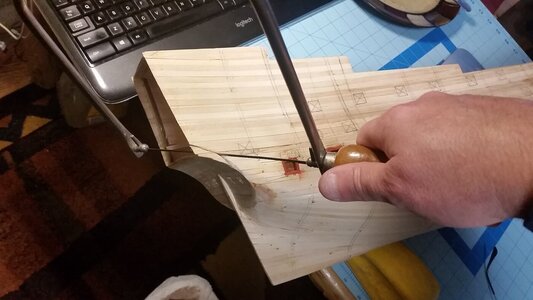
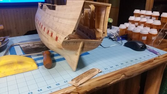
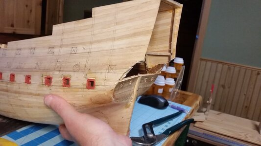
Salvaged and reused the counter section.
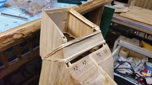
Used some scrap hull strips to fill in the counter
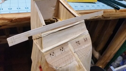
Profile looks better.
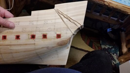
There! Now the stern chasers line up with the decks properly. The gun port positions were re-drawn. A few holes need to be patched, but I'd call this a success.
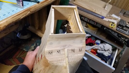
Added stained bamboo scrap strips as planks on the counter to reinforce it and provide thickness
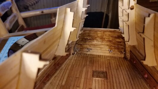
Uwe took a different approach. He extended the stern out a bit at the bottom, then rebuilt the profile of the counter. Interesting how we came to the same conclusion regarding the need to reshape the counter. If I had to start over, I would have lowered the lower gun deck, but it was too early in the build then to see which direction the hull shape was going.
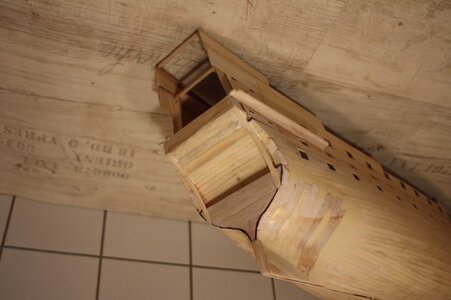
The upper portion of the counter was cut away and rebuilt. The counter piece was re-used. No models were harmed in the making of this modification.


Salvaged and reused the counter section.

Used some scrap hull strips to fill in the counter

Profile looks better.

There! Now the stern chasers line up with the decks properly. The gun port positions were re-drawn. A few holes need to be patched, but I'd call this a success.

Added stained bamboo scrap strips as planks on the counter to reinforce it and provide thickness

Uwe took a different approach. He extended the stern out a bit at the bottom, then rebuilt the profile of the counter. Interesting how we came to the same conclusion regarding the need to reshape the counter. If I had to start over, I would have lowered the lower gun deck, but it was too early in the build then to see which direction the hull shape was going.

Last edited:
- Joined
- Oct 9, 2020
- Messages
- 2,231
- Points
- 488

This is cringe worthy. Great job, though!
I moved a pin rail 3 mm once....
I just vomited.
- Joined
- Sep 3, 2021
- Messages
- 5,199
- Points
- 738

Please! Don't encourage him, before you know he cut his entire bow off because, well, whatever reason...The line is visually more aesthetic - great job! And as to drastic measures in drastic situations ... are you sure you do not have South African blood somewhere?
Please! Don't encourage him, before you know he cut his entire bow off because, well, whatever reason...


Despite the cringing of my fellow builders, DEMOLITION continues. Since the outboard stern chase gun portals are so close to the sides of the ship, the supports in the inside corners need to go away. Once again, my trusty Dremel plunge cutter was carefully used to make cuts in the wood supporting the inside supports, all without puncturing the thin hull planking. Then with lots of crunching sounds, a screwdriver was used to carefully pry the supports, breaking the glue joints to the outer planking skin of the sides and stern without tearing a hole in the hull. Experience with glue joints allows you to get away with crazy things like this. A needle nosed plier was used to crush the support into splinters, and it was removed in pieces. Crunching complete. Now, I had to put the wood back, albeit thinner on the sides, allowing room for the outermost gun tackled to be installed later without obstruction. Scrap linden wood from my last build was cut with a scissors and used as planks to fill the voids, then plank over them in the inside corners and along the outboard sides of the outboard gun ports.
The lower gun deck stern chase ports were cut into the counter with a Dremel rotary tool armed with a diamond burr, then filed to shape. The sills and new inside wood was stained with walnut stain. The precision of all the reconstruction was quite low, but no one will see it anyway, and it completes the deck. Stern chase guns need to be assembled next.
Scraps fill the holes in the sides, and the first plank is fitted outboard of the gun port
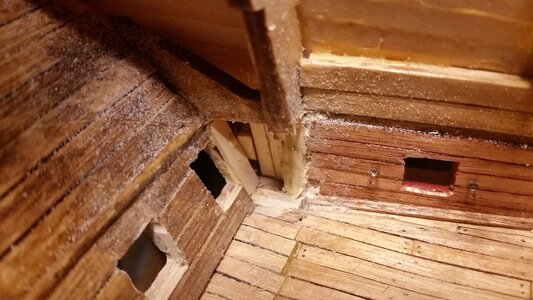
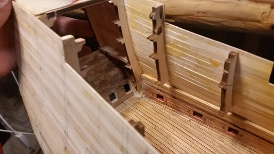
Gun ports are cut, with holes previously drilled outside the perimeter of one port filled with scrap woos and sanded flush
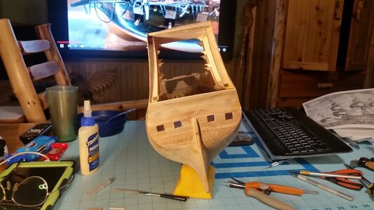
Not bad for a quick and dirty reconstruction job. The guns will cover up much of the ugly seam in the deck. Bashing at its finest.
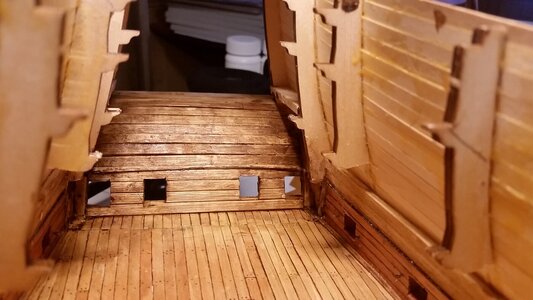
The lower gun deck stern chase ports were cut into the counter with a Dremel rotary tool armed with a diamond burr, then filed to shape. The sills and new inside wood was stained with walnut stain. The precision of all the reconstruction was quite low, but no one will see it anyway, and it completes the deck. Stern chase guns need to be assembled next.
Scraps fill the holes in the sides, and the first plank is fitted outboard of the gun port


Gun ports are cut, with holes previously drilled outside the perimeter of one port filled with scrap woos and sanded flush

Not bad for a quick and dirty reconstruction job. The guns will cover up much of the ugly seam in the deck. Bashing at its finest.

- Joined
- Sep 3, 2021
- Messages
- 5,199
- Points
- 738

I won't comment anymore on the demolition derby you're undertaking  , instead, I would like to address something else I find difficult to understand. So please, take no offense, but when looking at your last two pictures, I can't help but notice the close proximity of the two most outboard (port/starboard) gunports and the two aftmost gunports(again port/starboard) facing sideways. Do you still have sufficient room to be able to install the cannons, carriers and other hardware, without running into some interference issues?
Kind regards,
Johan
PS I admire your bravity, don't think I'd find the guts to go where you went with your build...
Kind regards,
Johan
PS I admire your bravity, don't think I'd find the guts to go where you went with your build...

bashing beyond believable boundaries... 
- Joined
- Oct 9, 2020
- Messages
- 2,231
- Points
- 488

eesh. another cringe-worthy moment. Good job, though.
- Joined
- Jan 9, 2020
- Messages
- 10,566
- Points
- 938

Hi Johan. If Kurt will allow me to chip in - aft guns were seldom permanently mounted. On the Dutch ships the two most rearward cannons were simply moved aft when the ship was being chased. If this was also the custom on British ships I don't know.I won't comment anymore on the demolition derby you're undertaking, instead, I would like to address something else I find difficult to understand. So please, take no offense, but when looking at your last two pictures, I can't help but notice the close proximity of the two most outboard (port/starboard) gunports and the two aftmost gunports(again port/starboard) facing sideways. Do you still have sufficient room to be able to install the cannons, carriers and other hardware, without running into some interference issues?
Kind regards,
Johan
PS I admire your bravity, don't think I'd find the guts to go where you went with your build...
After watching the video on the Batavia, I presume they used a smaller bore gun with a doubled range for chase guns. That way they could hit from farther away. Are you planning on using a different gun for the chase Jagtkannone?

