-

Win a Free Custom Engraved Brass Coin!!!
As a way to introduce our brass coins to the community, we will raffle off a free coin during the month of August. Follow link ABOVE for instructions for entering.
-

PRE-ORDER SHIPS IN SCALE TODAY!
The beloved Ships in Scale Magazine is back and charting a new course for 2026!
Discover new skills, new techniques, and new inspirations in every issue.
NOTE THAT OUR FIRST ISSUE WILL BE JAN/FEB 2026
You are using an out of date browser. It may not display this or other websites correctly.
You should upgrade or use an alternative browser.
You should upgrade or use an alternative browser.
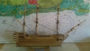
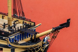
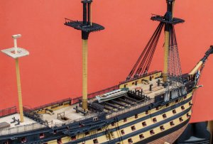
HMS Victory 1/72 Caldercraft
- Thread starter nick-edw
- Start date
- Watchers 25
-
- Tags
- caldercraft victory
!!!!impresionante!!!!Pulgares hacia arriba
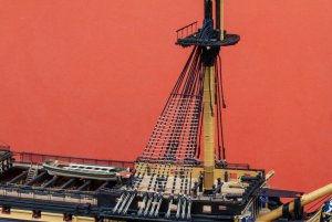
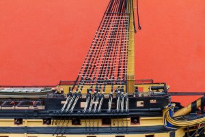
Here’s my technique for hammock nets. I make a folded paper template and cut some tulle slightly oversize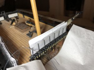 I put some weight (a scalpel is the right size and shape I find) to ensure the net conforms to the hammock cranes, then stitch the first vertical edge.
Then fold the top edge of net over and start stitching.
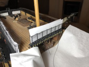
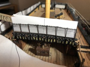
Then lock everything off with diluted PVA
and trim when dry
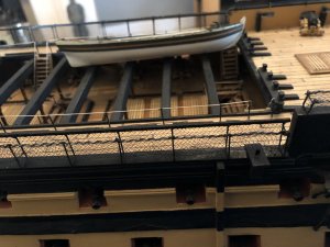
There may well be a better way of doing this but this works for me!
Regards
Nick
 I put some weight (a scalpel is the right size and shape I find) to ensure the net conforms to the hammock cranes, then stitch the first vertical edge.
Then fold the top edge of net over and start stitching.


Then lock everything off with diluted PVA
and trim when dry

There may well be a better way of doing this but this works for me!
Regards
Nick
Last edited:
Absolutely stunning work Nick.
The detail in your cockpit is unbelievable.
Caldercraft Victory is on my wish list, but I am afraid, well beyond my abilities at this stage.
The detail in your cockpit is unbelievable.
Caldercraft Victory is on my wish list, but I am afraid, well beyond my abilities at this stage.
Thats a huge and very ambitious project. Great stuff.
Like it! At least you finished yoursYour ship..my ship... like the movie twins with Arnold and Danny..(tongue-in-cheek). Awesome build with
many valuable ideas. TKS...View attachment 80214
Hi everyone, I’ve been doing a bit more work on my Victory.
I was never very happy with my mast-making set up, I have a model engineers metal working lathe, and a little ‘toy’ mantua lathe I’ve never really used.
So I thought I would put some effort into getting a better setup.
The main issue with the mantua lathe, is it’s all made out of polycarbonate so the Chuck is a bit rubbish and doesn’t tighten properly, so long thin pieces slip, whip and destroy themselves.
To cut a long story short, I decided to start drilling some holes in it...
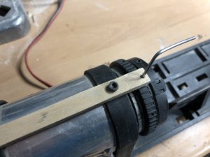
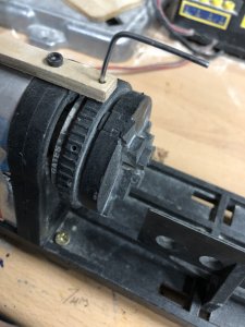
So one in the tightening ring to get some leverage, with a steel rod inserted, which transformed it into a useful bit of kit from someting I was about to abandon, so while I was drill-happy, I also drilled 8 indexing holes and added a ply strip as you can see, that gave me the ability to cut squares and octangons easily as well as turning.
This works really well I think:
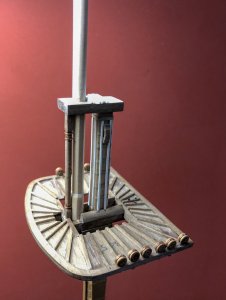
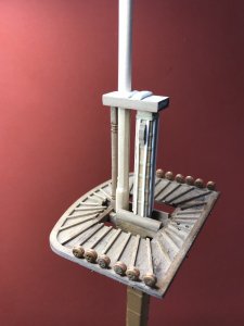
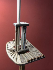
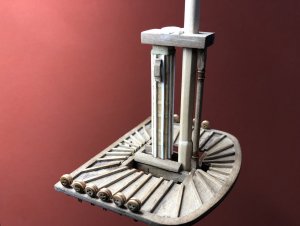
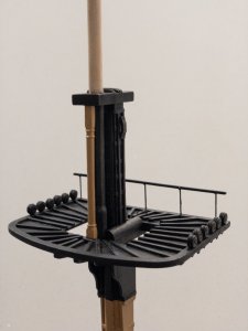
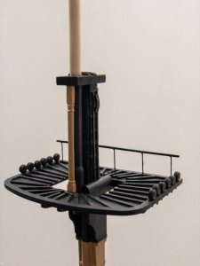
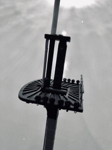
I was never very happy with my mast-making set up, I have a model engineers metal working lathe, and a little ‘toy’ mantua lathe I’ve never really used.
So I thought I would put some effort into getting a better setup.
The main issue with the mantua lathe, is it’s all made out of polycarbonate so the Chuck is a bit rubbish and doesn’t tighten properly, so long thin pieces slip, whip and destroy themselves.
To cut a long story short, I decided to start drilling some holes in it...


So one in the tightening ring to get some leverage, with a steel rod inserted, which transformed it into a useful bit of kit from someting I was about to abandon, so while I was drill-happy, I also drilled 8 indexing holes and added a ply strip as you can see, that gave me the ability to cut squares and octangons easily as well as turning.
This works really well I think:


Absolutely incredible !!! Your other models too - stunning -
Wow, everything you have done on this model is fantastic. Well done.
We can see the quality of the kit, but especially of your work - looking very good 

As an old IT guy I 'm very familiar with servers and of course the humble mouse. Just not this kind:-
first I turned down a former for the mouse from scrap dowel, I drilled it out first to suit the diameter of the thread it was going on :-
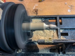
I've modified my home made server (see earlier post) by drilling out a couple of nylon gears I had lying around to suit the tubes on the server rig, then laced the teeth with .25mm thread like this:-
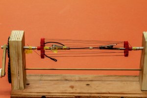
carefully and evenly, nip them all in at the base of the tapered end of the wooden mouse former I turned earlier:-
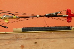
then start darning (which is the correct term for this I believe?)
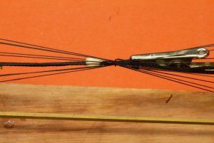
Some time (and knitting) later:-
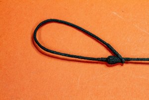
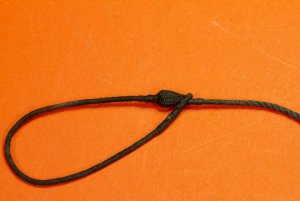
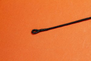
not the easiest thing in the world to make, but got there in the end!
thanks for looking
Nick
first I turned down a former for the mouse from scrap dowel, I drilled it out first to suit the diameter of the thread it was going on :-

I've modified my home made server (see earlier post) by drilling out a couple of nylon gears I had lying around to suit the tubes on the server rig, then laced the teeth with .25mm thread like this:-

carefully and evenly, nip them all in at the base of the tapered end of the wooden mouse former I turned earlier:-

then start darning (which is the correct term for this I believe?)

Some time (and knitting) later:-


not the easiest thing in the world to make, but got there in the end!
thanks for looking
Nick
Nick,
Just found your log. As all have said brilliant work. How you wove the mouse is so perfect as well - I'll grab a chair and follow along
Cheers,
Just found your log. As all have said brilliant work. How you wove the mouse is so perfect as well - I'll grab a chair and follow along
Cheers,
Hi Nick,
Brilliant result. What did you use to tar your rope? Looks very realistic.
Brilliant result. What did you use to tar your rope? Looks very realistic.
The result of your mouse is very good - interesting jig
-> would be a good basis for a small tutorial (if it allowed to say ?!?)
-> would be a good basis for a small tutorial (if it allowed to say ?!?)
Thanks for the kind remarks.Hi Nick,
Brilliant result. What did you use to tar your rope? Looks very realistic.
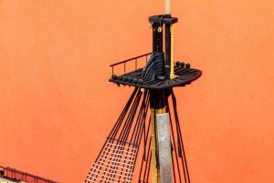
I coated everything with very thinned down PVA (white woodwork adhesive) mostly to reduce fuzz, but also to lock everything in a bit. I know it's against the law, but I do use superthin CA adhesive for the construction of these things. I apply it with a thin wire, never directly from the tube, and tiny amounts are needed due to the wicking effect of the thread, it can leave a slight gloss behind, so everything is then painted with thinned down Tamiya Flat black paint. I then dry-brush with dark grey to pop the detail.
I've done a lot of modelling with photo etch, and finely honed my technique for applying tiny, near-invisible amounts of CA.
Basically, get a bottle top or lid, stretch some ordinary cooking foil across the top, and push a slight indent into it making a wok shape, put a small pool of good quality, modelling grade ultra-thin CA into this.
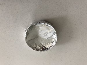
Then use something like the wrong end of a paintbrush and wind a dozen or so turns of very thin copper wire (22 SWG or so - sorry don't what this is in AWG offhand, I'm sure google knows) an pull the last straight 2cm to make your applicator.
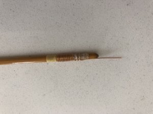
Surface tension, wicking and capillary action then does all the work for you, dip the wire in the CA, you probably won't be able to see it which is correct and where most people go wrong and apply too-much!, then touch it into the piece and wicking (in the case of rigging) or capillary action (in the case of PE) will pull the minimum amount of CA into the joint. NOTE - You probably wont see anything, this is OK, it's like magic the first time you do it correctly, it's just bonded! this is where it generally goes wrong as people keep on applying more until they can see the CA - DON'T!
CA will build up on you wire, hence the 12 turns, simply snip the last few mm off, unwind a bit more and carry on.
the wire needs to be very thin so when its pushed into the angle of the joint, it's close enough for capillary action to bridge the space and pull the CA off the applicator.
My zero was built entirely using this technique, and as it remains bare-metal, there is no margin for being able to see glue - I'm not suggesting it's perfect by any means, but CA spread is minimal I think:-
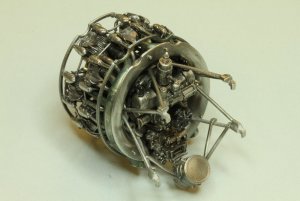
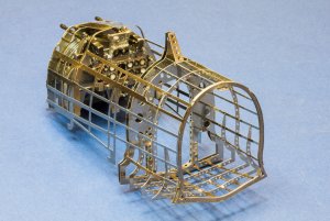
hope this useful for someone.
Nick
Last edited:
Thank you very much, Nick, for detailed instructions. Very precision work on the engine and cockpit! Both looking excellent!


