Beautiful work Sergey. Thanks for sharing your assembly. I am learning plenty new tips. Cheers Grant07.2024
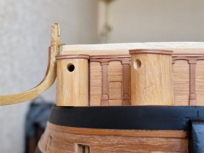
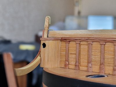
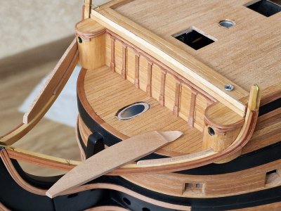
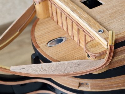
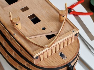
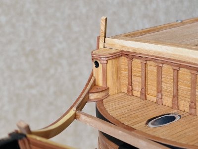
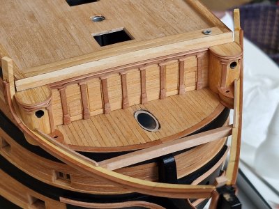
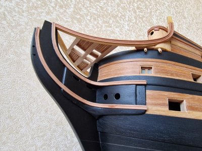
So, continuing the assembly diary... I got so carried away with making this part that I forgot to photograph the calculation process for it—the part that supports the entire head structure. The radius was too large to bend such a thick plank, and the only wide plank I had was made of gray boxwood. With no better option, I used it. I cut it according to a pre-calculated curve, which took a long time to determine because McKay's plans for the head structure had a significant error in the deck and superstructure. I’ve written about this earlier.
As a result, the curve of this part was adjusted through trial fittings and modifications. Moreover, in the plans, this part was only shown from the top, bottom, and side views, but its diagonal dimensions were not provided. So, the design had to be visualized from a perspective not included in the plans. For reference, I used drawings from another source, adjusting the curvature to fit my dimensions.
Ultimately, I glued a decorative plank onto the boxwood arc and bent it where possible. For areas where the radius was too tight, I created a composite structure. I understand this approach isn’t entirely accurate to the anatomy, but replicating the original method wasn’t feasible for me. So, I improvised. On the left side, by the way, it’s coated with oil, and any traces of superglue are invisible—only the wood joints are visible, as I mentioned earlier.
View attachment 483641
View attachment 483642
View attachment 483643
The process was further complicated by the need to fit this part to the midshipmen's toilets. However, in the end, I was very pleased with the result. It turned out symmetrical, and finally, something is starting to take shape.
View attachment 483644
View attachment 483645
View attachment 483646
View attachment 483647
View attachment 483648
View attachment 483649
This is just an intermediate result. Up next are the grates of the head... and then only two more parts will remain before I catch up to the present.

-

Win a Free Custom Engraved Brass Coin!!!
As a way to introduce our brass coins to the community, we will raffle off a free coin during the month of August. Follow link ABOVE for instructions for entering.
-

PRE-ORDER SHIPS IN SCALE TODAY!
The beloved Ships in Scale Magazine is back and charting a new course for 2026!
Discover new skills, new techniques, and new inspirations in every issue.
NOTE THAT OUR FIRST ISSUE WILL BE JAN/FEB 2026
You are using an out of date browser. It may not display this or other websites correctly.
You should upgrade or use an alternative browser.
You should upgrade or use an alternative browser.
HMS Victory [1805] 1:79 by serikoff. Started with Mantua -> Upgraded with John McKay's Anatomy.
Fantastic stuff, your work, the pictures, and how you explain everything. Thanks for taking the time to show all this Serikoff.
Thank you, friends.Beautiful work Sergey. Thanks for sharing your assembly. I am learning plenty new tips. Cheers Grant
I was glad to help. If you have any questions, don't hesitate to contact me
Part 21
07.2024
So, while I'm currently working on teak oil samples, today we'll continue looking back at how I constructed the head.
Briefly, my experiments with oil application are going well so far. I've already applied several layers to the deck and hull sample, but I'll provide a detailed update later, once there are longer-term results. I'm also coating the stand with teak oil. There will be many layers, as I'm aiming for a perfect glossy, deep shine, but more on that later. For now—back to the head...
Work continued on the midshipmen's toilets. I attached decorative planks to them, then glued two curved pieces together and attached four toilets to them—two for the midshipmen and two adjacent, shaped like half-moons. The photos will best illustrate what was done.
...
07.2024
So, while I'm currently working on teak oil samples, today we'll continue looking back at how I constructed the head.
Briefly, my experiments with oil application are going well so far. I've already applied several layers to the deck and hull sample, but I'll provide a detailed update later, once there are longer-term results. I'm also coating the stand with teak oil. There will be many layers, as I'm aiming for a perfect glossy, deep shine, but more on that later. For now—back to the head...
Work continued on the midshipmen's toilets. I attached decorative planks to them, then glued two curved pieces together and attached four toilets to them—two for the midshipmen and two adjacent, shaped like half-moons. The photos will best illustrate what was done.


...
Your work here is beautiful, Sergey!
I'm confident you know this but just in case: beware of the surfaces treated with tung oil - they will no longer take glue well (you will find the bond strength very weak for anything you glue to tung oil treated wood).
I'm confident you know this but just in case: beware of the surfaces treated with tung oil - they will no longer take glue well (you will find the bond strength very weak for anything you glue to tung oil treated wood).
Thank you for the praise, it's very nice. Yes, I've heard about this property. I'm just experimenting with the number of layers and how it will affect the gluing. I plan to do it this way so that after processing there are no places where the glue will have a holding function. Most likely, if I glue and will be on top of the oil, then only in those cases when the fixation of these parts will have a decorative character and not a force one. Thanks for the warning.Your work here is beautiful, Sergey!
I'm confident you know this but just in case: beware of the surfaces treated with tung oil - they will no longer take glue well (you will find the bond strength very weak for anything you glue to tung oil treated wood).
I'm trying to test the truth of the words that if you let the teak oil dry well and glue it with cyanoacrylate, then the glue will be reliable enough. So we'll check))
07.2024
While I am working on test pieces for the stern gallery, today I will show how I made the grates for the bow section of the ship.
This will include two parts at once. On drafting paper, I marked the lines for the beams between which the grates would be placed. All dimensions were taken from the anatomy plans, which I printed at a 1:1 scale.
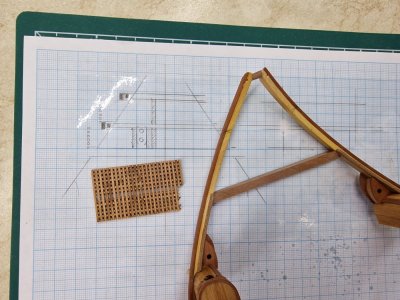
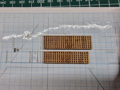
I prepared templates for both sides at once. Using an angle sander, I sanded the required angle and glued a strip to the edge.
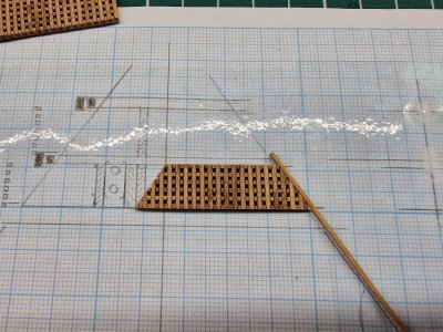
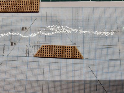
The finished piece just needed to be cut into two parts and glued into the required positions. Beams are placed between the grates, and the process with the grates is repeated.
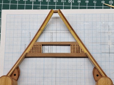
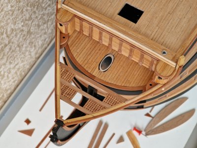
...
While I am working on test pieces for the stern gallery, today I will show how I made the grates for the bow section of the ship.
This will include two parts at once. On drafting paper, I marked the lines for the beams between which the grates would be placed. All dimensions were taken from the anatomy plans, which I printed at a 1:1 scale.


I prepared templates for both sides at once. Using an angle sander, I sanded the required angle and glued a strip to the edge.


The finished piece just needed to be cut into two parts and glued into the required positions. Beams are placed between the grates, and the process with the grates is repeated.


...
07.2024
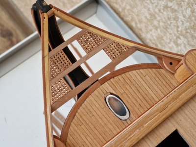
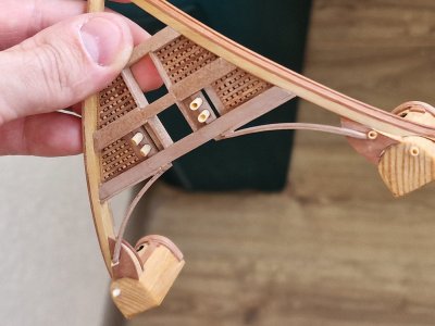
The gaps between the beams were then filled with cross inserts, forming four rectangular openings—two for the toilets and two for the ropes.
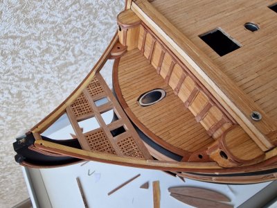
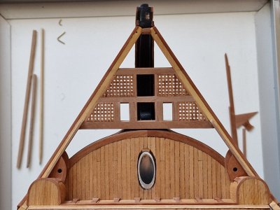
Simultaneously, I glued in sewage pipes leading from the midshipmen's toilets and the adjacent ones. The pipes in the center of the forecastle are still removable. I adjusted their geometry, leaving only the painting to be done.
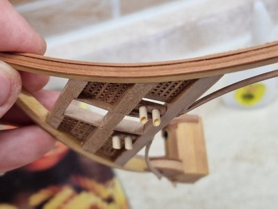
Rarely have I seen modelers pay attention to these elements, but I believe they are a logical detail. I researched the literature, and the information varies: some sources say the sewage pipes had a square cross-section, others claim they were round; some depict the pipes as simple cylinders, while others show them beveled like a needle. Ultimately, I chose the latter based on logical reasoning. It was easier for me to create a cylinder of this diameter, and I assume the bevel was used to save material and weight—though I might be wrong. Nevertheless, the decision is made, so this is how it will be.
...

The gaps between the beams were then filled with cross inserts, forming four rectangular openings—two for the toilets and two for the ropes.


Simultaneously, I glued in sewage pipes leading from the midshipmen's toilets and the adjacent ones. The pipes in the center of the forecastle are still removable. I adjusted their geometry, leaving only the painting to be done.


Rarely have I seen modelers pay attention to these elements, but I believe they are a logical detail. I researched the literature, and the information varies: some sources say the sewage pipes had a square cross-section, others claim they were round; some depict the pipes as simple cylinders, while others show them beveled like a needle. Ultimately, I chose the latter based on logical reasoning. It was easier for me to create a cylinder of this diameter, and I assume the bevel was used to save material and weight—though I might be wrong. Nevertheless, the decision is made, so this is how it will be.

...
Wielkie dzięki. Na dziobie statku jest jeszcze coś do pokazania. Niedługo skończy się dziennik budowy i opiszę co aktualnie robię))Witaj
Piękna praca, oglądam ją z przyjemnością. Pozdrawia Mirek
- Joined
- Dec 3, 2022
- Messages
- 1,547
- Points
- 488

That isn't a window for leaning out from on a quiet evening at sea!

Very smart work as always Sergey.

By the way, I will be redoing the window. But as always))) it will be a little later))That isn't a window for leaning out from on a quiet evening at sea!
Very smart work as always Sergey.
07.2024
Let's continue... I decided to switch things up and try my hand at making spars myself. As I mentioned earlier, I had the masts turned by a lathe operator because those parts were far more complex (which I’ll discuss later). Then I had a brilliant idea: to take a screwdriver and a sanding machine and attempt to make a round spar blank myself.
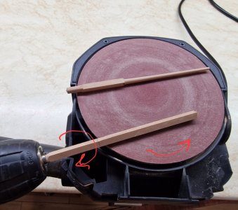
And it worked! I couldn’t believe it during the process, but the result far exceeded my expectations.
The principle is simple: insert a square blank into the screwdriver (I didn’t even round it beforehand, though that’s an option). Then, sand it at an angle so that the rotations, as shown in the earlier photo, meet each other as if they were counter-rotating. By carefully adjusting the angle, pressure, and abrasiveness, I achieved an excellent and repeatable final result.
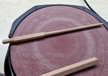
Not only did the tapered cylinders come out perfectly smooth and even, but the octagonal part of the piece transitioned seamlessly into the cylinder, rather than the other way around. That is, I didn’t make the octagon from a cylinder but correctly shaped the cylinder from an octagon.
Using this method, it’s possible to create the entire mast system—yards, topmasts, and more. As for these specific pieces, I’m not sure of their exact names. They were fixed on the bow and served as supports for the fore braces, if I’m not mistaken.
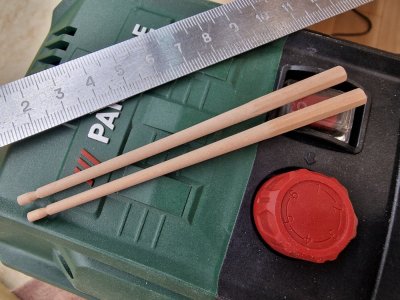
Honestly, I didn’t think this method could produce such precise and, more importantly, repeatable parts. I haven’t come across this technique before, though it’s possible someone else might have thought of it too. I hoped it would work, but the results pleasantly surprised me.
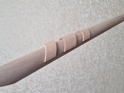
Continuing with the mast system, I returned to the bowsprit—specifically, to the stopper pads for the standing rigging on it. From the hollow cylinder that the turner made for me, I sanded an angle on the grinding machine.
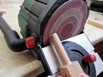
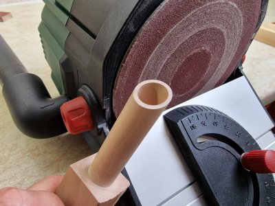
Then, I cut a fragment to the required length and sanded it parallel to the cut, securing the part with double-sided tape.
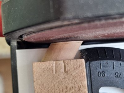
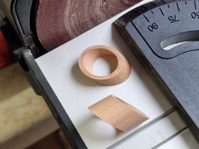
Here are the resulting blanks, which will be cut in half and glued onto the bowsprit as stoppers.
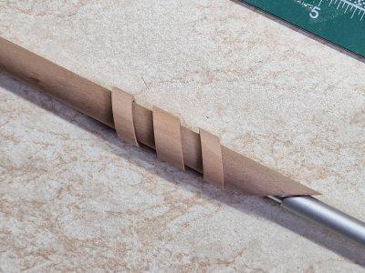
The nearly finished parts have been fitted to the bowsprit. What do you think of the result?
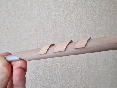
...
Let's continue... I decided to switch things up and try my hand at making spars myself. As I mentioned earlier, I had the masts turned by a lathe operator because those parts were far more complex (which I’ll discuss later). Then I had a brilliant idea: to take a screwdriver and a sanding machine and attempt to make a round spar blank myself.

And it worked! I couldn’t believe it during the process, but the result far exceeded my expectations.
The principle is simple: insert a square blank into the screwdriver (I didn’t even round it beforehand, though that’s an option). Then, sand it at an angle so that the rotations, as shown in the earlier photo, meet each other as if they were counter-rotating. By carefully adjusting the angle, pressure, and abrasiveness, I achieved an excellent and repeatable final result.

Not only did the tapered cylinders come out perfectly smooth and even, but the octagonal part of the piece transitioned seamlessly into the cylinder, rather than the other way around. That is, I didn’t make the octagon from a cylinder but correctly shaped the cylinder from an octagon.
Using this method, it’s possible to create the entire mast system—yards, topmasts, and more. As for these specific pieces, I’m not sure of their exact names. They were fixed on the bow and served as supports for the fore braces, if I’m not mistaken.

Honestly, I didn’t think this method could produce such precise and, more importantly, repeatable parts. I haven’t come across this technique before, though it’s possible someone else might have thought of it too. I hoped it would work, but the results pleasantly surprised me.
Continuing with the mast system, I returned to the bowsprit—specifically, to the stopper pads for the standing rigging on it. From the hollow cylinder that the turner made for me, I sanded an angle on the grinding machine.


Then, I cut a fragment to the required length and sanded it parallel to the cut, securing the part with double-sided tape.


Here are the resulting blanks, which will be cut in half and glued onto the bowsprit as stoppers.

The nearly finished parts have been fitted to the bowsprit. What do you think of the result?


...
- Joined
- Dec 3, 2022
- Messages
- 1,547
- Points
- 488

As for these specific pieces, I’m not sure of their exact names. They were fixed on the bow and served as supports for the fore braces, if I’m not mistaken.
They are called bumpkins.
You are obviously delighted with your woodworking today. And with good reason. It's all very well done.

- Joined
- Jul 18, 2024
- Messages
- 475
- Points
- 323

I am stunned by the detail and craftsmanship! Beautifully done.
Thanks for the title and praise. I have a dictionary of marine terms, but now I need to use a translator of marine terms, because sometimes a regular translator writes such things that I am shocked when I translate it back into my language to check))They are called bumpkins.
You are obviously delighted with your woodworking today. And with good reason. It's all very well done.
Thank you for your high ratingI am stunned by the detail and craftsmanship! Beautifully done.

- Joined
- Sep 8, 2024
- Messages
- 203
- Points
- 88

Crystal clear. Even I can follow that.Painting Rigging Threads.
1. I'll demonstrate the painting process using the threads I currently work with:
Gutermann scala 360 color 111, Amann Serafil 120 color 1000.
This can also be done with similar types of thread: Gutermann Tera180 color 111.
I do not use colored threads from these manufacturers either, as all polyester threads have a shine, which I do not like.
2. All the threads I use are in a milky color. Therefore, the results I show apply specifically to this color only.
3. I follow Dmitry Shevelev’s method for coloring, using oil-based artist paints, but with special preparation beforehand.
4. There are two color combination options. I’ll start with the one I initially used, but I’ll be painting the rigging on my ship using the second option. I like both, so I’ll show both.
5. The painting process involves dipping the thread into a reservoir of paint with a brush and pulling the thread under the brush while it is submerged in the paint. After a couple of minutes, we let the paint soak in and then dab off the excess with a paper towel. We don't wipe; we dab.
6. The threads take a couple of days to dry, after which they can be used. For those interested, the smell completely dissipates within a month.
7. It's best to dry the threads stretched out. I tie loops at the ends of the threads and stretch them tightly between two nails fixed on a board. You could hang a weight, but the first method is more convenient.
8. After drying, the threads become slightly stiffer, but not too much. I actually like this, as it makes them easier to work with. If anyone finds this inconvenient, simply kneading them a bit will soften them up.
9. Attention! The paint does not adhere to areas glued with super glue. Therefore, gluing should only be done after painting!
Method one.
The color scheme is similar to this appearance.
View attachment 482001
To achieve the colors shown in the photo above (dark brown and reddish-brick), we need two oil paints.
View attachment 482002 View attachment 482003
To achieve the dark brown color (for the standing rigging), I made a test sample with the following proportions:
5 ml of linseed oil + 5 ml of solvent + 5 cm of squeezed (natural) raw umber paint.
Explanation! The solvent I use is odorless, sold in art stores, specifically for thinning oil paints. The 5 cm refers to a strip of paint squeezed through the opening, which is equal to 5 cm. To make a larger batch, simply increase all ingredients proportionally.
To achieve the reddish-brick color (for the running rigging), you need:
5 ml of linseed oil + 5 ml of solvent + 5 cm of golden ochre + 2.5 mm of (natural) raw umber (no more!).
Explanation! If you add more umber, it will result in a completely different color, and it will be very difficult to achieve the desired shade from that. Therefore, it's better to add very small amounts.
And here is the result. By the way, in the photo, there is a color where I added more than 2.5 mm of umber (the second thread from the right in the photo). Some might prefer that specific color.
View attachment 482004
View attachment 482005
Method two.
I liked the color combination more, and it closely resembles the rigging colors on Dmitry Shevelev's 75-gun ship. I will paint my threads in these colors.
View attachment 482006
To achieve the colors shown in the photo above (dark brown and reddish-brick), we need two oil paints.
View attachment 482007 View attachment 482008
To achieve the dark brown color (for the standing rigging), I made a test sample with the following proportions:
5 ml of linseed oil + 5 ml of solvent + 5 cm of squeezed (natural) raw umber paint.
Explanation! The solvent I use is odorless, sold in art stores, specifically for thinning oil paints. The 5 cm refers to a strip of paint squeezed through the opening, which is equal to 5 cm. To make a larger batch, simply increase all ingredients proportionally.
For the running rigging, a different ochre is needed, yellow! Here are the proportions:
5 ml of linseed oil + 5 ml of solvent + 3.5 cm of yellow ochre + 3-6 mm of raw umber (no more).
Explanation! If you add more than 7 mm of umber, the color will change. However, in this case, unlike with the golden ochre, it can be corrected by adding oil, solvent, and ochre while reducing the amount of umber. Below, I will show the difference in color between using 3 mm or 6 mm of umber.
And here is the result. I will focus on this.
View attachment 482009
View attachment 482010
In the two photos above, in order from left to right: the first is the standing rigging (umbra); in the center, the third is yellow ochre + 3 mm of umbra; the right two are 6 mm (hence the color is slightly darker). You can actually play with the shades here. For areas with various weavings in the running rigging, you could use some with 3 mm and others with 6 mm as an option.
In the photo below, the leftmost rope features a lanyard. I made it following Shchevelev's method. First, the rope is dyed with umbra, then impregnated with cyanoacrylate for rigidity during lanyarding. After that, the lanyarding is done, followed by the painting of the finished rope. The lanyarding was done with Amann Serafil 60, so the color is slightly different after dyeing since the thread is not milk-colored but simply white. I will experiment further with this. Additionally, the lanyarding was a trial run, and it needs to incorporate thinner threads; I will discuss this more later.
View attachment 482011
View attachment 482012
Overall, I liked the samples, and while there's still much I will try and experiment with, the result I've achieved is clear and very satisfactory to me.
If there are any questions, I'll be happy to help.

The first photos of finished rigging reallly show the value of the careful attention given
As an observation though, I think I would aim for several different shades if I were aiming to depict a working, slightly weathered ship (my preferred look). Ropes will be of different ages, and therefore different colours, and fibre rope has that hairy look that may need light sandpapering to try and get that look showing that it has been through a sheave many, many times.
When you speak of lanyarding, is that what I know as ‘worm, parcel and serving’ ?
Jim
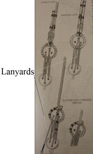
In maritime terms, a lanyard is a short length of rope or wire used to fasten or extend rigging. A typical example are pieces of small rope such as those rigging two deadeyes together. The first drawings below are from James Lees' The Masting and Rigging English of Ships of War, page 42. The second is from the internet showing the worming on the right, parceling in the middle and spun yarn serving on the left.lanyarding
Allan

Last edited:
Painting is not a predictable process at all. Therefore, a small difference in color will be in people's case. But I do not want a big difference, except perhaps insignificant, as it will most likely be.Crystal clear. Even I can follow that.
The first photos of finished rigging reallly show the value of the careful attention given
As an observation though, I think I would aim for several different shades if I were aiming to depict a working, slightly weathered ship (my preferred look). Ropes will be of different ages, and therefore different colours, and fibre rope has that hairy look that may need light sandpapering to try and get that look showing that it has been through a sheave many, many times.
When you speak of lanyarding, is that what I know as ‘worm, parcel and serving’ ?
Jim
The bottom picture is reinforcing the ropes from rubbing against wood or sails. I can't wait to do this))In maritime terms, a lanyard is a short length of rope or wire used to fasten or extend rigging. A typical example are pieces of small rope such as those rigging two deadeyes together. The first drawings below are from James Lees' The Masting and Rigging English of Ships of War, page 42. The second is from the internet showing the worming on the right, parceling in the middle and spun yarn serving on the left.
Allan
View attachment 484156View attachment 484157
- Joined
- Jul 27, 2021
- Messages
- 444
- Points
- 323

For blackening brass I use this, German Shop:

 www.regner-dampftechnik.com
For the patina on the copper you just need winegear and salt, nothing more.

Dirk

Messingfärber/ Kaltbrünierer 100 ml | REGNER
Vor dem Brünieren die Bauteile entfetten. Am besten durch Sandstrahlen, oder Schleifen, Schmirgeln.Ein gutes Mittel ist auch ein heißes Spülmittelwasserbad. Nach 10 min. abspülen und trocknen lassen.Bei Kaltbrünierung wird nach ca. 10 Minuten das Bauteil schwarz. Herausnehmen, abspülen und...
 www.regner-dampftechnik.com
For the patina on the copper you just need winegear and salt, nothing more.

Dirk
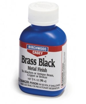
For blackening copper, or rather bluing, I will use gun bluing liquid, it is available in my country.For blackening brass I use this, German Shop:

Messingfärber/ Kaltbrünierer 100 ml | REGNER
Vor dem Brünieren die Bauteile entfetten. Am besten durch Sandstrahlen, oder Schleifen, Schmirgeln.Ein gutes Mittel ist auch ein heißes Spülmittelwasserbad. Nach 10 min. abspülen und trocknen lassen.Bei Kaltbrünierung wird nach ca. 10 Minuten das Bauteil schwarz. Herausnehmen, abspülen und...www.regner-dampftechnik.com
For the patina on the copper you just need winegear and salt, nothing more.

Dirk
But regarding patina, I wonder what kind of method with wine and salt is this, can you tell me more?


