Thank you for the kind words, I am very pleased.Wow wow wow. This is beautiful work Sergey. Innovative methods. Thank you for taking the time to take instructive photos and posting here on SoS.
Please continue to share your methods and skill.
It’s a visual masterclass.
Michael
-

Win a Free Custom Engraved Brass Coin!!!
As a way to introduce our brass coins to the community, we will raffle off a free coin during the month of August. Follow link ABOVE for instructions for entering.
-

PRE-ORDER SHIPS IN SCALE TODAY!
The beloved Ships in Scale Magazine is back and charting a new course for 2026!
Discover new skills, new techniques, and new inspirations in every issue.
NOTE THAT OUR FIRST ISSUE WILL BE JAN/FEB 2026
You are using an out of date browser. It may not display this or other websites correctly.
You should upgrade or use an alternative browser.
You should upgrade or use an alternative browser.
HMS Victory [1805] 1:79 by serikoff. Started with Mantua -> Upgraded with John McKay's Anatomy.
BrilliantPart 20
07.2024
The next element at the bow of the ship I started working on was the beakhead gallery, including its ports and doors.
View attachment 483321
On the balsa base, I glued pearwood planks with openings for the doors and ports. Based on the anatomy plans, I determined the placement of these features, as well as the columns and other decorative elements. I crafted a couple of shaped planks using the scraping method and prepared one wavy blank.
View attachment 483322
View attachment 483323
Next, I installed the doors and port lids and fitted the finished panel to the model, adjusting it to align with the side midshipmen’s toilets.
View attachment 483324
I made the toilets themselves from a block of linden. First, I shaped it properly and then covered it around the perimeter with thin plates of daru.
View attachment 483325
The intermediate result after creating the upper surfaces of the midshipmen's toilets.
View attachment 483326
View attachment 483327
View attachment 483328
Next came the process of bending the decorative strips. The complexity was in bending them from a single piece, first along the edge and then across the plane. I was glad the plan worked out. I used the same method: bending with an iron on a special template, pre-soaking the strip in hot water.
View attachment 483329
View attachment 483330
I glued it gradually using super glue. It’s impossible to attach and hold such a complex piece all at once. After long and meticulous work, accompanied by a sea of colorful language, this was the result!
View attachment 483332
View attachment 483333
View attachment 483334
By the way, it was during this period that I finished completing my glass case, which continues to bring me joy. It provides perfect protection from sunlight and, most importantly, from dust. Yes, it’s a bit tricky to remove, but it’s absolutely worth it.
View attachment 483335
...
Wow! I wouldn't have bet on your side that a molding could be bent in that way. Brilliant modeling!
And the facade is truly beautiful as well.
And the facade is truly beautiful as well.
Brilliant
Friends, thank you for your kind words, I will continue to try))Wow! I wouldn't have bet on your side that a molding could be bent in that way. Brilliant modeling!
And the facade is truly beautiful as well.
Translation difficulties... I don't quite understand the question, or rather I don't understand it at allAre you now up to date with the build log?

- Joined
- Dec 3, 2022
- Messages
- 1,547
- Points
- 488

Translation difficulties... I don't quite understand the question, or rather I don't understand it at all

Are you now working on the beachhead gallery or was that some time in the past?
Ahhh, got it)) I still have 2.5 parts left with the gallery. And I'll be out now. I have practically finished with the gallery, but I will return to it to fix the finished elements on the body. So yes, this is still a diary, but I will soon reach the present.Are you now working on the beachhead gallery or was that some time in the past?
07.2024
Let’s continue… For proper positioning of some details on the head of the ship, a bowsprit was needed. Until recently, an aluminum tube served this role, but I decided to make a wooden blank instead.
Realizing that creating a perfect cylinder with a taper at home was beyond my capabilities, I decided to find a turner. I found one online—a man who agreed to do the work for a reasonable price, and I’ll even show him…
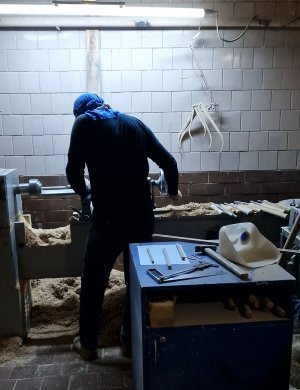
...made the blanks for me. From square pear wood blocks, I first drilled holes at the ends for the axes and then turned them into the required cylindrical shape. Three masts, the bowsprit, and one more part that I’ll discuss later.
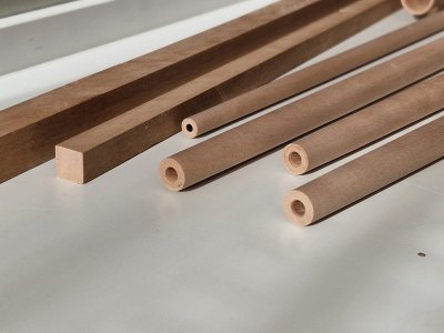
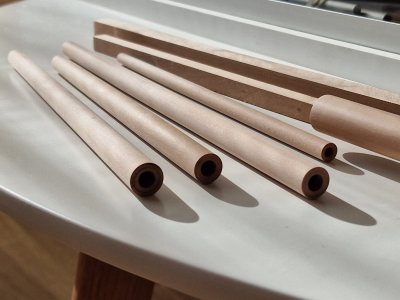
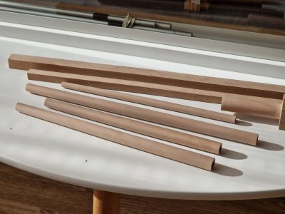
As promised, I will elaborate on my method for installing the spars (masts and bowsprit). Into the 6 cm deep holes at the ends of the blanks (on the side facing the hull), I inserted aluminum rods. Let’s use the bowsprit as an example to go over the setup.
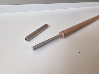
The diameter of the hole in the wooden cylinder is 6.2 mm, allowing a 6 mm rod to fit inside. Over this rod, a hollow spacer cylinder is placed, increasing the diameter to 8 mm.
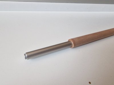
This diameter fits perfectly into the cylindrical tube (embedded piece) in the hull with an internal diameter of 8 mm.
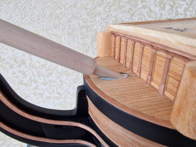
However, the bowsprit also requires a 30-degree angle cut.
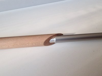
I created this angle using an angled sanding machine set to 30 degrees. Here's how it looks in its finished form.
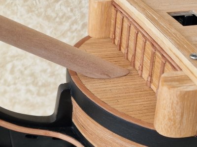
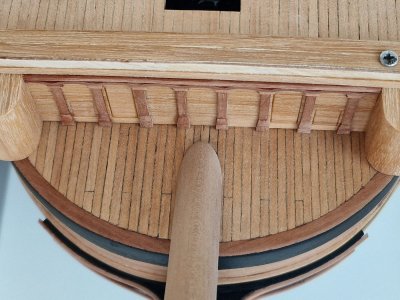
Everything fit perfectly, with no gaps and, most importantly, without lengthy adjustments.
The situation with the masts is similar but much simpler, as there’s no need to create an angle. However, I plan to add an anti-rotation system for the masts using square inserts, which I’ll discuss later.
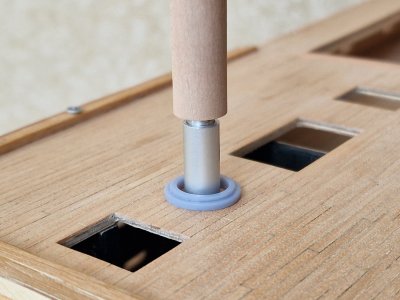
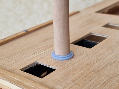
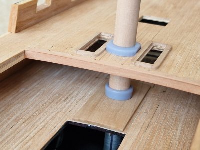
I also checked the 3D-printed rings for the masts. They are not painted yet, but it's already clear that they fit perfectly. I will go into detail about all the printed parts later. For now, we have 2.5 more parts to cover, focusing on the bow of the ship.
...
Let’s continue… For proper positioning of some details on the head of the ship, a bowsprit was needed. Until recently, an aluminum tube served this role, but I decided to make a wooden blank instead.
Realizing that creating a perfect cylinder with a taper at home was beyond my capabilities, I decided to find a turner. I found one online—a man who agreed to do the work for a reasonable price, and I’ll even show him…

...made the blanks for me. From square pear wood blocks, I first drilled holes at the ends for the axes and then turned them into the required cylindrical shape. Three masts, the bowsprit, and one more part that I’ll discuss later.


As promised, I will elaborate on my method for installing the spars (masts and bowsprit). Into the 6 cm deep holes at the ends of the blanks (on the side facing the hull), I inserted aluminum rods. Let’s use the bowsprit as an example to go over the setup.

The diameter of the hole in the wooden cylinder is 6.2 mm, allowing a 6 mm rod to fit inside. Over this rod, a hollow spacer cylinder is placed, increasing the diameter to 8 mm.

This diameter fits perfectly into the cylindrical tube (embedded piece) in the hull with an internal diameter of 8 mm.

However, the bowsprit also requires a 30-degree angle cut.

I created this angle using an angled sanding machine set to 30 degrees. Here's how it looks in its finished form.


Everything fit perfectly, with no gaps and, most importantly, without lengthy adjustments.
The situation with the masts is similar but much simpler, as there’s no need to create an angle. However, I plan to add an anti-rotation system for the masts using square inserts, which I’ll discuss later.


I also checked the 3D-printed rings for the masts. They are not painted yet, but it's already clear that they fit perfectly. I will go into detail about all the printed parts later. For now, we have 2.5 more parts to cover, focusing on the bow of the ship.
...
- Joined
- Jan 21, 2022
- Messages
- 886
- Points
- 403

I don't get it. Why would you put metal inside wooden dowels, are they not stiff enough?07.2024
Let’s continue… For proper positioning of some details on the head of the ship, a bowsprit was needed. Until recently, an aluminum tube served this role, but I decided to make a wooden blank instead.
Realizing that creating a perfect cylinder with a taper at home was beyond my capabilities, I decided to find a turner. I found one online—a man who agreed to do the work for a reasonable price, and I’ll even show him…
View attachment 483451
...made the blanks for me. From square pear wood blocks, I first drilled holes at the ends for the axes and then turned them into the required cylindrical shape. Three masts, the bowsprit, and one more part that I’ll discuss later.
View attachment 483454
View attachment 483455
View attachment 483456
As promised, I will elaborate on my method for installing the spars (masts and bowsprit). Into the 6 cm deep holes at the ends of the blanks (on the side facing the hull), I inserted aluminum rods. Let’s use the bowsprit as an example to go over the setup.
View attachment 483458
The diameter of the hole in the wooden cylinder is 6.2 mm, allowing a 6 mm rod to fit inside. Over this rod, a hollow spacer cylinder is placed, increasing the diameter to 8 mm.
View attachment 483460
This diameter fits perfectly into the cylindrical tube (embedded piece) in the hull with an internal diameter of 8 mm.
View attachment 483464
However, the bowsprit also requires a 30-degree angle cut.
View attachment 483465
I created this angle using an angled sanding machine set to 30 degrees. Here's how it looks in its finished form.
View attachment 483466
View attachment 483467
Everything fit perfectly, with no gaps and, most importantly, without lengthy adjustments.
The situation with the masts is similar but much simpler, as there’s no need to create an angle. However, I plan to add an anti-rotation system for the masts using square inserts, which I’ll discuss later.
View attachment 483468
View attachment 483469
View attachment 483470
I also checked the 3D-printed rings for the masts. They are not painted yet, but it's already clear that they fit perfectly. I will go into detail about all the printed parts later. For now, we have 2.5 more parts to cover, focusing on the bow of the ship.
...
It's not about rigidity, but about accuracy. At the time of forming the place for the masts, when I was building the hull, I did not have cylindrical wooden blanks and I could not implement the accuracy of the angles and perpendicularity of the masts. Therefore, I came up with such a scheme for the accuracy of the masts. Earlier in the review I talked about this in more detail.I don't get it. Why would you put metal inside wooden dowels, are they not stiff enough?
Details on how the masts were placed can be found here:I don't get it. Why would you put metal inside wooden dowels, are they not stiff enough?
https://shipsofscale.com/sosforums/...ed-with-john-mckays-anatomy.15458/post-403917
https://shipsofscale.com/sosforums/...ed-with-john-mckays-anatomy.15458/post-404410
In theory, it may be, but it is easier to make a perfectly even hole with a drill than to sharpen a perfectly even cylinder so that it goes inside without any play and does not jam.Ok. Now I understand. Wasn't it easier to taper dovel's ends on lathe?
07.2024
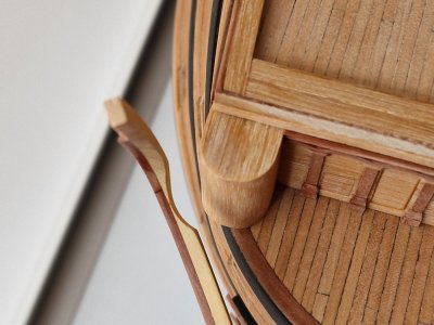
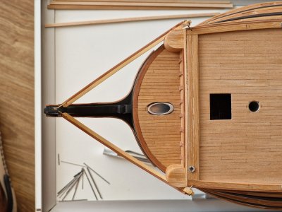
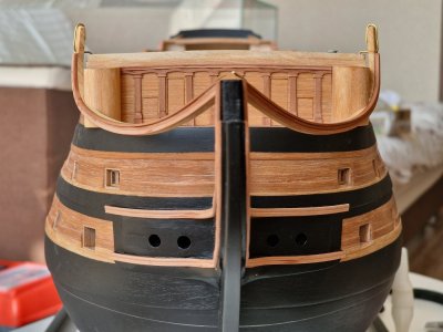
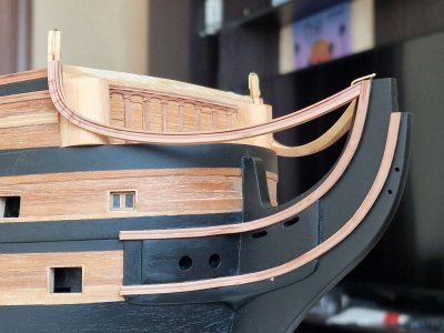
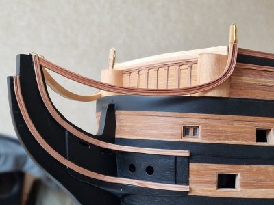
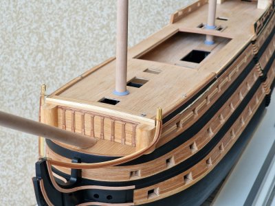
So, continuing the assembly diary... I got so carried away with making this part that I forgot to photograph the calculation process for it—the part that supports the entire head structure. The radius was too large to bend such a thick plank, and the only wide plank I had was made of gray boxwood. With no better option, I used it. I cut it according to a pre-calculated curve, which took a long time to determine because McKay's plans for the head structure had a significant error in the deck and superstructure. I’ve written about this earlier.
As a result, the curve of this part was adjusted through trial fittings and modifications. Moreover, in the plans, this part was only shown from the top, bottom, and side views, but its diagonal dimensions were not provided. So, the design had to be visualized from a perspective not included in the plans. For reference, I used drawings from another source, adjusting the curvature to fit my dimensions.
Ultimately, I glued a decorative plank onto the boxwood arc and bent it where possible. For areas where the radius was too tight, I created a composite structure. I understand this approach isn’t entirely accurate to the anatomy, but replicating the original method wasn’t feasible for me. So, I improvised. On the left side, by the way, it’s coated with oil, and any traces of superglue are invisible—only the wood joints are visible, as I mentioned earlier.
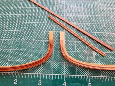
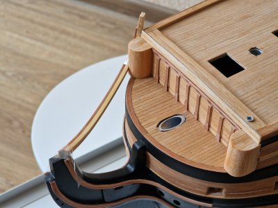
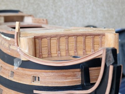
The process was further complicated by the need to fit this part to the midshipmen's toilets. However, in the end, I was very pleased with the result. It turned out symmetrical, and finally, something is starting to take shape.
This is just an intermediate result. Up next are the grates of the head... and then only two more parts will remain before I catch up to the present.

So, continuing the assembly diary... I got so carried away with making this part that I forgot to photograph the calculation process for it—the part that supports the entire head structure. The radius was too large to bend such a thick plank, and the only wide plank I had was made of gray boxwood. With no better option, I used it. I cut it according to a pre-calculated curve, which took a long time to determine because McKay's plans for the head structure had a significant error in the deck and superstructure. I’ve written about this earlier.
As a result, the curve of this part was adjusted through trial fittings and modifications. Moreover, in the plans, this part was only shown from the top, bottom, and side views, but its diagonal dimensions were not provided. So, the design had to be visualized from a perspective not included in the plans. For reference, I used drawings from another source, adjusting the curvature to fit my dimensions.
Ultimately, I glued a decorative plank onto the boxwood arc and bent it where possible. For areas where the radius was too tight, I created a composite structure. I understand this approach isn’t entirely accurate to the anatomy, but replicating the original method wasn’t feasible for me. So, I improvised. On the left side, by the way, it’s coated with oil, and any traces of superglue are invisible—only the wood joints are visible, as I mentioned earlier.


The process was further complicated by the need to fit this part to the midshipmen's toilets. However, in the end, I was very pleased with the result. It turned out symmetrical, and finally, something is starting to take shape.


This is just an intermediate result. Up next are the grates of the head... and then only two more parts will remain before I catch up to the present.

- Joined
- Dec 3, 2022
- Messages
- 1,547
- Points
- 488

That parts have some very nice natural flowing curves, Sergey.07.2024
So, continuing the assembly diary... I got so carried away with making this part that I forgot to photograph the calculation process for it—the part that supports the entire head structure. The radius was too large to bend such a thick plank, and the only wide plank I had was made of gray boxwood. With no better option, I used it. I cut it according to a pre-calculated curve, which took a long time to determine because McKay's plans for the head structure had a significant error in the deck and superstructure. I’ve written about this earlier.
As a result, the curve of this part was adjusted through trial fittings and modifications. Moreover, in the plans, this part was only shown from the top, bottom, and side views, but its diagonal dimensions were not provided. So, the design had to be visualized from a perspective not included in the plans. For reference, I used drawings from another source, adjusting the curvature to fit my dimensions.
Ultimately, I glued a decorative plank onto the boxwood arc and bent it where possible. For areas where the radius was too tight, I created a composite structure. I understand this approach isn’t entirely accurate to the anatomy, but replicating the original method wasn’t feasible for me. So, I improvised. On the left side, by the way, it’s coated with oil, and any traces of superglue are invisible—only the wood joints are visible, as I mentioned earlier.
View attachment 483641
View attachment 483642
View attachment 483643
The process was further complicated by the need to fit this part to the midshipmen's toilets. However, in the end, I was very pleased with the result. It turned out symmetrical, and finally, something is starting to take shape.
View attachment 483644
View attachment 483645
View attachment 483646
View attachment 483647
View attachment 483648
View attachment 483649
This is just an intermediate result. Up next are the grates of the head... and then only two more parts will remain before I catch up to the present.

Regards, Peter
Clever, very clever.

Friends, thank you. Yes, when there are no detailed drawings, you have to improvise) but it's fun))That parts have some very nice natural flowing curves, Sergey.
Regards, Peter
Fantastic stuff, your work, the pictures, and how you explain everything. Thanks for taking the time to show all this Serikoff.
T
True storyClever, very clever.


