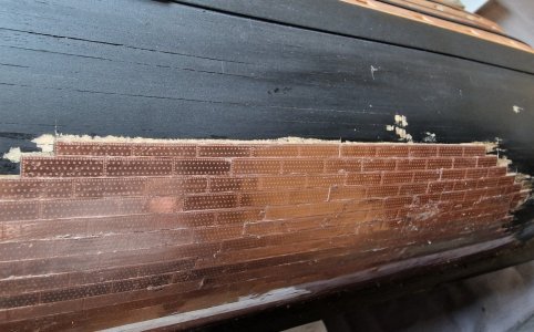
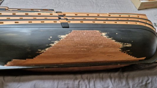
HMS Victory [1805] 1:79 by serikoff. Started with Mantua -> Upgraded with John McKay's Anatomy.

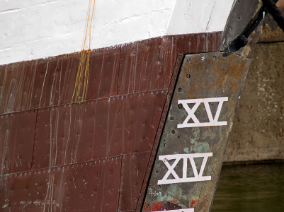
Copper was laid from the stern to the bow (you remember that) and from the waterline to the keel
Thanks for your post Iutar. You are correct and this has been discussed a few times lately here at SoS. Your photos are more pieces of evidence that this is how it was done. From the build logs it seems more than half the hulls are incorrectly coppered from the keel up instead of how it was done on a real ship, from the water line down, for the reasons you explained very clearly.
Allan
 
Last edited:
excuse me , do you have any source information regarding coppered hull protection? Thank you , Frank
Sorry, I do not have primary sources, but found a lot of different information in my books. I don’t copper my models because I like to show the frames, so I didn’t any further research for this.
 
I think for my needs the information that is available is enough. I am not making a model for a competition, museum or exhibition. For my modest needs the anatomy of my ship is enough and also the anatomy of similar ships...


... but I also join the question, since it is still interesting to know the different options.
my question is to ask if you have more any information about it.Thank you for answering me.Frank
 
from the water line down

Allan, good afternoon!
This was done in other countries as well.
The Americans in their young fleet did the same as the British once did:
There is even an old painting that everyone has seen and knows, but no one looked closely at. Craftsmen install copper sheets from the waterline to the keel, that is, from top to bottom.

img_gt08n1018435140.jpg

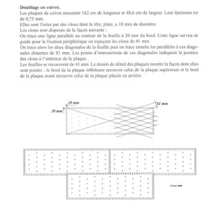
The French also installed copper sheets according to the same principles as the British.

медь французск.jpg

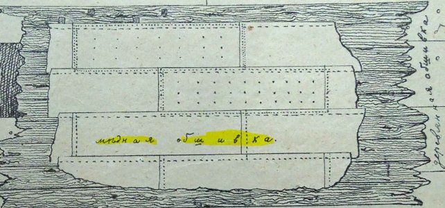
This is what they did in Russia:

орпппа.JPG

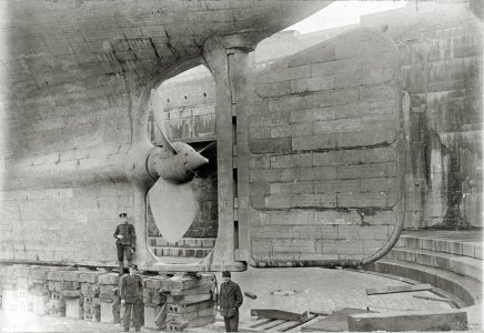
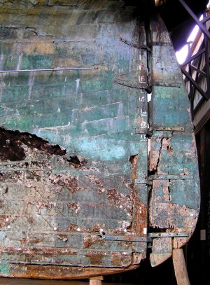
In modern times, despite various options, the basic scheme has not changed for centuries:

03 (24).jpg

2ф.jpg

image.png.2250d1ff1296aff36af3b353814ef356.png
 
I don’t copper my models because I like to show the frames,
I am in agreement with you regarding coppering. It is not so much the work that is required, but I personally am not fond of the look. Open framing or planked I hope I will not be building another model of a ship from 1780's and beyond unless the client requires such.
Allan
 
Thanks for your post Iutar. You are correct and this has been discussed a few times lately here at SoS. Your photos are more pieces of evidence that this is how it was done. From the build logs it seems more than half the hulls are incorrectly coppered from the keel up instead of how it was done on a real ship, from the water line down, for the reasons you explained very clearly.
Allan
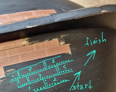
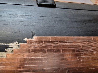
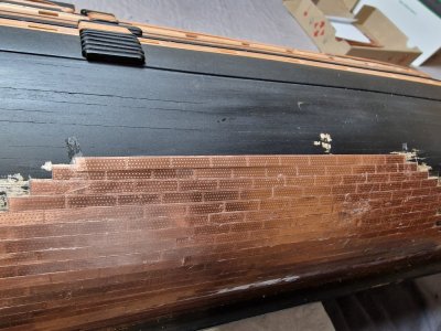
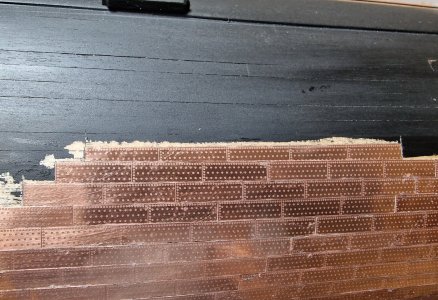
I cover from the bottom up because it simplifies the task and to achieve horizontal correct lines. Imitation of nails is done by the drawing on the copper facing. And since I glue in a butt and not in an overlap, then it makes no difference how the copper is glued, the correctness of gluing in this case will be shown by the drawing of the nails. But if you glue in an overlap, then there are no options, only in the right way. I wrote about this at the very beginning.
 
Copper... and ones more copper.


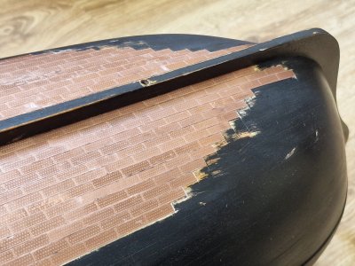
With experience, the work is progressing faster. The same routine continues: rough sanding on the inside, polishing to a shine on the outside, cutting into strips, taping them with scotch tape, and then fixing them in place.

HMS Victory 713.jpg

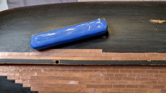
To press the copper strip against the hull while the glue sets, I came up with this tool. It’s made from air-drying plasticine (available in toy stores). I rolled it into a “sausage” and pressed one side flat against the table to create a flat surface. After it hardened, I applied tape to the flat side to prevent glue from sticking to the plasticine.

HMS Victory 714.jpg

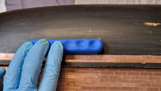
On the other side, I made indentations for my fingertips to better grip and stabilize the tool when pressing the copper strip down.

HMS Victory 715.jpg

This way, I apply even pressure across the entire surface, not just at the points where my fingers touch. I replace the tape occasionally when it accumulates too much glue.
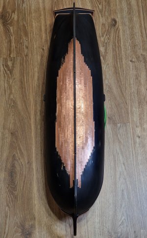
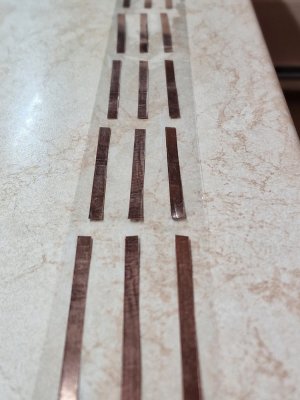
I’m working symmetrically and alternately. First, I glued half of a sheet on one side of the hull, and now I’m applying the other half to the opposite side. So far, I’ve used one of the six sheets of copper plating. The downside is that every sheet has defects. One strip not only lacks the row of nail details but is also wider than the others. Because of this, I set aside one defective and one normal strip (from the other side) to use later for the triangular sections.

HMS Victory 716.jpg

I really hope the six sheets will be enough for the entire hull.
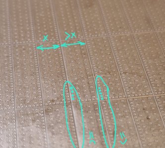
I also wanted to demonstrate the correct alignment of the nail pattern and reiterate that if plating overlaps, you should start at the stern and work downward toward forward the keel. However, if the plating is applied edge-to-edge, the nail pattern alone determines the proper orientation, meaning you can start from anywhere as long as the nail pattern aligns correctly. Starting from the keel is simply more convenient for maintaining horizontal lines.

HMS Victory 717.jpg

Another time-consuming part is cleaning the edges of each copper strip after it’s glued, to ensure the next strip fits seamlessly edge-to-edge. The glue seeps out from under the copper when I press it down, and I have to remove the excess with a scalpel. Some of the glue, stained with paint, also seeps through the seams, but this will be cleaned up after the tape is removed and the final polishing is done.

HMS Victory 718.jpg

So, 1/6 is complete...

HMS Victory 719.jpg

...and there are five more rounds of this dance to go. But for now, this is the easy part. Things will get more interesting when I start dealing with wedges and triangular sections!

P.S. A big thank you to everyone who has shown such great interest and attention to my build, as well as for all the numerous likes from you!!! ThumbsupFirst Place Metal

...
 
Last edited:
Copper... and ones more copper.


With experience, the work is progressing faster. The same routine continues: rough sanding on the inside, polishing to a shine on the outside, cutting into strips, taping them with scotch tape, and then fixing them in place.

View attachment 490432

To press the copper strip against the hull while the glue sets, I came up with this tool. It’s made from air-drying plasticine (available in toy stores). I rolled it into a “sausage” and pressed one side flat against the table to create a flat surface. After it hardened, I applied tape to the flat side to prevent glue from sticking to the plasticine.

View attachment 490436

On the other side, I made indentations for my fingertips to better grip and stabilize the tool when pressing the copper strip down.

View attachment 490437

This way, I apply even pressure across the entire surface, not just at the points where my fingers touch. I replace the tape occasionally when it accumulates too much glue.
I’m working symmetrically and alternately. First, I glued half of a sheet on one side of the hull, and now I’m applying the other half to the opposite side. So far, I’ve used one of the six sheets of copper plating. The downside is that every sheet has defects. One strip not only lacks the row of nail details but is also wider than the others. Because of this, I set aside one defective and one normal strip (from the other side) to use later for the triangular sections.

View attachment 490438

I really hope the six sheets will be enough for the entire hull.
I also wanted to demonstrate the correct alignment of the nail pattern and reiterate that if plating overlaps, you should start at the stern and work downward toward forward the keel. However, if the plating is applied edge-to-edge, the nail pattern alone determines the proper orientation, meaning you can start from anywhere as long as the nail pattern aligns correctly. Starting from the keel is simply more convenient for maintaining horizontal lines.

View attachment 490439

Another time-consuming part is cleaning the edges of each copper strip after it’s glued, to ensure the next strip fits seamlessly edge-to-edge. The glue seeps out from under the copper when I press it down, and I have to remove the excess with a scalpel. Some of the glue, stained with paint, also seeps through the seams, but this will be cleaned up after the tape is removed and the final polishing is done.

View attachment 490440

So, 1/6 is complete...

View attachment 490441

...and there are five more rounds of this dance to go. But for now, this is the easy part. Things will get more interesting when I start dealing with wedges and triangular sections!

P.S. A big thank you to everyone who has shown such great interest and attention to my build, as well as for all the numerous likes from you!!! ThumbsupFirst Place Metal

...
Very nice progress, Sergey! Copper hulls aren't my thing, but I would affirm that for this ship it must be done. Not overlapping the plates has done a nice job preserving scale. Bravo!
 
Very nice progress, Sergey! Copper hulls aren't my thing, but I would affirm that for this ship it must be done. Not overlapping the plates has done a nice job preserving scale. Bravo!
I then tried it on a sample, it was possible to do it with an overlap, but I can imagine how difficult and longer it is. That's why I'm glad that I started doing edge to edge. One thing I'm worried about is that the surface is smooth, otherwise, if it's bumpy, then I'll definitely have to patinated it in any way.
 
Progress keeps progressing, and there's more and more copper on the ship.

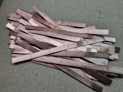
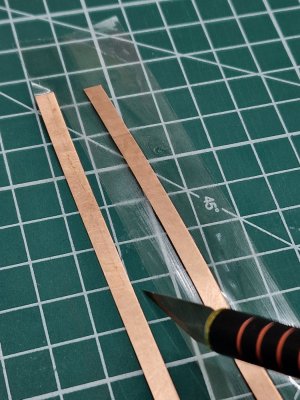
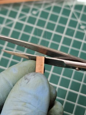
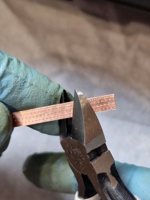
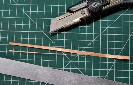
I also wanted to share how I protect the copper with tape and, most importantly, how I cut it. Here's the step-by-step process:

After cutting the copper strips, I hang a piece of tape and stick the strips onto it. I do this for all the strips at once to ensure they oxidize uniformly — or rather, don’t oxidize.

HMS Victory 720.jpg

Then I hang these "garlands" so that they don't stick together and, when I have time, I cut out copper strips from scotch tape.
To cut them, I place the strips with the non-adhesive side down on a cutting mat. Using a very sharp scalpel, I carefully trim the tape along the edge of the copper strip.

HMS Victory 721.jpg

For convenience, I cut the ends of the tape with scissors, ensuring the adhesive side remains on top. This way, the edge aligns perfectly with the copper.

HMS Victory 722.jpg

On-site, I cut the necessary number of pieces (from 1 to 5) from a strip of 10 plates using sharp snippers.

HMS Victory 723.jpg

Today, I also tackled my first wedge!

First, I placed a long strip over the plating and marked the triangular section to be cut.

HMS Victory 724.jpg
HMS Victory 725.jpg

Then, I trimmed the excess with a scalpel and ruler (I save the leftover piece since it may come in handy for a wedge of similar size later).

HMS Victory 726.jpg

Finally, I cut the strip into segments and glued them in place.

HMS Victory 727.jpg
HMS Victory 728.jpg

Working with wedges will be the most challenging part of the plating process. Not only do I need to calculate the correct lines and maintain symmetry on both sides, but I also need to ensure that the nail pattern always imitates proper overlap (more on that later).

For now, I’m almost at the RDK. There are two upper rows left, but first, I’ll make everything symmetrical on the other side and use that as a reference for the next steps. Wish me luck!

HMS Victory 729.jpg

P.S. You know, even at this stage, you can start to see the big picture, and it feels like all this effort is worth it.

UPD: I found a way to speed up the process of naming stripes even more! It's further down this thread.
...
 
Last edited:
Hello,
I hadn't read this excellent post by SERIKOFF for a while.
The subject of copper lining is fascinating.
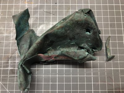
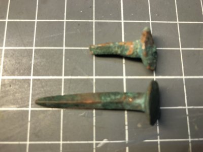
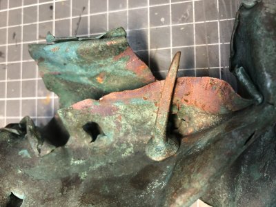
I thought it might be interesting to show you my find on a pebble beach near my home.It's a fragment of copper plate with two nails that remained inserted.

IMG_3399.JPGIMG_3406.JPGIMG_3410.JPG
 
You are absolutely right in your statements. The only thing is that many still consider it cheating or deception, but this is their right. I like wood more than plastic, but ... as I already said, to make a lot of repeatable parts well, you need machines, which I do not have. Doing 100500 columns by hand is a pain)) That's why I make everything from wood except for those parts that are under paint and of which there are many. Plus, I like modeling and this is also a hobby, so I do not understand those who have a bad attitude to 3D. The same can be said about milling parts on a milling machine, then this is cheating, or if it is wood, then it is possible?)) It turns out to be double standards. You are doing the right thing by trying to do everything yourself from wood, this is very commendable. But I think that when your skills improve, you will want to speed up the construction process a little)) Thank you for your comment, I will be glad if you continue to follow the construction. If you have any questions, please contact me.
For me, the use of computer design and then 3D printing as well as laser engraving is a modern evolution of modeling.
I understand the modelers who defend the work of all wood, there are great artists, but making pieces with these modern tools also requires other skills that make the work just as magnificent.
Bravo SERIKOFF
 
Progress keeps progressing, and there's more and more copper on the ship.

I also wanted to share how I protect the copper with tape and, most importantly, how I cut it. Here's the step-by-step process:

After cutting the copper strips, I hang a piece of tape and stick the strips onto it. I do this for all the strips at once to ensure they oxidize uniformly — or rather, don’t oxidize.

View attachment 490674

Then I hang these "garlands" so that they don't stick together and, when I have time, I cut out copper strips from scotch tape.
To cut them, I place the strips with the non-adhesive side down on a cutting mat. Using a very sharp scalpel, I carefully trim the tape along the edge of the copper strip.

View attachment 490675

For convenience, I cut the ends of the tape with scissors, ensuring the adhesive side remains on top. This way, the edge aligns perfectly with the copper.

View attachment 490676

On-site, I cut the necessary number of pieces (from 1 to 5) from a strip of 10 plates using sharp snippers.

View attachment 490679

Today, I also tackled my first wedge!

First, I placed a long strip over the plating and marked the triangular section to be cut.

View attachment 490680
View attachment 490681

Then, I trimmed the excess with a scalpel and ruler (I save the leftover piece since it may come in handy for a wedge of similar size later).

View attachment 490682

Finally, I cut the strip into segments and glued them in place.

View attachment 490683
View attachment 490684

Working with wedges will be the most challenging part of the plating process. Not only do I need to calculate the correct lines and maintain symmetry on both sides, but I also need to ensure that the nail pattern always imitates proper overlap (more on that later).

For now, I’m almost at the RDK. There are two upper rows left, but first, I’ll make everything symmetrical on the other side and use that as a reference for the next steps. Wish me luck!

View attachment 490685

P.S. You know, even at this stage, you can start to see the big picture, and it feels like all this effort is worth it.

...
Good afternoon Sergey. Thanks for sharing your process. I always learn a lot from your posts. Good progress with those plates only a gazzilion to go ;). Cheers Grant
 
Progress keeps progressing, and there's more and more copper on the ship.

I also wanted to share how I protect the copper with tape and, most importantly, how I cut it. Here's the step-by-step process:

After cutting the copper strips, I hang a piece of tape and stick the strips onto it. I do this for all the strips at once to ensure they oxidize uniformly — or rather, don’t oxidize.

View attachment 490674

Then I hang these "garlands" so that they don't stick together and, when I have time, I cut out copper strips from scotch tape.
To cut them, I place the strips with the non-adhesive side down on a cutting mat. Using a very sharp scalpel, I carefully trim the tape along the edge of the copper strip.

View attachment 490675

For convenience, I cut the ends of the tape with scissors, ensuring the adhesive side remains on top. This way, the edge aligns perfectly with the copper.

View attachment 490676

On-site, I cut the necessary number of pieces (from 1 to 5) from a strip of 10 plates using sharp snippers.

View attachment 490679

Today, I also tackled my first wedge!

First, I placed a long strip over the plating and marked the triangular section to be cut.

View attachment 490680
View attachment 490681

Then, I trimmed the excess with a scalpel and ruler (I save the leftover piece since it may come in handy for a wedge of similar size later).

View attachment 490682

Finally, I cut the strip into segments and glued them in place.

View attachment 490683
View attachment 490684

Working with wedges will be the most challenging part of the plating process. Not only do I need to calculate the correct lines and maintain symmetry on both sides, but I also need to ensure that the nail pattern always imitates proper overlap (more on that later).

For now, I’m almost at the RDK. There are two upper rows left, but first, I’ll make everything symmetrical on the other side and use that as a reference for the next steps. Wish me luck!

View attachment 490685

P.S. You know, even at this stage, you can start to see the big picture, and it feels like all this effort is worth it.

...
Hi Sergey
Nice progress on the hull coppering
COngrats
 
Hello,
I hadn't read this excellent post by SERIKOFF for a while.
The subject of copper lining is fascinating.
I thought it might be interesting to show you my find on a pebble beach near my home.It's a fragment of copper plate with two nails that remained inserted.

View attachment 490746View attachment 490747View attachment 490748
Wow, that's really cool!! Not only do you live close to the places where you can find it, but the find is also very authentic! How long could it have been lying there, and what is the history of this vessel, very interesting! Thanks for showing.

For me, the use of computer design and then 3D printing as well as laser engraving is a modern evolution of modeling.
I understand the modelers who defend the work of all wood, there are great artists, but making pieces with these modern tools also requires other skills that make the work just as magnificent.
Bravo SERIKOFF
Thank you for your understanding and your point of view, I fully support it. To speed up the process of completing the project, I am going to all options... I have been building this ship for a very long time. I am not in a hurry, of course, and I do not do it just to finish, but where there is an opportunity to speed up the process, I do it. I already have an idea for a new ship... I am clearly fired up by the idea, but for now I need to weigh all the pros and cons and make a decision. Thank you for your comment.

Good afternoon Sergey. Thanks for sharing your process. I always learn a lot from your posts. Good progress with those plates only a gazzilion to go ;). Cheers Grant
Thank you for your words! It's very nice that it's useful to someone. There's still a lot left, of course, but thank you for encouraging me)))

Hi Sergey
Nice progress on the hull coppering
COngrats
Thank you)) I try))
 
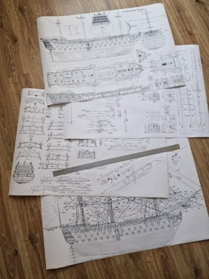
I just had your four plans that you kindly made available to us printed in A0 by a professional reprographer.
They are superb and practically at the 1/78 scale of our VICTORY MANTUA.
It's been a long time since I used the plans from the 1970 kit and I did the scale conversions with McKAY's book.
If you have made other pages, it could be interesting.
Thank you for all the time you spend showing us and explaining your progress on your magnificent VICTORY.

HMS Victory 191.jpg
 
I just had your four plans that you kindly made available to us printed in A0 by a professional reprographer.
They are superb and practically at the 1/78 scale of our VICTORY MANTUA.
It's been a long time since I used the plans from the 1970 kit and I did the scale conversions with McKAY's book.
If you have made other pages, it could be interesting.
Thank you for all the time you spend showing us and explaining your progress on your magnificent VICTORY.

View attachment 490943
When I printed out the Mantua plans, I changed the size a little, and when I recalculated the scale, it turned out to be 1:79. This is really very close to 1:78. And at the time of construction, I only needed those views from McCoy's plans that I compiled on these 4 plans. Unfortunately, there is nothing else except these 4 sheets. I was glad to help. If necessary, I can post a file from Photoshop, where I scaled it all. And if you have scans, you can add them and scale them to the finished ones.
 
Back
Top