- Joined
- Jul 6, 2020
- Messages
- 8
- Points
- 33

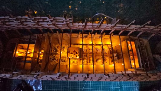
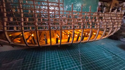
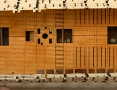
I believe they are vent trunks. Not a 100% sure though.
 |
As a way to introduce our brass coins to the community, we will raffle off a free coin during the month of August. Follow link ABOVE for instructions for entering. |
 |
 |
The beloved Ships in Scale Magazine is back and charting a new course for 2026! Discover new skills, new techniques, and new inspirations in every issue. NOTE THAT OUR FIRST ISSUE WILL BE JAN/FEB 2026 |
 |


Allan,Thank you kindly Dominic,
Looking at a number of contemporary drawings and contracts I can't find these anywhere, so far .I was just curious to know what these various blocks were not having seen them before and it is not really important in the end as it will likely all be covered up never to be seen again.
Allan


Hallo.Hallo Dominic,
das sieht schon mal gut aus!!! Weiter so. Ich bin gespannt, wie es weitergeht.
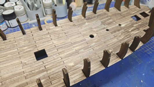
Frage: Die Terrassenverbindungen auf dem 2. Bild sehen etwas seltsam aus, als ob die Dielen höher wären. Gibt es beim Zusammenfügen der Terrassen einen Überhang der Dielen? Kann man das verbessern oder muss man damit leben?
Beste grüße
Günther Schiff-1
PS: Ich hoffe, Sie verstehen, was ich meine?


Yes normally when I am working with multi-part decks, that need to be planked anyway, I work the planks in so the joint ends up being invisible.Hey Dominc,
thanks for your reply and I understood everything you said. Great!
You can't see it in the bottom section. But when you have built the upper decks. It's a strange solution that AL has done with the decks. I don't have a solution at hand right now either. I'd have to think about something. Great pictures and I wish you continued success. I'll stay tuned to your build report and look forward to new pictures.
Best regards
Günther

