HMS Victory - Caldercraft-Jotika - 1/72. Build log

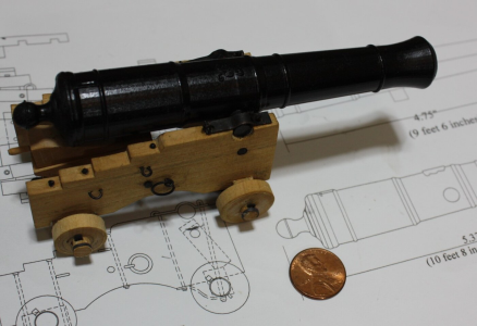
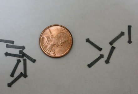
Regarding the gun port hardware, it may not be necessary for some kits as they generally supply the hinge work, but these are easily 3D printed if you are not satisfied with the sizes and shape of the hinges provided. The ones I had done included the head of the bolts. The ones in the photo below are for late 17th century British ships at 1:64 and include both right hand and left hand pieces. Some are upside down in the photo but the offset hinge part at the top of the plate can be seen. I do worry that too many resin parts are a negative, in my own mind that is, but there is no way to tell by just looking at them. To each his own. I also show Spanish pattern cannon circa 1718 in two different scales. The cannon were printed in grey by a friend, but I would go with black resin in the future. Better than painting :)
Allan

hinges.JPG3D printed cannon 1 to 64  and 1 to 24.JPG
 
Thank you all (Byrian, Uwe, Grant, Allan, Paul, Mike and Günter). Your English is just fine Günter. I understand perfectly and best of luck with your Victory. Have you a Build Log?

Allan, thanks again for your comments regarding the wales. As I said before, this is not something I had allowed for (as the instructions do not allude to the rabbett allowing for the wales thickness). It is a good point however and something which builders of any ship should be aware of not just Victory.

On another issue Allan, as you know, I have used your cannon STL files to have 70 gun barrels created by a 3D printing service, here in Australia. Well, the product has arrived and production was very fast. The product quality is excellent with correct barrel length for my 1/72 scale and in black plastic which negates the need for painting. Cost worked out (including delivery), at about A$0.82 per gun - Not expensive. Below is an image of the made barrels, along with some of the brass equivalents included in the Caldercraft kit.

View attachment 466535
You will note in the picture above, that:

- The cannon barrels have the trunnion correctly located and off centre from the centreline of the barrel
- The cascable (the ring) at the rear of the cannon is correctly located and of the required size for the breeching tackle
- There is a 'touch' hole' or vent over the breech which I wasn't aware of in the file - A bonus.
- The Royal Crest on the barrels is present (see below), but it is hard to see as it is black on black. I think I may need to 'dry brush/paint' these with a grey to highlight them.

View attachment 466536

However, a problem - You can see in the picture, that the 3D building of plastic resin along and around the barrels has left a 'rippling' as it builds up the cannon. You only see it when you are 'up close' so it may not be such a problem as is obvious in the above image. Also, the plastic is relatively shiny, and definately not a matt finish. I am going to have to deal with these issues somehow.

One thing I have tried and it seems effective, is to spay the barrel with a matt varnish finish. I have used Testors spray matt finish and it appears to infill the rippling 'lows' and evens out the surface, as well as reduces the shininess to be a matt appearance. This may be my answer. I certainly could not sand or try and remove the rippling as it would destroy the detail of the crest and the ring reinforcing etc.

This barrel production was always ever an experiment, and thanks to Allan, I have been able to carry it through without too much expense. The 3D printing has produced an enhanced and more detailed product, but with the downside of the 'rippling' surface appearance. I still have the kit-provided brass barrels which will have:

- To have the trunnions added
- No Royal Crest
- No cascable at the breech
- No blacking so would need some brass blackening treatment

So if I can hide the rippling, the made 3D barrels will be superior. Many thanks again Allan.

Best Regards,

PeterG
@Model Monkey we need your valuable experience. Can you identify the problem as to why this 'ripple' was printed? Is this the quality of the printer, the printing medium used, or a combination of both? :)
 
@Model Monkey we need your valuable experience. Can you identify the problem as to why this 'ripple' was printed? Is this the quality of the printer, the printing medium used, or a combination of both? :)
The cannon's rippling is a characteristic typical of FDM printing. FDM is a 3D printing process that uses a continuous filament of a melted thermoplastic material extruded through a nozzle.

The cannon design is excellent and would benefit from printing using a resin printer based on SLA or LCD technology for a much smoother surface. SLA and LCD printers create layers by exposing liquid resin in a tank to UV light. The process is more expensive than FDM but the results are normally far superior to FDM for scale models.

When printing cannons using SLA or LCD technology, I recommend printing the cannons vertically, muzzle down toward the build plate, for the smoothest surface possible.

Hope this helps.
Many thanks, Steve. I knew we would have an answer!
 
Many thanks for the comments regarding the 3D Printing of the cannons. I have contacted the Australian service who have provided the 3D cannons, and in particular, drew their attention to Steve Larsen's (Magic Monkey) post # 143. At this stage the service (called CraftCloud), have not gotten back to me but it will be interesting to see what they have to say. Thank you Jimsky for reaching out to Steve.

While the cannon printing issue bubbles along, I have had to move on to more routine build matters and I am up to the much-feared and dreaded 'coppering'. This is the next item to tackle in the Instructions Manual and although I have spent some time adding ring-bolts and eyes to the bulwarks, this is only a 'time-filler' in delaying the coppering.

I have looked at the approach to the coppering from a range of different perspectives. I have seen some posts which advise against coppering at all (and leave the pristine copper second planking as the outer appearance. I have opted more towards the true likeness to the ship and so have decided to go ahead and add the 2,500-odd copper plates as provide in the kit. There are issues with this, for example, some say there should be overlap of plates (as this is as the ship had them applied), some say start at the stern and populate them moving forward, and the Instruction Manual says start at the keel and move towards the keel.

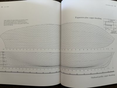
In McGowan's book ('HMS Victory, Her Construction, Career and Restoration'), the following diagram details the coppering pattern:

Img_2112.jpg

While this pattern of copper plates appears accurate, it is a difficult one to model as the number of plates required to be trimmed along the waterline is huge!!! Obviously trimming plates and creating a sharp waterline across a large number of plates will be hard, despite an edge covering of black tape (as recommended).

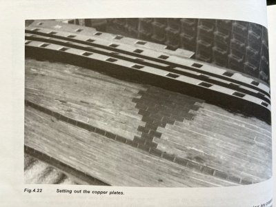
I have also a copy of 'The New Period Ship Handbook' by Keith Julier, which details an alternative coppering approach where the plates are laid along the waterline and then down towards the keel such that the majority of shaped plates will then be in areas of the hull which are relatively hidden and so any mistakes are more obscure. This seemed to be a better way forward although not as accurate in replicating the actual ship. The picture referred to in Julier's book is as below:

Julier.jpg

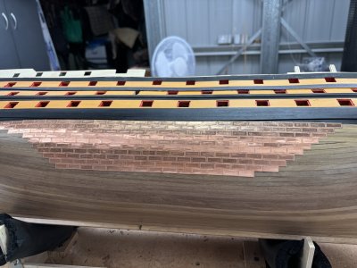
So with some Gel Super Glue and a shaking hand, off I go into placing these plates as best I can. A couple of images follow:

IMG_2109.JPG

I have painted a clear water-based varnish to the underside walnut finished planking and this seems to be holding the Gel Super Glue (Gel CA) very well. The Gel allows about 10 seconds of movement before it 'grabs' but when it does, a scalpel is the only way to then release an incorrectly placed copper plate. There a quite a few 'errors' and repositioning being required!!

IMG_2111.JPG

Overall I am happy with the way it is going and I am going to use quite a few tubes of Gorilla Gel Super Glue, but that stuff is GOOD.

As I proceed there is invariably a little bit of 'over glue' and some seaps out the side if I apply too much. I then wipe it away but on some plates some residue may remain. Does anyone know hoe to remove dried residue or a smear of Super Glue once its applied? Ultimately I want to spray the coppering with matt varnish, but a good clean of these smears would be preferable first.

Best regards,

PeterG

Elapsed Time = 960 hours
 
WoW your build is coming on great, I have been building this same kit for 10 years from starting it as a complete novice and it being my first build it's not up to the standards of yours and others on this forum and was a little ambitious for a first build. I have a little way still to go on the rigging mainly but it will get finish next year with a little luck. On my next build I will take on board some of your tips and techniques and with the little experience I have picked up may be able to achieve some of the high standards yours and others are showing. Keep up the great work, it all ready puts mine to shame. I will follow along to see how it turns out.
Great work so far.
 
I have spent an evening reading your Victory posts, and am inspired! I think that I know what my next build will be if She Who Must Be Obeyed agrees.
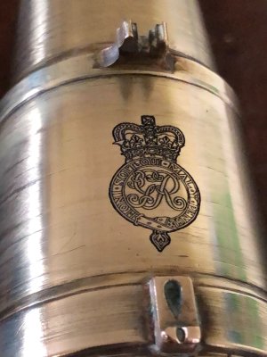
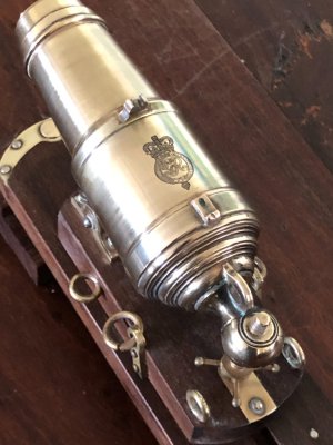
The photos show George 3 cyphers lasered into 2 guns, which I made in brass. The first is a 32pr carronade and the second is a 24pr long gun. Those cyphers are approx 16 x 10mm. The lasering process takes about 2 minutes at this size. I have a friend who has a 30w fiber laser which is what is required to obtain a deep cut image which will not disappear with polishing or lacquering.

George3 Cypher1.JPG

Goerge3 cypher3.JPG

IMG_3717.JPG

George3 cypher1.JPG
 
Very nice John. Those are beautiful. As well as your copper plating is Peter. Both absolutely beautiful work.

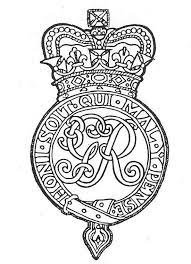
John, would you a jpeg, bmp, png image of the George 3 cyphers. Or maybe a STL, OBJ, SVG file of it? I've sketched a 3D ships door in Fusion 360. I've been searching the internet for a crown image to place on the lower panel of the door.
 
Last edited:
Very nice John. Those are beautiful. As well as your copper plating is Peter. Both absolutely beautiful work.

John, would you a jpeg, bmp, png image of the George 3 cyphers. Or maybe a STL, OBJ, SVG file of it? I've sketched a 3D ships door in Fusion 360. I've been searching the internet for a crown image to place on the lower panel of the door.
George 3 cyphers. From memory, the first one was for iron guns, the second for bronze.

George 3 cypher.jpg

George 3 cypher bronze.jpg
 
The photos show George 3 cyphers lasered into 2 guns, which I made in brass.
These brass cannon barrels are fabulous. The second photo really caught my eye as this is the best Armstrong Frederick pattern gun I have ever seen made in brass. Including the chase astragal ring with fillets and the button ring is wonderful to see. All I can say is WOW.
Allan
 
Last edited:
Congratulations on your meticulous work! Your attention to detail is truly impressive, and I can't wait to see how the rest of the project unfolds. Keep up the great work, I will follow the progress with much pleasure. Pouce en l'air;)
 
Thank you all (Byrian, Uwe, Grant, Allan, Paul, Mike and Günter). Your English is just fine Günter. I understand perfectly and best of luck with your Victory. Have you a Build Log?

Allan, thanks again for your comments regarding the wales. As I said before, this is not something I had allowed for (as the instructions do not allude to the rabbett allowing for the wales thickness). It is a good point however and something which builders of any ship should be aware of not just Victory.

On another issue Allan, as you know, I have used your cannon STL files to have 70 gun barrels created by a 3D printing service, here in Australia. Well, the product has arrived and production was very fast. The product quality is excellent with correct barrel length for my 1/72 scale and in black plastic which negates the need for painting. Cost worked out (including delivery), at about A$0.82 per gun - Not expensive. Below is an image of the made barrels, along with some of the brass equivalents included in the Caldercraft kit.

View attachment 466535
You will note in the picture above, that:

- The cannon barrels have the trunnion correctly located and off centre from the centreline of the barrel
- The cascable (the ring) at the rear of the cannon is correctly located and of the required size for the breeching tackle
- There is a 'touch' hole' or vent over the breech which I wasn't aware of in the file - A bonus.
- The Royal Crest on the barrels is present (see below), but it is hard to see as it is black on black. I think I may need to 'dry brush/paint' these with a grey to highlight them.

View attachment 466536

However, a problem - You can see in the picture, that the 3D building of plastic resin along and around the barrels has left a 'rippling' as it builds up the cannon. You only see it when you are 'up close' so it may not be such a problem as is obvious in the above image. Also, the plastic is relatively shiny, and definately not a matt finish. I am going to have to deal with these issues somehow.

One thing I have tried and it seems effective, is to spay the barrel with a matt varnish finish. I have used Testors spray matt finish and it appears to infill the rippling 'lows' and evens out the surface, as well as reduces the shininess to be a matt appearance. This may be my answer. I certainly could not sand or try and remove the rippling as it would destroy the detail of the crest and the ring reinforcing etc.

This barrel production was always ever an experiment, and thanks to Allan, I have been able to carry it through without too much expense. The 3D printing has produced an enhanced and more detailed product, but with the downside of the 'rippling' surface appearance. I still have the kit-provided brass barrels which will have:

- To have the trunnions added
- No Royal Crest
- No cascable at the breech
- No blacking so would need some brass blackening treatment

So if I can hide the rippling, the made 3D barrels will be superior. Many thanks again Allan.

Best Regards,

PeterG
Another opinion about the FDM 3d cannon barrel prints. The brutal truth of the matter is that the quality of the prints shown is very poor. Throw them in the rubbish bin and try another provider.
 
Last edited:
My apologies everyone for not having responded sooner to your many and supportive posts. The truth is, this coppering is taking me a LOOOONG time!!! I am currently 3/4 down the starboard hull as shown in the up to date image below. It is coming along well and looks good, but it is slow. I am currently searching for some solution to remove excess CA and I have gotten on to a couple of products which are in the post. They are referred to as CA Debonder although acetone can also work. I will have to some experimenting to see which is the most effective. The best CA for the job I have found is Gorilla CA Gel as it allows 10-15 seconds of 'wiggle' time and this is often essential. Once it has stuck however, it REALLY sticks well.

IMG_2247.JPG

I am loving some of the comments about the cannons. The work and detail by AllenKP69 and JohnV are superb. My congratulations. Thanks for highlighting on my post.

Updates as with coppering will be slow, but I am still here - Just progress is tedious. Unfortunately (??) I have some travel coming up to so I will be overseas for a few weeks in October-November.

Many thanks for everyone's comments and interest.

Regards,

PeterG
 
My apologies everyone for not having responded sooner to your many and supportive posts. The truth is, this coppering is taking me a LOOOONG time!!! I am currently 3/4 down the starboard hull as shown in the up to date image below. It is coming along well and looks good, but it is slow. I am currently searching for some solution to remove excess CA and I have gotten on to a couple of products which are in the post. They are referred to as CA Debonder although acetone can also work. I will have to some experimenting to see which is the most effective. The best CA for the job I have found is Gorilla CA Gel as it allows 10-15 seconds of 'wiggle' time and this is often essential. Once it has stuck however, it REALLY sticks well.

View attachment 472670

I am loving some of the comments about the cannons. The work and detail by AllenKP69 and JohnV are superb. My congratulations. Thanks for highlighting on my post.

Updates as with coppering will be slow, but I am still here - Just progress is tedious. Unfortunately (??) I have some travel coming up to so I will be overseas for a few weeks in October-November.

Many thanks for everyone's comments and interest.

Regards,

PeterG
Good morning Peter. You have skills. Kudos for coppering this beast of a ship. So immaculate. Cheers Grant
 
I have used your cannon STL files to have 70 gun barrels created by a 3D printing service, here in Australia.
My sincere apologies for such a long time in replying. I wanted to try to find out why your barrels had the layered look, but this seems to have been addressed lately here at SoS. I had never seen this problem in the past. If you are still not happy with results, I can PM the fellow I have been using and perhaps he can speak with your printer. Maybe show your printer the following comparison so he understands his results leave a lot to be desired. The second photo shows 1:64 Commonwealth pattern from the late 17th century, including the tapered trunnions. The third one was in a large scale (1:24) and showed "grain" when it arrived but does not show after getting a clear top coat. I would use a flatter top coat in the future.

Allan
1727168099727.png
1727168640137.jpeg
1727168772628.jpeg
1727168413428.png
 
I’ve been struggling for weeks to start the copper plating. I’ve studied everything on the topic, made my calculations, but I keep putting it off. I just need to gather myself and do it. You’re doing great, I can imagine how long and meticulous the process must be.
 
Back
Top