HMS Victory Cross Section, POF ,Scale 1:48 by Raymond Deliz

Joined
Jul 22, 2017
Messages
331
Points
268

Hello Everyone,
It has been over a year since I've retired from the military and I finally find myself at liberty to follow my dream, construction of a cross section of the HMS Victory. I must confess that the liberty I am currently enjoying is a break from the my wife's "Honey-Do" list so I will try to get as much done as possible. Please do not misunderstand that I will sacrifice details in order to speed through the process but rather understand that I will give 100% attention to the construction of my project while also trying to please my wife. Everyone here should understand the, "Happy Wife, Happy Life" concept so if I disappear for a spell, know this, my wife is the Admiral and what she says goes.

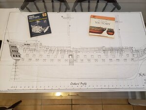
I fell in love with the aspect of one day being able to scratch build a cross section of the HMS Victory. I acquired the AOTS The 100-gun ship Victory by John Mckay and HMS Victory Owners' Workshop Manual by Peter Goodwin. Both books have extensive details and I must point out that Mr. Goodwin's book has a lot more historical information and plenty of colored photos from different areas aboard the HMS Victory for reference. There is plenty of information within both books for a person to feel comfortable enough to take on this challenge. The challenging part for me was to decide how large of a cross section I wanted to build. I previously constructed a cross section of the HMS Triton but did not add enough frames to incorporate the full main channel, thus not having enough space to add all of the ratlines. With this in mind, I decided to go ahead and order plans from Mr. Mckay.

After doing research and finally getting an email address, I was able to get in contact with Mr. Mckay back in January 2019. Mr. Mckay was an absolute delight to work with and after discussing which sheets of his drawings I wanted at 1:48 scale, we exchanged information so as to send him his funds via Paypal. Once the funds cleared, Mr. Mckay sent me my drawings and I could not have been more pleased with them. If Mr. Mckay is any sign of Canadian hospitality and professionalism, then I must say that Mr. Mckay is an ambassador for our neighbors to the North. So Mr. Mckay, if you ever read this post, many thanks for your hospitality and professionalism.

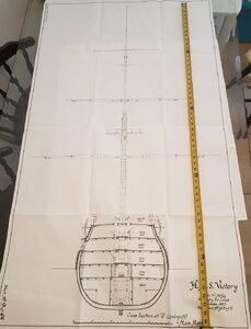
Now that I have the drawings on hand, I am able to decide how large of a cross section I want to tackle. Since I want to add all of the main mast's ratlines, I have decided to start from frame (B) going aft to frame 17 in order to have the full main channel on my cross section. I also want to add the main mast all the way up to the main pole mast. Once completed, the cross section will be massive. She will be 55 1/2 inches (140.97 cm) tall from sole plate to main pole mast and 31 inches (78.74 cm) wide from either side of the main lower studding sail booms.

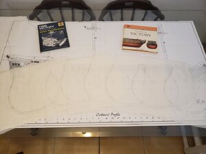
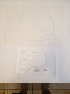
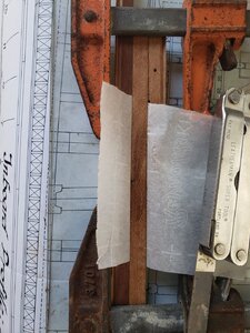
Since I decided to go from frames (B) to frame 17, I placed tracing paper of the drawings and finally have patterns to work with. I chose this method because I did not want to ruin the original drawings so as to keep them pristine as long as possible. After completing the drawings, I could not resist and wanted to compare one of my drawings to one of the drawings of guild's group project, the Blanford. Talk about one huge difference. The Blandford, at frame 1, is a modest 7 inches (17.78 cm) wide while the Victory, at frame (B) is a whopping 12 1/2 inches (31.75 cm) wide.

Below are a few photos of what I have thus far. Please enjoy and I look forward to updating everyone with my progress.

Raymond

20200508_082954.jpg20200508_083053.jpg20200508_083427.jpgVictory's height.jpg
 
Greetings Everyone,
I would like to start off by thanking everyone who has welcomed me back. Yes, I know it has been a while since I posted anything, and quite frankly, I felt a little bit uncomfortable commenting on and/or asking questions on other peoples work. Now that I am able to share my work, we can actually go tit for tat on each others progress. That being said, let me talk about how I started my project.

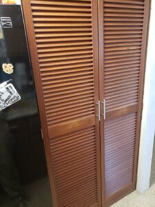
About two months ago, I acquired six 40 to 50 year old mahogany closet shutters. I was able to salvage two of the six doors and used them on the Admiral's kitchen pantry. Did I suck up to the Admiral? You bet your butt I did. Aftercall, how else can I get away from the honey-do list and be able to get a chance to work on my dream.

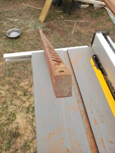
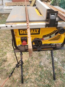
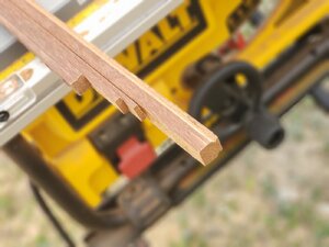
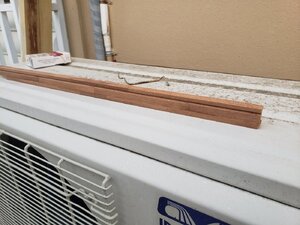
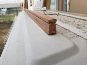
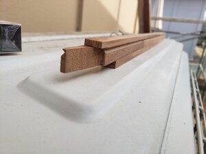
The left over shutters were then taken apart and stored in my work shop. I used one of the shutter's stiles and ripped it on my table saw at 7/16" (12 mm). Once I had the correct thickness, I placed the blade on my table saw at a 45 degree angle and lowered it so that the blade projected far enough to cut the rabbet on both sides. Once the rabbet was complete, I measured the height for my keel and ripped the board from the stile followed by the false keel, sole plate, and finally the rising wood since all of these timbers are of the same width.

Now that I had my timber on hand, I proceeded to work on the keel by cutting each section to length according to my plans. Since I am working on a cross section, all I need is a total of four out of the seven sections necessary for a full build. I then cut a pattern for the scarf joint and transferred the design on each section of the keel. I must point out that the length of the keel so far is longer then will be used. The reason for the extra length is that it will be used to secure my work to a base so that everything can line up better the further along I go on my build.

Once the pattern was transferred to my keel sections, I cut each section individually and made certain that one edge of the keel married perfectly to the following section. Once I was satisfied that the sections paired up, I numbered them on the bottom so that when it came time for glue, each section met with its mate. After completing this section, it was time to tackle the sole plate and false keel. This was really easy, I just had to cut my designated timber at 4 inch (10.16 cm) sections and glue them to the bottom of my keel. Now there was a little bit of a hiccup when it came time to tackle the rising wood. While the plans are quite extensive, it does not show the length of the rising wood sections so I decided to average the length of the keel and cut my rising wood sections at 6 1/2 inch (16.51 cm) lengths which were then glued on top of the keel. All 17 sections where then glued up and clamped in placed until the glue dried. Once dry, I sanded everything down while addressing areas that weren't as snug as I would have liked. Now that everything was as I liked, I was left with an assembly of keel section that is 7/16 inch (12.5 mm) wide, 7/8 inch (24 mm) high, and 20 inches (50.8 cm) long.

The following photos will show you what I have thus far.20200508_120558.jpg20200508_120626.jpg20200508_120745_resized_1.jpg20200508_120859_resized_1.jpg20200508_121012_resized.jpg20200508_122122_resized.jpg20200508_122317_resized.jpg20200508_130754_resized.jpg20200508_130804_resized.jpg20200508_162525_resized.jpg20200508_162536_resized.jpg20200508_162550_resized.jpg
 
Last edited:
Greetings,
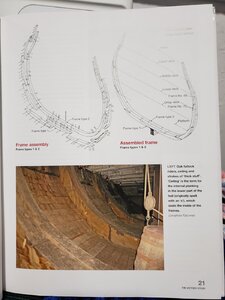
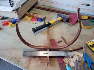
Since I have completed the keel, (with the exception of the bolts via the keel's scarf joints) I decided to start on the actual frames. I started out with frame (B) and cut timber to the desired thickness. I did notice on the actual plans I got from Mr. Mckay, that the upper sections of all frames started to get thinner and thought that it would also be a great idea to incorporate it on my build.

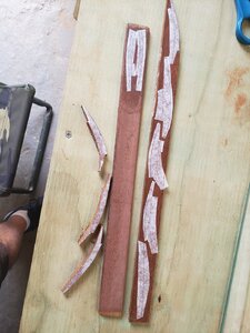
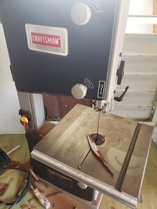
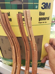
Since I have to use timber of various thicknesses, I have to ensure that I place certain patterns aside in order to use them on their corresponding timbers so as not to confuse myself. Once I had all the timber ready, I cut the copy of the frame assembly (B) and glued them to the correct boards. Once the glue dried, I proceeded to cut each section of the frame on my bandsaw and placed them to the side. While the bandsaw does save a lot of time, it tends to leave cut shavings on the lower edge that needs to be sanded smooth before I can dry fit them together with plastic clothes pins.

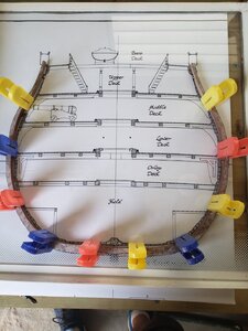
There were minor adjustments that needed to be addressed on all joints but was easily fixed with sand paper and/or sanding sticks. Once I was happy with the proper joints, I turned my attention to removal of the glued on patterns. When the patterns were finally removed, I placed a piece of glass over the original drawing and commenced gluing the frame sections together making certain that they followed the contour of the frame.

After the glue was dry, I removed the clothes pins from the frame and gently removed the frame from the glass. At this moment I realized that not all joints were as perfect as I would have liked. What I did to correct this was to add a little glue on any gaps that I saw, scrape the excess off, and finally sand the area with a section of fine sandpaper while it was still wet. This caused the fine dust to settle into the gap resulting in a much tighter looking seam between sections.

Once I was content with the first half of frame (B), I concentrated on working on the second half. The majority of Mr. Mckay's drawings show the middle of each double frames looking aft. There are a few references within his book that show how double frames overlap each sections joints but it left me wanting more. This is when I turned to Mr. Goodwin's book and found the information I was looking for in regards to the overlapping joints. Now that I had a nice warm and fuzzy, I started work on the second half of the frame.

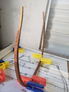
To make it easier to draw the second frame, I placed the first half on top of a sheet of paper and used it as a stencil. Once I had the overall shape of the frame, I placed tick marks on the sheet of paper where all the joints to the first half were so as to ensure I would not draw scarf joints in the same area on the second half of the frame. That complete, I then concentrated on marking new areas on one half of the drawing. Once I was content with the overall appearance, I folded the drawing in half and mirrored the other side. It was a matter of repeating the same process as for the first half with the difference that now I could actually glue them on top of the first frame. Once the glue dried, I addressed any gaps. Honestly, I am pretty pleased with how she came out.

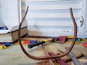
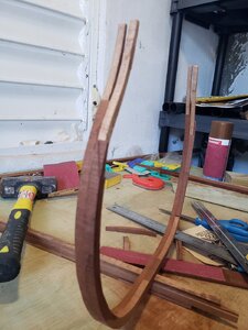
I will work on the other frames and post them once I have finished all of them seeing as it doesn't make much sense to keep repeating the information above for each frame. The following photos will show you the process I took and how frame (B) looks so far with the thinner boards on top.

Raymond

20200509_123145_resized.jpg20200509_123203_resized.jpg20200509_132035_resized.jpg20200509_151459_resized.jpg20200510_200151.jpg20200510_180356_resized.jpg20200510_180407_resized.jpg20200510_180441_resized.jpg
 
Great project Raymond and you are off to a good start.I hope you do not mind constructive criticism.I am not an expert on English construction of this period,but should the uppermost futtocks not touch each other back to back?The steps would then appear on the outsides of the sistered frame assembly

Kind Regards

Nigel
 
Hello Nigel,
I love the way your mind works brother. One would think that it would make sense to butt the uppermost futtocks. Upon looking at the plans I got from Mr. Mckay, all of the full frames were drawn with the thinner upper futtocks on the outer edge.

My educated guess would be that during that timeframe they had to ensure the higher the ship was the lighter it had to be hence thinning as you went up. I would also take a stab in the dark that the reason they placed the thinner futtocks on the outside edges was to maintain uniform gaps between frames. Had the the futtocks been sistered, a larger gap would exist between frames.

Like you, I am no expert but I hope and pray that Uwe would be able to shed some light on the subject.

Raymond
 
Hello Everyone,
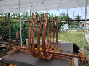
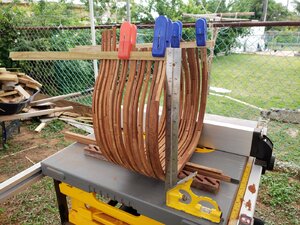
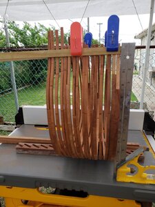
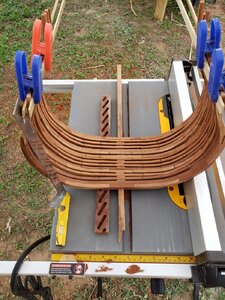
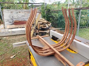
I am currently working on the frames and while the details are a tad time consuming, I believe it is worth the effort. Below are a few photos of my progress thus far. They are simply placed on the keel where they are roughly in the position that they will eventually go. I am in the process of waiting for a micro drill set that will be used for the bolts that hold the futtocks together. I will also drill the 8 bolts that hold the keel along its scarf joints.

On the last photo, you will see where I've marked the locations for the deck beam shelves. I will make these marks every 2nd or 3rd full frame. In between the full frames I will add the half frames. The actual plans show that the gaps between the frames will be roughly 1/8 inch (3.175 mm). I believe that I will take the liberty to adjust the half frames dimensions and make them slightly thinner in order to have a larger gap between frames to fully appreciate the construction process.

Raymond
20200513_141125_resized.jpg20200513_141145_resized.jpg20200513_141247_resized.jpg
 
Hi Raymond,
Here's another one to add to my long list of logs to watch!
What length will it be on the keel?
The section I'm building (not Victory) is from frame (B) to frame 13 but yours is to frame 17, so that's going to be BIG!
As you're dong a scratch build you may want to be including some details that aren't in kit builds? If so you may be intending to include the pump tubes down into the limber channels. If I may point out something before you get near creating pump components that I've just discovered that I now wish I had done earlier. (Please excuse me if you have a whole lot of experience in having done this before -- your experience will definitely be much more than mine!)
I 'floored' the entire hold (the ceiling boards, thick stuff, limber strakes and boards) then set about cutting through the limber boards and strakes for the sumps of the chain pumps' tubes.
That was a "small" task that took me the best part of 2 hours -- I used drills, mini saw, files and sandpaper -- and also had to carry out a repair on two of the boards and glue them back in place.
If I had made allowance for that before fitting the limber strakes and boards I would have saved myself that frustration!
. . . and I've still got to cut out for the elm tree pump tubes . . .
 
Last edited:
Hello Jim,
I am glad that you will be following along. I am certain that there are far more experienced modelers then myself but believe that I can hold my own. Lets just say that they are like Olympic swimmers, while I can doggy paddle my butt off.

I too will follow along your cross section build of the Leopard. I especially like the tools you have devised for the purpose of ensuring your frames are correctly placed. I believe that while framing jigs are helpful, they are a waste of money. I am sure people will get upset with this comment but please allow me to defend myself. Framing jigs are valuable tools that will eventually be used once (unless of course people want to mass produce a particular ship). The tools you've built are great because I see that they can be used multiple times on various ships hence, time and money well spent.

As to the length of the keel from frames (B) going aft to 17, there is a length of approximately 13 1/2 inches (34.29 cm), the height of frame 17 will be 13 1/4 inches (33.65 cm), and the widest point will be 13 inches (33.02 cm). Mind you that this is the ship's dimensions sans mast which will give it an addition height of approximately 42 1/4 inches (107.31 cm).

I appreciate the heads up in regards to tackling the areas where the elm tree pump (goes through full frame for sea water suction) and the bilge pumps (where accumulated water gets pumped overboard). I will also cut out the limber gates (cut-out notches on all lower frames near keel allowing water flow towards bilge pumps) from all frames.

I must run back to my work shop. The grand kids are driving me crazy and I need the sanctuary of my work shop to keep my sanity.

Raymond
 
Greetings,
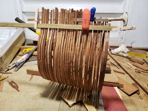
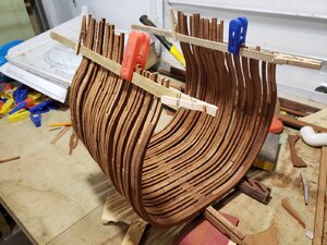
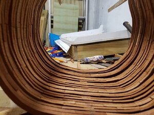
This is just a quick update to my build of the HMS Victory. I am gradually working my way aft from frame (B) and am currently on the first half frame after full frame 5. So far, I have a total of 5 full frames and 7 half frames completed. I need an additional 6 full frames and 11 half frames to get to where I want to be which is frame 17. It s quite possible that I may add an extra half frame behind frame 17 as a means of incorporating a full deck beam so as not to worry about where the deck ledges and carlings land.

Below are just three photos showing how she is starting to get that rough shape.

Raymond20200516_170623_resized.jpg20200516_170630_resized.jpg20200516_170641_resized.jpg
 
Hello Everyone,
A minor update to my build. I have completed frames up to frame 11. I still need three more.sets of frames consisting of 13, 15, and 17 not to mention the six half frames that fill the gaps between them. Below are photos to show you how she is coming along.

Raymond 20200521_195905.jpg20200521_195912.jpg20200521_195920.jpg
 
Greetings,
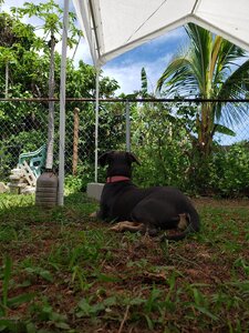
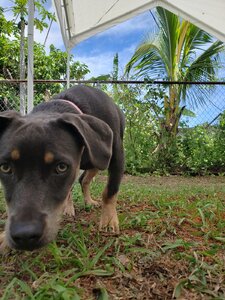
Not everything we do in life revolves around ship building. Sometimes we have to take everything in around us and just admire life in general.

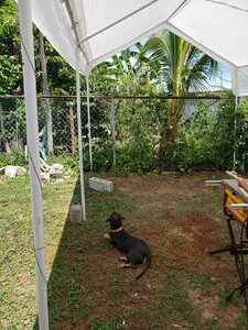
My dog Blu loves to be around me and whenever I go to my workshop she wants to come along. Let's just say that she entertains me with all that she does.

So, as I was getting ready to cut some timber, I noticed that Blu was extremely focused on something other then me. When I look towards her focus of interest, that's when I noticed the 2 foot long iguana walking on the chain link fence in the back yard.

I thought it would be the perfect chance to break the monotony and take a few photos. Needless to say that when I got down on my belly to take a photo from her point of view, that's when she decided that dad was a whole lot more interesting.

Raymond
20200522_112136.jpg20200522_112201.jpg20200522_112217.jpg
 
Back
Top