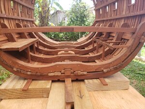
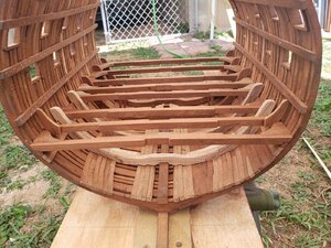
HMS Victory Cross Section, POF ,Scale 1:48 by Raymond Deliz

Greetings,

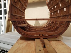
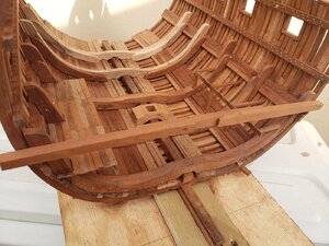
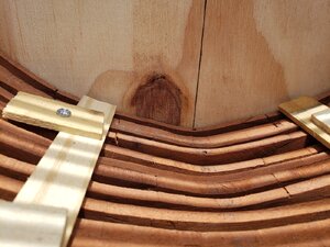
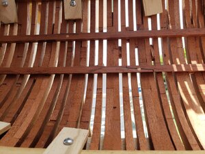
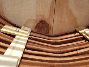
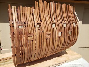
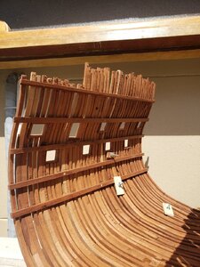
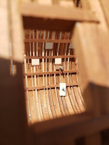
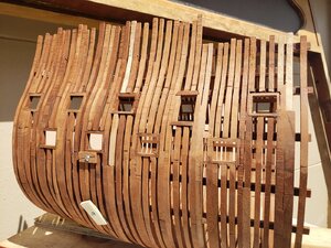
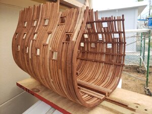
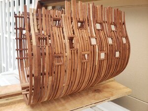
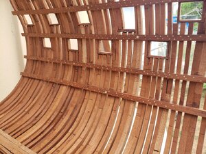
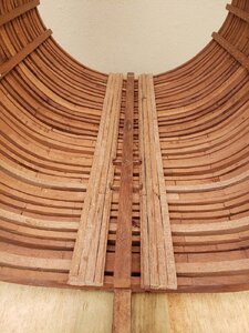
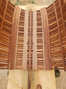
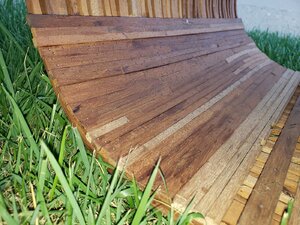
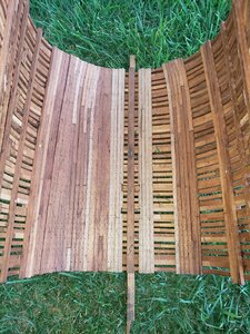
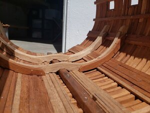
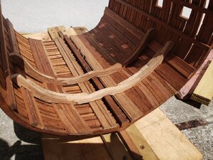
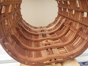
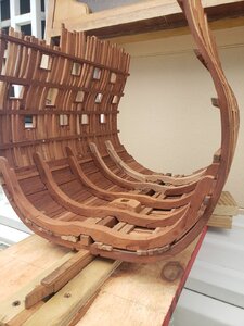
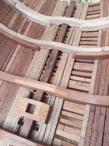
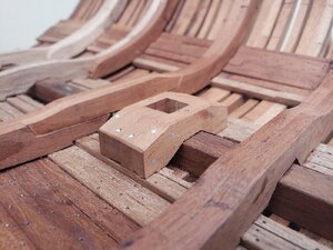
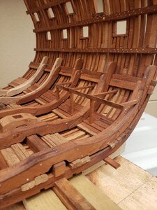
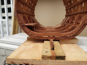
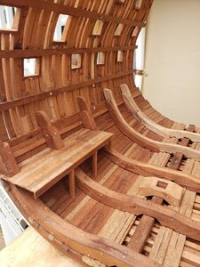
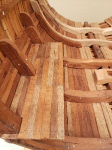
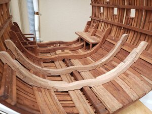
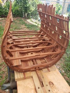
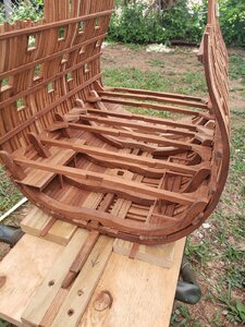
Today's work consists of adding all of the deck beams as a means of strengthening the hull. This aspect needs to be done in order fair the inside and outside of the Victory. There is a section in the aft frames, where the keelson will rest, that needs to be addressed prior to also adding the keelson.

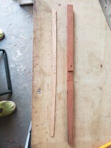
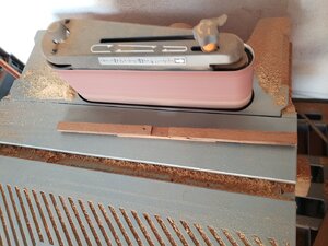
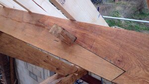
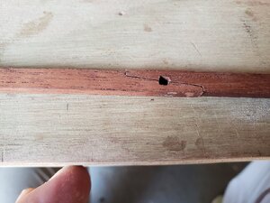
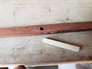
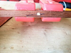
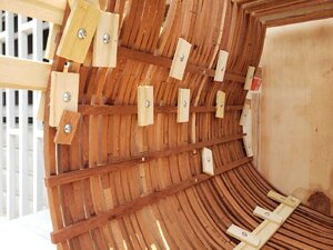
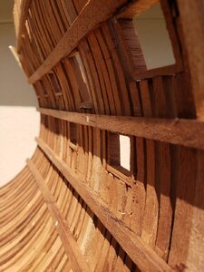
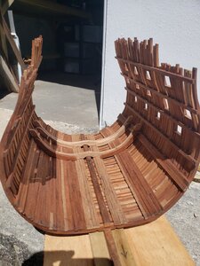
The process of the deck clamps is easy enough, however, the angles are acquired through trial and error. After getting the deck clamps made, I realized that they could not be used to cover the entire length of my cross section. Since the scaled measurement would be 57 feet (17.37 meters), I determined that they would have to go in in sections. I could not find information within McKay's nor Goodwin's books so decided that the best course of action would be to roughly add a scarf joint per deck beam clamp. I looked with Goodwin's book and noticed a detail that I rather fancied and decide to incorporate it into the clamps. I am referring to adding wedges to scarf joints as an additional detail for my build. This small detail may be lost within my build behind hanging or lodging knees but thought that the extra step might be worth it if in fact one of these sections peeps through all structural elements.

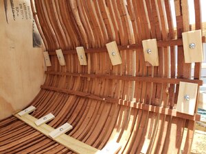
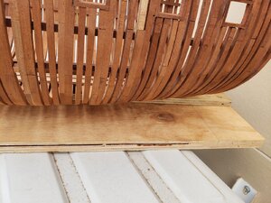
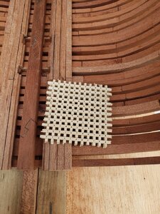
I currently have the four deck clamps on the starboard side and three on the port side. Since it is actually lunchtime I thought I would catch everyone up on my latest progress. In the last photo you will see the detail I need to address prior to adding the keelson.

Raymond20200530_131349.jpg20200530_131349.jpg45a05e0ddc1bac458bf1c58d6c138068.jpg20200529_120617.jpg20200529_121207.jpg20200529_121422_capture.jpg20200530_122033.jpg20200530_122043.jpg20200530_122054.jpg20200530_131349.jpg
 
Greetings,

Kurt:
I figured it would be a nice detail to add the wedges. Like you, I haven't seen in anyone's build before and thought, "Why not".

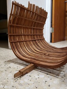
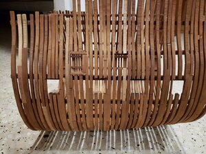
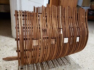
I hit a milestone today by being able to remove my build from the base. The deck clamps surely strengthened the frames and feels really solid. Care is still taken to ensure that I don't hit a royal SNAFU (Situation Normal, All Fudged Up). Please feel free to replace "Fudged" with whatever word you guys deem appropriate.

I also started marking out the entry ports and gun ports. While most people use patterns, I personally like taking measurements in order to avoid mistakes. Remember the old saying, "Measure twice, cut once".

Below are photos of what I have so far.

Raymond

20200531_193039.jpg20200531_193057.jpg20200531_193117.jpg20200531_193127.jpg
 
Hello everyone,

It's been a couple of days that I was not able to work on my Victory due to answering the call of the Admiral (like I had a choice). She wanted me to secure an outside storage area in prevention of this year's hurricane season.

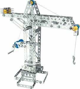
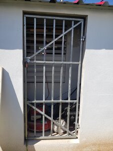
I am unsure if anyone else has ever played with an Erector Set as a child, but I thought that making a gate with square tubing would do the trick. I made a rough sketch of what I wanted, bought the materials, and proceeded to cut, drill, and bolt the gate together. I am pleased to announce that the mission was a success and now the Admiral is off my back until next week.

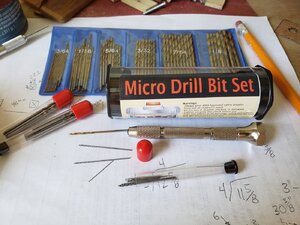
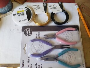
Yesterday, I finally received the micro drill set I ordered on the 8th of May. I was shocked to see (or barely see) the sizes of these small drill bits. Now that I had my drill bit set, i went to Walmart this morning and bought wire at 20 and 24 gauge plus a wirecutting kit. Now that I have everything in hand, I can go back and drill the deck clamps and add the bolts. Wish me well, I'm going in.

RaymondEitech-Classic-Series-Cranes-e1543405330292.jpg20200603_091612.jpg20200603_092432.jpg20200603_092555.jpg
 
Greetings Fellow Shipwrights,

I know it's been a few days since my last post but I came across a slight problem while working on the gunports. I was not really liking how the gunport sills were coming along so I decided to use a method I've seen on a previous post. If I am not mistaken, it may have been Zoly's post of the Ontario In which a long square wooden tube is made and then cut into slices for the gunports.

I decided that this would be my course of action and made the tube for the gunports. While awaiting for the glue to completely cure, I went ahead and started marking the areas where my gunports would be located. It was a matter of finally cutting the sections of frames that required gunports, cut a slice of wooden tubing, and gluing it into place. While it is not the correct method of ship building, I believe that the ends justify the means. Tomorrow i will begin on the upper deck and leave the quarter deck's gunports for a later date.

Below are a few photos of what I have so far. You will note that slight repairs were made on the portside's lower deck gunports. The repairs will not be seen once the planking gets underway.

Raymond 20200606_145911.jpg20200606_145927.jpg20200606_145940.jpg20200606_150013.jpg20200606_150029.jpg
 
Hello everybody,

Here is a small update on where my Victory stands today. Upon completing the gunports on the upper deck, I turned my attention to to faring the frames, both inside and out. Once I was satisfied, I decided to drill bolt holes on the portside deck clamps. I used toothpicks to represents the bolts but am not too sure if I like them. I have two options, I can use a fine point marker and darken the tooth picks or re-drill and use the black bristles from my broom.
You guys might be thinking, "Hey Ray, didn't you get a micro drill set for that purpose?". Yes I did but it seems either the drill bits are too small for the wire or too big. I cant quite get that happy medium as of yet.
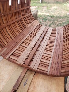
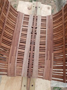
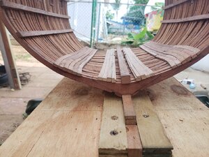
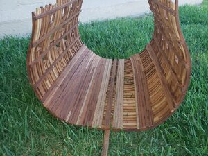
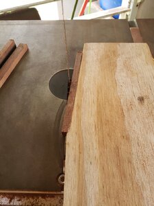
Also, while I was contemplating what to do about the deck clamps, I went ahead and added the keelson and the thick stuff closest to the keelson. I've also made a jig for the production of grates. All of the cross cuts are made with the jig on the table saw and then the timber is ripped on the band saw. If I am not mistaken, the gaps of the grate boards is 1/16 inch (approximately 1.5mm). The actual thickness of my table saw's blade is 3/32 inch (approximately 2mm). Since I want to construct every aspect of my Victory without having to buy anything, I have decided that this small difference in size is acceptable.
Below are a few photos of what I have so far.
Raymond 20200611_174435.jpg20200611_174411.jpg20200611_174405.jpg20200611_174421.jpg20200611_174358.jpg20200611_182147.jpg
 
Hello everyone,

I've continued to add the thick stuff material in the hold and so far it is looking good. That was the good news, now for the bad. I came to the conclusion that with the hand tools I have, I will not be able to manage adding treenails to my build the way others have. It is a process that I have not yet mastered that others have made it seem easy. What I will do however is stick to what I know best, simulated treenails. I use an awl to mark the locations of the treenails with a little simple and follow up with a pencil.
Some may not like this method but it works for me and quite honestly, I really like the way it looks. Below are a few photos and please do not judge me to harshly.
Raymond 20200613_162957.jpg20200613_163007.jpg20200613_163017.jpg20200613_163026.jpg
 
Hello everyone,

I have decided that I will fully plank half of the Victory while maintaining the other half with minimal planking. I decided that I will fully plank the starboard side due to the fact that I already have the plans for it showing the starboard side. In this way there will be no mistakes trying to mirror the planking for the port side.

I have already finished the thick stuff and ceiling up to the bottom of the orlop deck clamp. Tomorrow I will start working on the riders. The full ship has a total of eight riders but I will only have to worry about five of them for my cross section.

Below are a few photos of where my build is as of today.

Raymond

20200616_180243.jpg20200616_180303.jpg20200616_180318.jpg
 
Hello everyone,

The last time I posted, i happily informed you that i would start working on the Victory's riders. So far, i have two of the five needed for my cross section. It is a really simple thing to do, albeit a little time consuming. The easy part is cutting out patterns, transferring the design to the timber, and finally cutting it on the band saw. The part that gets a little tricky is when you have to follow the contours of the thick stuff and not having a contour gauge. What I do is simply place the rider's individual pieces and use a pencil and mark the location of the thick stuff. Little by little, I cut these marked areas until the piece fits comfortably in place. I know it is a little time consuming but it works for me.

Below are a few photos of the riders.

Raymond 20200619_101054.jpg20200619_101108.jpg20200619_101145.jpg
 
Great job, Raimond!! Those POF builds are really fascinating to watch! It is like building a real ship from the ground up. Many thanks for you build log. Everyday I learn something new. Now I know what are the riders... ;)
 
Hello everyone,

It's been a few days since the last post but I think it was well worth it. The first two sets of riders were easy but these last three really wanted to kick my butt. Man, talk about time consuming. Each section of the last three riders had to be fitted, filed, sanded, refitted, refiled, and finally resanded. Once they were done I danced a little "Victory Dance" (pun intended). I still have to go back and add my bolts but that will be fairly easy.

I also tackled the mast step which was completed in no time (if only the riders were that easy). Before completely securing the main mast step in place, I made sure that I added the bolts for fear that the riders would be in the way.
Here are a few photos showing you what I have done so far.

Raymond 20200624_140259.jpg20200624_140336.jpg20200624_140327.jpg20200624_140317.jpg
 
Hello, Raimond.

The time spent well worth it! looks good! Is there a reason you made the last rizers of different timber?
 
Hello, Raimond.

The time spent well worth it! looks good! Is there a reason you made the last rizers of different timber?
Hello Jim,

The timber I am using are from 40 or 50 year old mahogany doors. At first I thought it was all the same but now I see that some other type of lumber may have been used in the construction of it. What I will do is incorporate some more of that lighter lumber in different areas in order to balance out the look and feel of my build. Being born and raised in Brooklyn myself, it kind of reminds me of those old brick buildings that had lighter and darker bricks. If it comes to a point that it may not look how I imagine it, I will dye the lighter lumber to make it match the rest.

Raymond
 
Hi Raymond,

That's a really great job on the riders . . . and I understand when you say it was a bit of a butt-kicking job getting them to fit properly!

If I may say, your section is really "riding along" now!
 
Greetings everyone.

I have finished adding the bolts to all of the riders and am happy that it's done and over with. After completing the riders, I sat back and pondered what the next step would be. After reviewing my plans and drawing inspiration from someone else's build, I decided that I would next tackle the platforms in the hold. Mind you that since my cross section is quite long, I've realized that the lower hold has three platforms I must address. They consist of the port and starboard platforms on either side of the mast well and the rear platform just forward of the spirit room bulkhead. Since i will fully plank the starboard side all portions of platforms on the starboard side of the keelson will by planked. Everything on the port side will just be framework so as to appreciate the carpentry work involved in ship construction.

The spirit room platform can't be done until I start working on the orlop deck beams. The reason I must wait is that platform rest against the spirit room bulkhead and without having the deck beams in place I can't determine how high that bulkhead will be.

Since I am talking about the deck beams, I must point out that the mast well and shot locker are also on the back burner until completion of the deck beams.

Below are a few photos of what I have thus far.

Raymond

P.S. I get my inspiration from the attached website. It is here if anyone should feel the need to get ideas from someone else.

20200626_141407.jpg20200626_141412.jpg20200626_141419.jpg20200626_141426.jpg20200626_141449.jpg
 
Hello everyone,

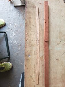
Just like I mentioned in Yesterday's post, I started working on the deck beams. The toughest part was determining the dimensions I would run with. If you look at Mr. McKay's drawings, you will notice that certain beams are constructed with three sections of timber due to the distance from port to starboard. While it seemed simple enough, I noticed that the middle section of the beam varied in length from beam to beam. Being retired from the military, I have not lost the sense of uniformity and decided that I would cut all the middle sections of the beams the same length. Having this concept in mind I drove in and started cutting timber.

After cutting all the timber for the orlop and lower deck beams, I came to the realization that I needed a jig in order to cut the scarfs in a uniform matter. After pondering how I would go about it, I made the jig ensuring that all the cuts would have the same angle and having the same distance. Once that was complete, I tried the cuts for the first beam and was happy with the results.

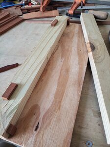
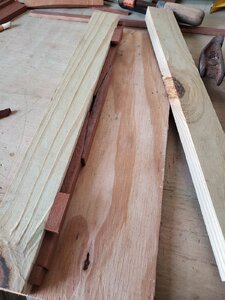
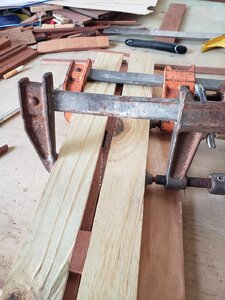
Now that I had the angle jig situated, I also realized that I would need another jig in order to glue the pieces together. What I did was cut some paneling material and pine boards and set it up in such a way that the outer extremities would butt up against a stop so that each of the sections would have a 1 inch gap (25 mm) between them and then it would be a matter of gluing the middle section to them. Once glued, I placed another pine board against it and clamp it in place applying pressure to the full beam. After a few minutes I would remove it, place it to the side and continue with the next beam.

Once I had all the beams for the orlop deck completed, it was a matter of finally adding the chamfer. This was fairly easy due to just taking the time and making a master pattern that will be used for all of the deck beams. After making the master pattern, I transferred the lines to the raw deck beam and used my table belt sander. While it does raise a lot of dust, it is a lot safer then trying to use the band saw and risking going to far to the line and ruining the beam.

Below are a few photos depicting what I have explained. In the event there are any questions please ask away.

Raymond 20200627_155358.jpg20200627_155640.jpg20200627_155754.jpg20200627_155846.jpg20200627_160500.jpg20200627_160512.jpg20200627_160559.jpg20200627_161324.jpg20200627_161331.jpg
 
Greetings fellow shipwrights,

Today I have completed the orlop deck beams which are temporarily pinned in place. The reason for skipping ahead to the beams was for the purpose of determining the height of the hold well and the spirit room bulkhead. Now that I have the property height, I can start taking measurements for said items.

Upon completion of bulkhead and hold well, I will see about incorporating ballast and cargo such as water barrels and timber that was used for firewood by the cooks. I am still waiting for my mini lathe to arrive from China. If in the event it does not arrive on time I will go to "Plan B" which will be using my drill as a makeshift lathe. I do not really want to go to the drill but if necessity calls for it, so be it.

Here are a few photos of how she looks today.

Raymond 20200629_125351.jpg20200629_125358.jpg20200629_125412.jpg20200629_125425.jpg
 
Back
Top