-

Win a Free Custom Engraved Brass Coin!!!
As a way to introduce our brass coins to the community, we will raffle off a free coin during the month of August. Follow link ABOVE for instructions for entering.
-

PRE-ORDER SHIPS IN SCALE TODAY!
The beloved Ships in Scale Magazine is back and charting a new course for 2026!
Discover new skills, new techniques, and new inspirations in every issue.
NOTE THAT OUR FIRST ISSUE WILL BE JAN/FEB 2026
You are using an out of date browser. It may not display this or other websites correctly.
You should upgrade or use an alternative browser.
You should upgrade or use an alternative browser.
Hohenzollernmodell 1660-1670 Scale 1/75 POF build by Stephan Kertész (Steef66)
- Thread starter Steef66
- Start date
- Watchers 57
-
- Tags
- 1:75 dutch two-decker pof
Wow...informative research on aspects I have never heard of. Succinctly presented. Thank you.Thanks again to everyone for the likes and visits to my log. Some time ago, I had promised to give another explanation about the "scheerstrook" Herewith, I hope it is understandable.
******************************************************
Misconceptions and beliefs about the “Scheerstrook”.
In my search for answers about various construction phases and parts that appear on a 17th-century ship, that of the “Scheerstrook” has been my biggest quest. All sorts of claims were made about the course and function of the “Scheerstrook”. Much of what I have discovered are mainly conclusions you can draw from the none you study and what you can see about it on paintings and drawings from that time and the written down part of Cornelis and Nicolaes.
Fortunately, I also received help in my search from people who you can assume know what they are talking about. That helped very much in being able to write down this piece. In the hope of helping others with it.
Mind you, it is as I see it now and therefore not a hard truth. Because this topic still shows many gaps that can be interpreted differently. And maybe after finding more evidence regarding the “Scheerstrook” in archaeology we will get a better explanation.
My findings in a nutshell:
What is the “Scheerstrook”?
In the "shell first construction method" and the slightly more modern "Frame first construction method", in both methods, construction began with laying out the keel and raising the bow and stern with wing transom, fashion pieces, transom and stern timber. The garboard strake was then applied along the keel. The further course determined which construction method came next. A rope was then stretched between the bow and stern (‘scheer’ line). A strong rope was used for this. Because to the rope, vertical ropes were placed between the ‘scheer’ line and the already placed floor timber, tightened and secured to the keel. This allowed one to see from the ‘scheer’ line the course of the sheer.
The “Scheerstrook” was a temporary planking course, which ran on both sides of the hull from the bow beam along the placed uprights to the stern beam of the stern and was fastened to these sections. In side view, the “Scheerstrook” indicated the intended course of the sheer and the intended course of the hull circumference there. The lowest point of the 'scheer' line was taken as the position where the lowest scupper hole of the orlop deck was to be located. The shearline runs parallel to the 'scheer' line.
All this was done because a 17th-century Dutch ship was not built from a technical drawing but determined by the master builders by eye. Of course, they made notes and sketches to see if they were in the right direction or to calculate curves. But a real construction drawing from which you could read measurements or determine shapes to scale. No, they didn't. The skill of the people at the shipyard was also of a high level. They knew what they were doing and everything was under the direction of the master at the yard. A conclusion already written down by Ab Hoving. And which, having studied it, I can fully endorse.
What is the “Scheerstrook” used for?
With the above explanation of what the “Scheerstrook” is and the underlying idea that no construction drawing was used, one can note that the main function of the “Scheerstrook” is that when a ship is built, it serves as a temporary tool to record the ship's construction shape.
Temporary, because once it had fulfilled its function, it was removed and even, in some cases, reused on the next similar ship. Pretty convenient since it amounted to quite a construction which I will come back to later.
So the “Scheerstrook” was, as it were, a construction template for the frames and frameparts that were still to be attached. But markings were also laid out for the parts on the ship. Think of: hatches, gun ports, masts, deck beams and the location of the deck amidships. The “Scheerstrook” runs along the lowest scupper of the orlopdeck. That was amidships. We know that the deck also became increasingly flat on these ships and no longer ran parallel to the sheer. That place where the deck at 1/3 of the ship's length (the 'hals') no longer followed the course of the “Scheerstrook” was also marked on the “Scheerstrook”. Also, the wales ran parallel to the “Scheerstrook”. So you can see that the “Scheerstrook” had many functions during construction and was very important. After all, construction was not done from drawings but by eye. And then it is important to be able to orientate during construction.
How and from what is the “Scheerstrook” made?
For that, we look at what Cornelis writes about the “Scheerstrook”:
View attachment 398233
“ ’t syn Planken, breed 8, 10 of 12 Duimen, en 2 a 3 duimen dik” translation: “ they are boards, width 8, 10 or 12 thumb, and 2 a 3 thumb thick”
Translated to metric this is 30.9 x 7.7 cm.
Cornelis mentions that the bend is burned at the bow. This makes it plausible that the beam is made of oak. After all, that is burned to bend. The fact that it is reused also hints that it had to be durable wood.
A large ship soon has a “Scheerstrook” with a length of 45 metres. without connectors and so forth, you're talking about at least a cubic metre of oak wood. And with an average density of oak of 750 kg/m³, you're talking about a weight of over 800 kg per side. It was hard and heavy work for the carpenters.
Nowhere have I found a clear description on what wood is used for the “Scheerstrook”. But conclude from the findings in the old books, the purpose and construction of the “Scheerstrook” that it must have been oak. One clue I got from Jaap Luiting who explained to me the burning of the bend at the bow. This could only be done with oak in that way he indicated. After a long search, I found out that this was traditionally only done with the harder woods, such as oak indeed, but elm, beech, etc. also qualified. In any case, not the softer woods. I myself also draw the conclusion from the fact of reuse to take solid strong wood. Also, the “Scheerstrook” was used to align the frame parts. These are no matchsticks either, but thick oak beams. Which require a solid support of a solid type of wood. I may then conclude from these findings that we are talking about oak. This is also what the vast majority of the ship consisted of. So this was also available in the yard.
Another science I discovered was that burning a heavy strakes or wale could take up to 20 hours at the Batavia yard.
Does the “Scheerstrook” run across the widest part of the ship?
For that, I would first like to describe the moulded depth of the ship and what part is meant by it.
In the 17th century, the moulded depth (Holte) was measured from the top of the rabbet of the keel to below the mainframe transom of the orlop deck, without counting the bend of this beam. Edit 6 okt 2023
View attachment 398602
At the moulded depth, therefore, the lower scupper hole is also located and you can therefore also say that the “Scheerstrook” at that point is the lowest.
Cornelis is writing:
De holte by de konft - kundigen genomen werd vande bovekanc van't Vlak, tot onder den Overloop aan Boord, ter plaatfe daar 't Schip alderlaagft is, en fijn eerfte Uitwateringe heeft. Sonder dat de Rondte van de O verloops-Balk daar by.moet werden gedaan.
But if you take the aforementioned theory of N.H. Kamer where he uses perspective projection Analysis to show in drawings that the widest point is not always on the moulded depth but can also be above and below it. Examples of this can be found at Cornelis's book.
It is and remains a somewhat questionable fact. The model of the Prince Willem from the 17th century also shows that the widest part is below the moulded depth. And thus the model actually says that the “Scheerstrook” does not run across the widest part. But from the other side, it sounds illogical because the “Scheerstrook” is used to determine the construction of the ship. And if it runs across the widest part, does sounds more plausible.
I second the statement that the “Scheerstrook” does not have to run across the widest part. It does happen very often that it does. But there are exceptions. The model of the Prince Willem also shows this. Both the museum model and the one at my house.
View attachment 398234
View attachment 398236
Another conclusion I grant to this is the way these ships were built. Not from drawings and with the materials available. For the bilges, expensive pieces of wood that had grown into the right shape were used. That made the bilge very strong, but it also limited your design. This had to be adapted to the wood in question. As a result, it could therefore happen that a ship got a slightly different shape than what was envisaged and, as a result, the wider part did not always get the moulded depth. After all, we should not forget that carpenters were craftsmen who built a ship with the material available and wasted as little wood as possible to keep costs down. Speed of construction also factored into this story. They were not going to waste time handling a rule that was not necessarily necessary to apply. If you look at ship proportions in Cornelis and in Nicolaes' books, they deviated from the proposition length-width ratio more often than they complied with it. I personally think it had to do with the material available.
Does the lower wale run flush with the “Scheerstrook”?
Short answer. No! There are plenty of examples that this is not so. On Witse's Pinas, for example, it runs between both lower wales. And so there are plenty of examples where this is clearly not the case. The aforementioned Prince Willem is another example. What is, however, is that the wales run parallel to the “Scheerstrook”. The “Scheerstrook” was temporary and after it had fulfilled the function for which it was needed, it was removed and sometimes even reused for the next similar ship.
Is a “Scheerstrook” necessary to build a model?
Do you build a model according to drawing or existing example. Then the answer is no. This will be too complicated to achieve. Nicolaes gives all kinds of values to make the “Scheerstrook” and to scale this is difficult to recreate. Also, you have drawings and from these you can follow other construction lines to build your model. You see this in a POF build that people make a mould to about half height to be able to fix the frames in there. Here is a photo I took of Christiaan's build where this can be seen. But also in my build I have waterlines available from a drawing and I would be foolish not to use them. After all, I am building an existing model from which drawings have been made.
View attachment 398235
Only when you aim to build a model you only have the measurements of then you will have to and follow the whole process to build. In my case, a “Scheerstrook” is not necessary. It doesn't have to be by eye. As I mentioned earlier that this was the purpose of the “Scheerstrook”, to build by eye.
Good morning Stephan. It is good to hear you have both hands mostly active again> I love your work and looking great. For e.eg. the way your treenails came out is my kind of modelling- Im not into these perfect nailing (looks pretty but not real). Cheers GrantHi Folks, Welcome back!
September last year I worked on this ship the last time. After that I did a lot of research on this one, worked on the Clipper and the Prins Willem. And read a lot in the time my hands where offline. But now I can work again with my hands. Have to avoid to much power on my left hand but I can work with wood again.
So I started making"and placing those "buikstukken". But I also did a Re-do on the stern.
View attachment 441663
These hull planks are placed vertical, did this without thinking. I was to much with my brain somewhere else I think. Maarten suggested once that these are wrong. I should replace them in that time, because I knew it will be a thing I will never forget. That little voice always telling me "they are wrong".
It was a very difficult job to get them of and a more difficult job to get them back, because the hull planks on the bottom are already installed and it was difficult to get them fit in. But I succeeded. The pictures show the planks installed, the glue isn't fully dried and I need to sand it. (the gun ports need to cut out too)
View attachment 441664View attachment 441665View attachment 441666View attachment 441667
The more I work on this model, the more I realise the scale of it is to small for this kind of build. 1:50 was a better scale to work in. So maybe a major Re-do is coming up.
- Joined
- Aug 8, 2019
- Messages
- 5,569
- Points
- 738

Thanks Paul, I'm satisfied tooA nice recovery on the stern sheathing Stephan!
Thanks Maarten, yes I'm happy to. Love to work with rope, but wood is more fun to do. You can get lost in it and relax.Hi Stephan,
Welcome back, allthough you never left
Happy to see you back on Hohenzollern and good repair on the tuck.
- Joined
- Aug 8, 2019
- Messages
- 5,569
- Points
- 738

Thanks Johann, a compliment of a specialist like you is appreciate.Very nice progress !
hi Grant, thanks for the compliment. It was a lot of work, reading and study.Wow...informative research on aspects I have never heard of. Succinctly presented. Thank you.
Good morning Stephan. It is good to hear you have both hands mostly active again> I love your work and looking great. For e.eg. the way your treenails came out is my kind of modelling- Im not into these perfect nailing (looks pretty but not real). Cheers Grant
Thanks for your concern about my hands, yes I can work again with them. Need to take an extra break and can't work many hours at once, but at least I can work with them.
The treenails I could make it perfect for sure, but like you, I like it more in this way, looks more real.
- Joined
- Oct 23, 2018
- Messages
- 886
- Points
- 403

Hi Stephan,
it is good to read that you are building again on your Hohenzollernmodell. I missed your log in the last few months.
I have a question to your wing transom. I am surprised that you have carved the decoration on it and that the planking end under the beam. By English ships the planking ends on the wing transom and wider decorated "plank" saves the ends of the normal planks. Are you sure that your method is right or is it a small smplification?
- Joined
- Aug 8, 2019
- Messages
- 5,569
- Points
- 738

Thanks Christian, I don't know exactly how it is done on English ships. And maybe that's better during my build. I only study Dutch ships. On my research the planks end against the wing transom.Hi Stephan,
it is good to read that you are building again on your Hohenzollernmodell. I missed your log in the last few months.
I have a question to your wing transom. I am surprised that you have carved the decoration on it and that the planking end under the beam. By English ships the planking ends on the wing transom and wider decorated "plank" saves the ends of the normal planks. Are you sure that your method is right or is it a small smplification?
The HZ model:

The Vasa:
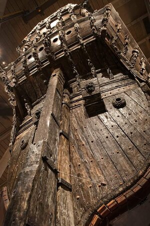
And the drawings of Ab Hoving:
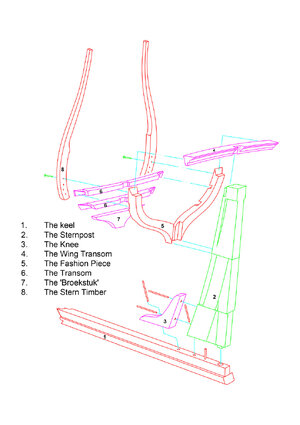
Hope this will answer your question.
Good to see you back to building. And very good to hear your hands are getting better!Thanks Christian, I don't know exactly how it is done on English ships. And maybe that's better during my build. I only study Dutch ships. On my research the planks end against the wing transom.
The HZ model:
View attachment 442169
The Vasa:
View attachment 442170
And the drawings of Ab Hoving:
View attachment 442171
Hope this will answer your question.
- Joined
- Aug 8, 2019
- Messages
- 5,569
- Points
- 738

Thanks Tom.Good to see you back to building. And very good to hear your hands are getting better!
- Joined
- Aug 8, 2019
- Messages
- 5,569
- Points
- 738

Thanks all for the visit and likes.
Making floor timbers is boring, and in this case a lot of work.
Between the drying of the glue a make other parts like the gun ports on the backside.
On the inside there are nails on the door, I make them by drilling a tiny hole and fill that hole with polymer clay. After heating shortly with a torch they come a little out of the wood and look like nails. The extra is the blackening of the wood on the inside. I like that to.
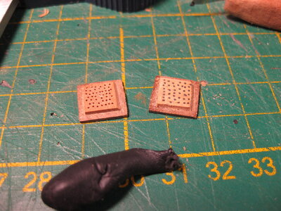
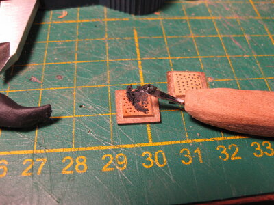
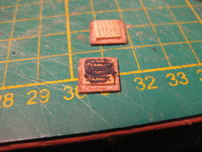
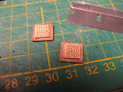
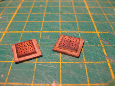
Then I came to the idea to make a lionhead on the inside.
My first attempt in castello, btw I used end mills. Sphere end end mill and a straight one with a little tapering in it. resp. 0,4 mm. and 0,6 mm.
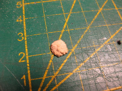
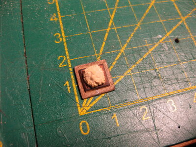
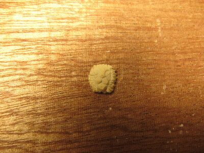
It's a first attempt, need to get the feeling and anatomy of the head. The next one will be better and smaller.
Making floor timbers is boring, and in this case a lot of work.
Between the drying of the glue a make other parts like the gun ports on the backside.
On the inside there are nails on the door, I make them by drilling a tiny hole and fill that hole with polymer clay. After heating shortly with a torch they come a little out of the wood and look like nails. The extra is the blackening of the wood on the inside. I like that to.


Then I came to the idea to make a lionhead on the inside.
My first attempt in castello, btw I used end mills. Sphere end end mill and a straight one with a little tapering in it. resp. 0,4 mm. and 0,6 mm.


It's a first attempt, need to get the feeling and anatomy of the head. The next one will be better and smaller.
Hi Stephan. On this scale it must be extra hard to make a convincing lion's head. The first attempt made me smile as I thought it resembled the old man Waldorf of the Muppets Show, but the second already has the anatomy of a lion's head. I am sure you get the hang of it and will produce ferocious lion's heads.
- Joined
- Aug 8, 2019
- Messages
- 5,569
- Points
- 738

Hi Stephan. On this scale it must be extra hard to make a convincing lion's head. The first attempt made me smile as I thought it resembled the old man Waldorf of the Muppets Show, but the second already has the anatomy of a lion's head. I am sure you get the hang of it and will produce ferocious lion's heads.
 Yeah those two on the balcony, actually there are planned two on the back, that's pretty much the same.
I made a new one and hell is this little bugger small. Almost impossible to do, just on wrong hit and the shape changes. I use nom the smallest end mill I got (0,3 mm. round) and it is till now impossible to do it right
The second attempt and still to big for on the gun door.
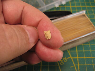
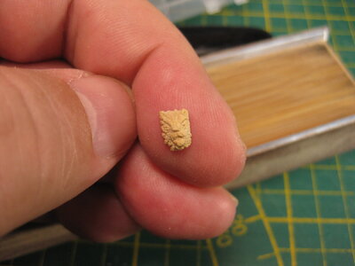
Or I still practise on and get it or I stop and forget it. Because I realise that there are more gun ports on the ship then only those two on the back....
Maybe someone got a nice picture of these lions that I can use to get the shape in my head. And give it another try.
- Joined
- Aug 8, 2019
- Messages
- 5,569
- Points
- 738

Thanks Paul, they give me a good feeling about my result, I thing I could achieve this. Less detail will do it.From my Vasa kit...
View attachment 442558
In fact I bet you could buy these from Artesania Latina???
- Joined
- Aug 8, 2019
- Messages
- 5,569
- Points
- 738

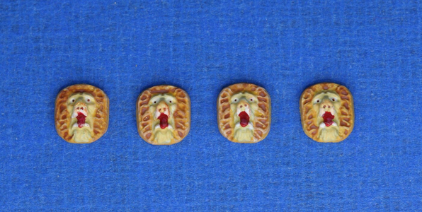
Time ago, I got a lot of modelling parts. And I had a box with all kinds of small ornaments. That's where I found these 4 lion heads.
 If anyone knows which kit they are from
These are quite suitable. See if I can recreate them or get them from somewhere. These are also not very detailed.
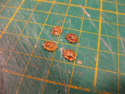
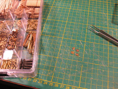
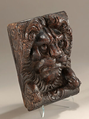
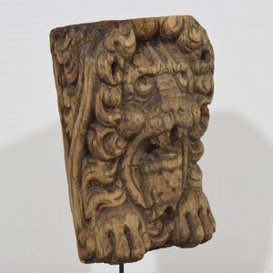
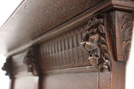
Then there are original lions I found on the internet.
16th century Dutch:
17th century Dutch:
A shelf with hooks Unknown age and country:
17th or 18th century Unknown country:
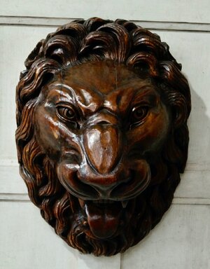
It is remarkable that the Dutch show the front paws of the lion in the figures. You don't see that on the Vasa or in other nations. At least I have not encountered it.
The first one, the 16th century Dutch, is when looking at it doable for me. At least I wil give it a try.
 If anyone knows which kit they are from
These are quite suitable. See if I can recreate them or get them from somewhere. These are also not very detailed.


Then there are original lions I found on the internet.
16th century Dutch:

17th century Dutch:

A shelf with hooks Unknown age and country:

17th or 18th century Unknown country:

It is remarkable that the Dutch show the front paws of the lion in the figures. You don't see that on the Vasa or in other nations. At least I have not encountered it.
The first one, the 16th century Dutch, is when looking at it doable for me. At least I wil give it a try.
- Joined
- Aug 8, 2019
- Messages
- 5,569
- Points
- 738

On the Dutch Forum I got a lot of reactions of the lion head of metal. Corel and Amati sell them


I can see a lion now Stephan…..next one will be roaringYeah those two on the balcony, actually there are planned two on the back, that's pretty much the same.
I made a new one and hell is this little bugger small. Almost impossible to do, just on wrong hit and the shape changes. I use nom the smallest end mill I got (0,3 mm. round) and it is till now impossible to do it right
The second attempt and still to big for on the gun door.
View attachment 442511View attachment 442512
Or I still practise on and get it or I stop and forget it. Because I realise that there are more gun ports on the ship then only those two on the back....
Maybe someone got a nice picture of these lions that I can use to get the shape in my head. And give it another try.

With all that lipstick on Paul, these guys are off to a trans partyFrom my Vasa kit...
View attachment 442558
In fact I bet you could buy these from Artesania Latina???
 .
.- Joined
- Aug 8, 2019
- Messages
- 5,569
- Points
- 738

@All thanks for the likes and comments (jokes to, I love them  )
)
These are the first working gun ports I ever made in this way. It was a sort of test on how to. Seen a lot of ways of how others made them.
I decided not to make the lion heads out of boxwood but order them at Amati. These are made in casting with a gold layer. I leave them in that way, I don't like trans lions. Not my thing
I need to blacken the iron part and sand a little everywhere, but in dry fit it looks good. And it works.
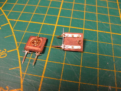
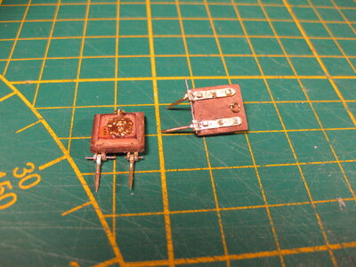
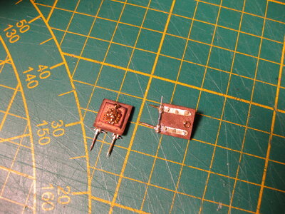
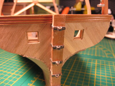
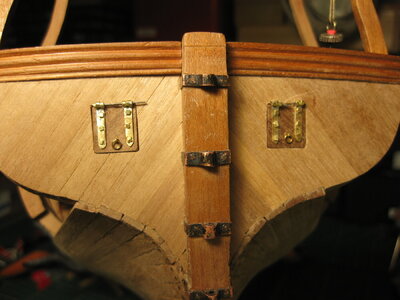
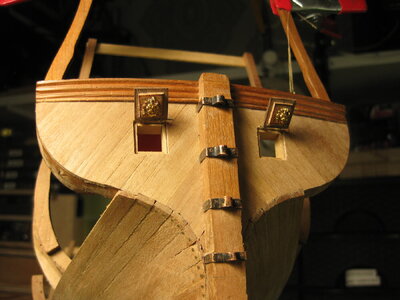
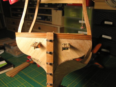
for these small hinges I use a brass tube of 1,5 mm, prass strip of 0,8 mm. thick and a brass nail. A steel rod of 0,4 mm is the pin (which are oversized till I finally fixed them.)
The square nails are ordinary brass nails I sanded the top square.
Next time I make a how to tutorial.
 )
)These are the first working gun ports I ever made in this way. It was a sort of test on how to. Seen a lot of ways of how others made them.
I decided not to make the lion heads out of boxwood but order them at Amati. These are made in casting with a gold layer. I leave them in that way, I don't like trans lions. Not my thing
I need to blacken the iron part and sand a little everywhere, but in dry fit it looks good. And it works.


for these small hinges I use a brass tube of 1,5 mm, prass strip of 0,8 mm. thick and a brass nail. A steel rod of 0,4 mm is the pin (which are oversized till I finally fixed them.)
The square nails are ordinary brass nails I sanded the top square.
Next time I make a how to tutorial.
Baai mooi Stephan.@All thanks for the likes and comments (jokes to, I love them)
These are the first working gun ports I ever made in this way. It was a sort of test on how to. Seen a lot of ways of how others made them.
I decided not to make the lion heads out of boxwood but order them at Amati. These are made in casting with a gold layer. I leave them in that way, I don't like trans lions. Not my thing
I need to blacken the iron part and sand a little everywhere, but in dry fit it looks good. And it works.
View attachment 443055View attachment 443056View attachment 443057View attachment 443058View attachment 443059View attachment 443060View attachment 443061
for these small hinges I use a brass tube of 1,5 mm, prass strip of 0,8 mm. thick and a brass nail. A steel rod of 0,4 mm is the pin (which are oversized till I finally fixed them.)
The square nails are ordinary brass nails I sanded the top square.
Next time I make a how to tutorial.


