Kingfisher 1770 1:48 POF

Paul! Lovely work. ROI is a great question. But if you are seriously asking whether your output is worth the time spent to make it . . . . You, and I think the rest of us, are only really asking the question: can I do this? Your work proves that the ROI on that question is enormous not only for your output, but for the inspiration of your shipmates. Thank you!

Blessings.
Chuck
 
Last edited:
DANIEL! After four years of watching me work did you really just ask if I made something the wrong size??? Have you not seen that I am an exacting perfectionist who is willing to go the extra mile to get everything just right!!!

Really!?!? :mad:

Actually, the one on the left is too narrow ROTFROTFROTF. I hate that you noticed ROTFROTFROTF.
Hi Paul, no comments on the work, just love it.
PS the gun port on the left is most probably the only one opening when the ship is in the water. The wood will swell and the gunport lids will be stuck due to your fantastic fitment ROTF
 
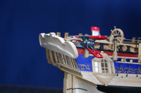
A quick update... I fabricated my first (ever) working hinges on the Kingfisher gun port lids. At 1:48 they were doable, though I feel like mine are a bit large and thus out of scale. I might have been able to make them smaller, but I already (embarrassed Redface) spent more than a day on these two hinges (along with a nonfunctional set for the vertical forward lid).

I'm glad I gave them a try... though I'm not sure the ROI worked out in my favor.

View attachment 503973

View attachment 503974

View attachment 503979

View attachment 503977

View attachment 503976

View attachment 503978

View attachment 503975

That's enough metalwork for a while...
Dangerous question, given the length of your blog, but could you give a little more insight on how you made these hinges?
 
Dangerous question, given the length of your blog, but could you give a little more insight on how you made these hinges?
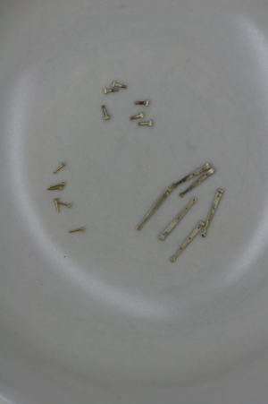
I soldered a brass tube onto a brass strip to make the strap; then I soldered a brass tube onto a brass rod to make the part that inserts into the hull. Finally, I took
a small brass nail - cut it off - and used it as the pin:


1741023638733.png

Next time: smaller!
 
Last edited:
ROI? I don't think you will find that in the ship modelers handbook. Unless of course, working for pennies on the $$$ is your thing.
Hi Ron, thanks for stopping by! Hope all i swell with you!

Wow! Wonderful, as always:)Okay
Much appreciated my friend!

Hey Doc, there sure is a lot of fight in you and you never give on trying to improve your modeling skills. Great job!
Hi Geoff, thanks for the nice post.
 
Paul! Lovely work. ROI is a great question. But if you are seriously asking whether your output is worth the time spent to make it . . . . You, and I think the rest of us, are only really asking the question: can I do this? Your work proves that the ROI on that question is enormous not only for your output, but for the inspiration of your shipmates. Thank you!

Blessings.
Chuck
This is a keen observation (re: ROI), Chuck. And I do thank you for the nice compliment as well.

Hi Paul, no comments on the work, just love it.
PS the gun port on the left is most probably the only one opening when the ship is in the water. The wood will swell and the gunport lids will be stuck due to your fantastic fitment ROTF
Thanks, Maarten. I'll dunk the model in the bath tub and check your theory.

Good evening Paul. On your Kingfisher the return is pretty much worthwhile….No doubt.
Cheers Grant
Thank you very kindly, Grant!

Great work on the hinges, as for the size, you definitely wouldn't notice if you didn't mention it. I'm already struggling with 1:36 to get these things to work, 1:48 is even better.Thumbsup
Thanks, Tobias. Antscherl shows the hinges as half-lapped. If someone could do that it would reduce the width by as much as half. But that would be an impressive accomplishment.
 
I soldered a brass tube onto a brass strip to make the strap; then I soldered a brass tube onto a brass rod to make the part that inserts into the hull. Finally, I took
a small brass nail - cut it off - and used it as the pin:


View attachment 504410

Next time: smaller!
:cool:
Short and to the point, just the way I like it...
(And I understood what you wrote; bonus points to Paul!)
 
Hello Friends (sorry for the overly chatty post that follows),

About a week ago my attention turned to the structures of the stern. And during that single week I managed to snap off the end of the quarter rail, broke off one swivel gun, and also somehow lost two of the handles on the ship's wheel. How the swivel gun and ship's wheel handles were broken off I cannot say - but a clamp flipped off of what it was holding accounting for the destruction of the quarter rail.

Let's just say I need to be more careful.

On the stern of the ship the upper and lower counters, a few molding pieces, and the gallery lights (windows) had been roughed in previously. It was now time to add the upper structures (tafferel) along with the quarter pieces that flank the gallery. These last elements are festooned with carvings depicting mythological creatures and such.

My guiding resource (The Fully Framed Model - Antscherl and Herbert) largely depicts the Pegasus. As a result, there are certain Pegasusy features to my model. But to continue to refer to my ship as the Kingfisher it seemed that I would now need to embrace the unique features of THAT swan class ship - particularly here at the stern where she deviates significantly from what is shown in TFFM.

I do have copies of the Kingfisher NMM plans - but to say they are difficult for me to interpret is an understatement. To that end I will exercise a certain amount of creative license. Mea culpa.

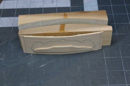
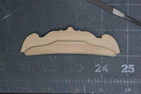
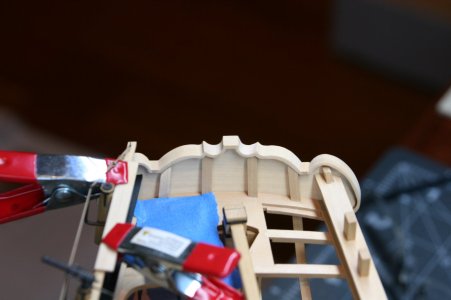
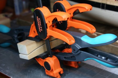
The stern of the ship is curved port to starboard so the tafferel obviously needs to reflect that shape. I had hoped this would be a time when I could use the kit-supplied parts but for some reason the tafferel components were offered flat. I did try to bend the kit parts but failed.

My solution was to make up my own tafferel using a curved form and thin layers of boxwood:
IMG_0841.JPG

IMG_0843.JPG

IMG_0844.JPG

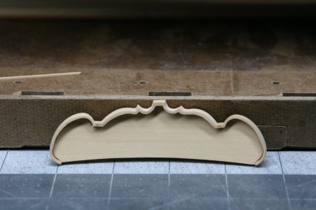
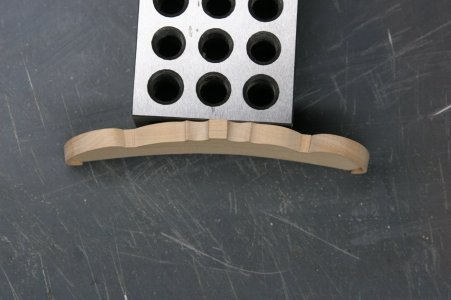
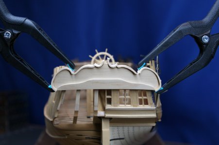
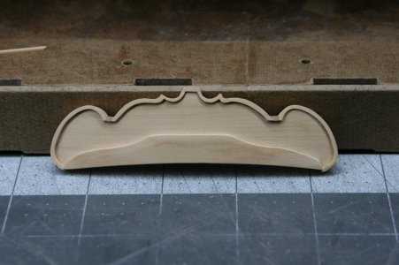
The NMM drawings clearly show a capping rail covering the top and sides of the tafferel - but it is no small request to fabricate this molding on such an ornate element. Making matters worse, the capping rail also needed to reflect the curvature of the tafferel left to right.

I used some overly wide left-over boxwood from the kit and carefully pieced together the rail:

IMG_0848.JPG

Temporarily in place so that I could place the rail parallel to the keel (and moments before the quarter rail was broken...):
IMG_0849.JPG

And now with the capping rail cleaned up:
IMG_0853.JPG

On the inboard side:

IMG_0854.JPG

And from above:

IMG_0855.JPG

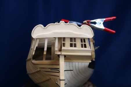
And now just sitting loosely in place for a photo:
IMG_0856.JPG

IMG_0857.JPG

IMG_0859.JPG

I can see from these photos that I need to increase the camber of the lower edge of the tafferel.

To be continued...
 
Last edited:
Building things and breaking them accidentally are part of this hobby. But when that last one happens it is always sad to hear and see.
One the other side the repairing of these parts is again fun to do and very satisfied when you succeed.
Your way to use the left overs is again an outstanding job.
 
Back
Top