Glad to help. I'll be interested in seeing the outcome. Rich (PT-2)That answers that question.
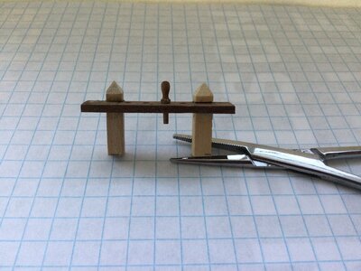
Doing a rough calculation, I would guess that the scale pin would be between 12 1/2mm and 15mm. The ones in the kit measure about 13mm.
Jan
-

Win a Free Custom Engraved Brass Coin!!!
As a way to introduce our brass coins to the community, we will raffle off a free coin during the month of August. Follow link ABOVE for instructions for entering.
-

PRE-ORDER SHIPS IN SCALE TODAY!
The beloved Ships in Scale Magazine is back and charting a new course for 2026!
Discover new skills, new techniques, and new inspirations in every issue.
NOTE THAT OUR FIRST ISSUE WILL BE JAN/FEB 2026
You are using an out of date browser. It may not display this or other websites correctly.
You should upgrade or use an alternative browser.
You should upgrade or use an alternative browser.
Krick “Alert” U.S. Cutter, 1/25 scale
- Thread starter Pathfinder65
- Start date
- Watchers 23
-
- Tags
- krick u.s.cutter alert
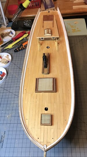
The painted deck:
Final deck color
The color using test sample #3 is slightly darker than anticipated. The Admiral thinks it’s perfect .

Jan
Final deck color
The color using test sample #3 is slightly darker than anticipated. The Admiral thinks it’s perfect .

Jan
Hi Heinrich,I concur 100% with the Admiral. It looks beautiful, Jan!
Indeed, the Admiral is a lot of help and very supportive. She has done all the fancy scissors work on my big templates. Alas, I’ve not been able to convince her to try her hand at planking a hull.
Jan
The result is a good blend and balance with the other materials. Rich (PT-2)Hi Heinrich,
Indeed, the Admiral is a lot of help and very supportive. She has done all the fancy scissors work on my big templates. Alas, I’ve not been able to convince her to try her hand at planking a hull.
Jan
The desk looks great!!Final deck color
The color using test sample #3 is slightly darker than anticipated. The Admiral thinks it’s perfect .
That is why we have admirals and serve their needs. Saying "Aye, Aye" makes like less complicated. Rich (PT-2)The desk looks great!!
Hi Jan!
Karl Heinz Marquardt, Bemastung und Takelung von Schiffen des 18. Jahrhunderts, 1994, Weltbild Verlag, page 353.
Marquardt writes: according to "Falconer" the belaying-pin is 16 inch long. The upper part of the belaying-pin is 3/7 long, the lower 4/7. The upper diameter 13/8 inch = 4.2 cm. The lower diameter 11/8 inch = 3.5 cm.
With best regards
Thomas
Hi Thomas,Hi Jan!
Karl Heinz Marquardt, Bemastung und Takelung von Schiffen des 18. Jahrhunderts, 1994, Weltbild Verlag, page 353.
Marquardt writes: according to "Falconer" the belaying-pin is 16 inch long. The upper part of the belaying-pin is 3/7 long, the lower 4/7. The upper diameter 13/8 inch = 4.2 cm. The lower diameter 11/8 inch = 3.5 cm.
With best regards
Thomas
Thank you for doing all that research. Once again rough calculations (16 inches = 406mm, 406 mm in 1:25 scale = about 16mm). Hmpf, I think I’m getting to old for this kind of mental gymnastics
The pins included with the kit are 12 mm long, with the top and bottom almost the same length. When placed in the rail one looses about two millimeters, which doesn’t leave much working room.

Jan
You will be the one who determines how much length that you want, historical or artistic freedom to present what you want associated with the pins. Just for consideration. Rich (PT-2)Hi Thomas,
Thank you for doing all that research. Once again rough calculations (16 inches = 406mm, 406 mm in 1:25 scale = about 16mm). Hmpf, I think I’m getting to old for this kind of mental gymnastics.
The pins included with the kit are 12 mm long, with the top and bottom almost the same length. When placed in the rail one looses about two millimeters, which doesn’t leave much working room.
View attachment 194506
Jan
Hi Jan!
The lower part of the belaying-pins had to be at least as thick as the thickest rope of the ship to be covered. Small ships like the Alert could also have smaller belaying-pins. They were the same on the whole ship. As Rich said, use the supplied ones. No artistry is necessary. Whether you hang the entire rope roll over the belaying-pin or just a loop that holds the rope roll depends on the space available. If the rope is attached to the pin, you can, as in the harbour, lay the rope on the deck.
Best regards
Thomas
Last edited:
Hi Jan!
The lower part of the belaying-pins had to be at least as thick as the thickest rope of the ship to be covered. Small ships like the Alert could also have smaller belaying-pins. They were the same on the whole ship. As Rich said, use the supplied ones. No artistry is necessary. Whether you hang the entire rope roll over the belaying-pin or just a loop that holds the rope roll depends on the space available. If the rope is attached to the pin, you can, as in the harbour, lay the rope on the deck.
Best regards
Thomas
Hi Thomas,
Thank you for the reply, I definitely will use the ones in the kit. There are either eight or ten pins required. Plan 2 shows two “Gedulds” with four pin holes each, while plan 2 shows one with four and the other with six holes. I’ve gone with plan 2 since there are twelve pins supplied with the kit.
My original question was a matter of curiosity, being a “novice” with this ship modeling stuff the pin just looked undersized.
Jan
The Transom:
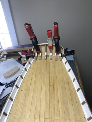
On and off this week I’ve worked on installing the Transom. Quite the problem, the Bulwark construction at the stern and the Transom don’t want to mate. With a lot of fitting, sanding and a few choice words I’ve managed to attach the Transom. The problem probably could have been avoided if I had paid more attention the Bulwark spacing at the stern. But as a novice builder I assumed that the Bulkhead extensions provided the correct angles and spacing for Bulwarks. I’m not to happy with my results but I also don’t want to try a “Red Do”. So it’s another lesson learned.

Jan
On and off this week I’ve worked on installing the Transom. Quite the problem, the Bulwark construction at the stern and the Transom don’t want to mate. With a lot of fitting, sanding and a few choice words I’ve managed to attach the Transom. The problem probably could have been avoided if I had paid more attention the Bulwark spacing at the stern. But as a novice builder I assumed that the Bulkhead extensions provided the correct angles and spacing for Bulwarks. I’m not to happy with my results but I also don’t want to try a “Red Do”. So it’s another lesson learned.

Jan
The Rudder:
An interesting note on the rudder.

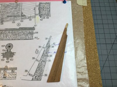
The plan rudder and the actual. All the furniture components were build from this plan using the plan as a template. BUT the rudder on the plan is not to scale. Also, I laminated the rudder blank with Mahogany instead of the Walnut supplied in the kit. The Walnut pieces that I had left varied quite a bit in color versus the Mahogany.
Jan
An interesting note on the rudder.

The plan rudder and the actual. All the furniture components were build from this plan using the plan as a template. BUT the rudder on the plan is not to scale. Also, I laminated the rudder blank with Mahogany instead of the Walnut supplied in the kit. The Walnut pieces that I had left varied quite a bit in color versus the Mahogany.
Jan
- Joined
- Jan 9, 2020
- Messages
- 10,566
- Points
- 938

Hello Jan. It is difficult to tell from that angle photograph how the transom fits, but from that shot it all look symmetrical and as if it is lining up very well. One would think that with a kit like Krick, the rudder on the plan would be to scale. Ah well ... it shows we can never assume anything!
Hi Heinrich, the photo angle is bad, but the gist of my problem was how everything lined up. I wound up drilling holes for toothpicks in the Transom supports so I could space them roughly equally and glue them in place. you can see the tops of the toothpicks if you zoom in. I couldn’t figure out any other way to hold the Transom while all the fitting was going on.Hello Jan. It is difficult to tell from that angle photograph how the transom fits, but from that shot it all look symmetrical and as if it is lining up very well. One would think that with a kit like Krick, the rudder on the plan would be to scale. Ah well ... it shows we can never assume anything!
Jan
I wouldn't worry about the toothpicks at that stage as like with teeth, every one gets cleaned up before it is done. Very nice work. I really like, if I am correct, the brass angle strips guiding the transom beam angle. Rich (PT-2)Jan, I see what you mean, but honestly, I don't think anyone would have noticed that unless you had alerted us to it.
Hi Jan!
Many wood connections were interlocked by the ship carpenters. Where this was not possible - as with the knees on the stern of the Alert - they were attached to the beam by bolts through the deck. You unconsciously did everything right!
Best regards
Thomas
Many wood connections were interlocked by the ship carpenters. Where this was not possible - as with the knees on the stern of the Alert - they were attached to the beam by bolts through the deck. You unconsciously did everything right!
Best regards
Thomas
Hi Thomas,Hi Jan!
Many wood connections were interlocked by the ship carpenters. Where this was not possible - as with the knees on the stern of the Alert - they were attached to the beam by bolts through the deck. You unconsciously did everything right!
Best regards
Thomas
Thank you for your response, I’m learning as I build. That little bit with the “knees” was a good lesson, in “how am I going to do this”.
Jan


