-

Win a Free Custom Engraved Brass Coin!!!
As a way to introduce our brass coins to the community, we will raffle off a free coin during the month of August. Follow link ABOVE for instructions for entering.
-

PRE-ORDER SHIPS IN SCALE TODAY!
The beloved Ships in Scale Magazine is back and charting a new course for 2026!
Discover new skills, new techniques, and new inspirations in every issue.
NOTE THAT OUR FIRST ISSUE WILL BE JAN/FEB 2026
You are using an out of date browser. It may not display this or other websites correctly.
You should upgrade or use an alternative browser.
You should upgrade or use an alternative browser.
Krick “Alert” U.S. Cutter, 1/25 scale
- Thread starter Pathfinder65
- Start date
- Watchers 23
-
- Tags
- krick u.s.cutter alert
It most certainly can, Jan! Well done - it looks great ... and ominous !
Hi Heinrich,
It was fun figuring out how to do the "FIX". Another documented "Do Over"
Jan
Another head scratcher:
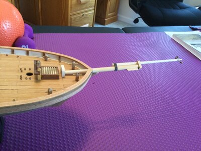
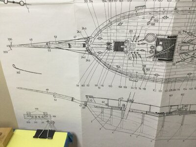
I've started to work on the Bowsprit. Looking at the plans I'm a little confused. Part number 52 (Eselshaupt) on the plan doesn't match the part in the kit.
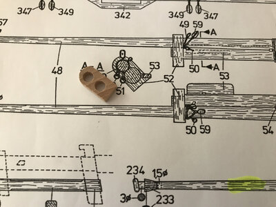
According to the plans the upper hole is about 5mm and the lower hole is about 8mm. The actual part has two holes the same diameter about 4.5 mm. Looking to the right to see how the parts should fit it looks like the ends should be reduced to fit into part 52.
It would appear to make the sprit fit, part 52 needs to be drilled, reamed to the proper sizes or I need to manufacture a replacement part.
Jan
I've started to work on the Bowsprit. Looking at the plans I'm a little confused. Part number 52 (Eselshaupt) on the plan doesn't match the part in the kit.

According to the plans the upper hole is about 5mm and the lower hole is about 8mm. The actual part has two holes the same diameter about 4.5 mm. Looking to the right to see how the parts should fit it looks like the ends should be reduced to fit into part 52.
It would appear to make the sprit fit, part 52 needs to be drilled, reamed to the proper sizes or I need to manufacture a replacement part.
Jan
The fix:
I decided to ignore the difference between the plans part 52 and the piece in the kit. I don’t think that little piece would have survived enlarging the holes. So... I did what I do best, looking at the plan the lower part of the Bowsprit ( don’t know the nautical name) is evidently recessed into the bottom 4.5mm hole, so
that was the first step.
Step two. Taper the top piece (don’t know the nautical name). Lots of elbow grease and three different kinds of sandpaper later, we have a good match to the plan.
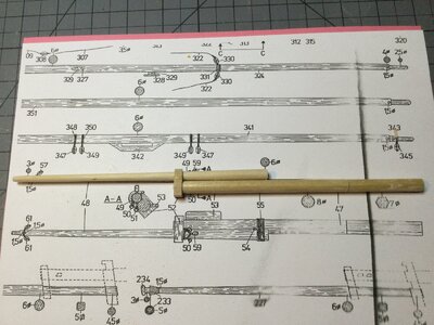
Once again the novice builder has learned something new.
Jan
I decided to ignore the difference between the plans part 52 and the piece in the kit. I don’t think that little piece would have survived enlarging the holes. So... I did what I do best, looking at the plan the lower part of the Bowsprit ( don’t know the nautical name) is evidently recessed into the bottom 4.5mm hole, so
that was the first step.
Step two. Taper the top piece (don’t know the nautical name). Lots of elbow grease and three different kinds of sandpaper later, we have a good match to the plan.

Once again the novice builder has learned something new.
Jan
Kurt Konrath
Kurt Konrath
Great work on the thing a ma gig part, or what ever it is really called!
I did notice the holes looks slightly off center, and guess you fixed that with your sanding.
I did notice the holes looks slightly off center, and guess you fixed that with your sanding.
Light Bulb Moment  :
:
I have looked at the plans over and over and just could not figure out the "DOTTED LINES" at the end of the Bowsprit. This mornings second cup of coffee must have had some smart pills in it. Because......
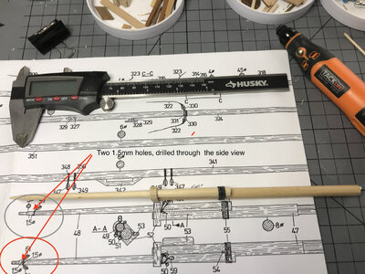
What I took to be four lines scored into the top piece are in actuality the outlines of two drilled holes. So another head scratcher put to rest.
Jan
 :
:I have looked at the plans over and over and just could not figure out the "DOTTED LINES" at the end of the Bowsprit. This mornings second cup of coffee must have had some smart pills in it. Because......

What I took to be four lines scored into the top piece are in actuality the outlines of two drilled holes. So another head scratcher put to rest.
Jan
Kurt Konrath
Kurt Konrath
I will take two cups with cream and sugar! 


Hey Jan, things are looking good. I'm hoping I have caught you soon enough before you have mounted your bowsprit/jib boom. In the above drawing there are four bobstays , two going to the jib boom and two to the bowsprit. The above drawings do not show how they are attached, usually they are attached with eyebolts/blocks, blocks/slings etc., you may want to check this out before you permanently mount the assembly as it would be much easier to do now.
As for that platform I see that there is a hole in it so it may be used in the rigging at some point, or a very precarious seat of ease!!! LOL
As for that platform I see that there is a hole in it so it may be used in the rigging at some point, or a very precarious seat of ease!!! LOL
@DonRobinson, Very good suggestion, no gluing has gone on yet. I'm puzzling over the "bobstays" part. I've blown up the drawing trying to figure out how the harness rings attach to the harness and then to bowsprit.
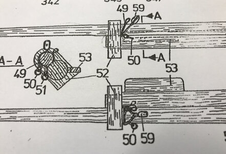
Looking at cross section "A-A" I can see how the bowsprit harness should attach (parts 50 & 51) to the bowsprit. the single block (part 59) is easy to figure out. There is no ring attached to part 49, it looks like a single loop. The confusing part is the lower drawing. I showed in my previous post how the bowsprit assembly is mounted to the hull, but the above drawing appears to be a bottom up shot and inverted leaving the little platform on the port side and not the starboard side If you mentally flip it over.
I think these head scratchers are great, makes one really have to think before the gluing starts.
Jan
Last edited:
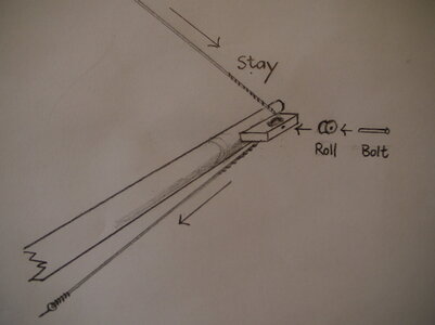
Hi Thomas,Hi Jan!
View attachment 212520
The horizontal board is as a holder for a roller, through which runs a stay. There was also on the HMS Bounty, on both sides.
Best regards
Thomas
Thank you for the information, I could not figure out it’s purpose. The plans show A small square hole up against the bowsprit but I’ve not been able to find its purpose on the rigging plan.
Jan
Wow what a day:
Today at wakeup it was snowing, an hour later it was sleeting and now its raining with the temperatures expected to drop below freezing by noon. So a good excuse to be in the shipyard.
I started rigging the gun tackle for the Carronade, I noticed that the build plan had a slight omission.
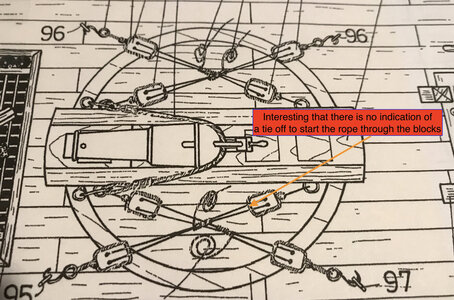
The plan doesn't show any way to attach the rope to bottom of any of the blocks. Not a problem currently but would have been if I was just starting out on my first ship building adventure.
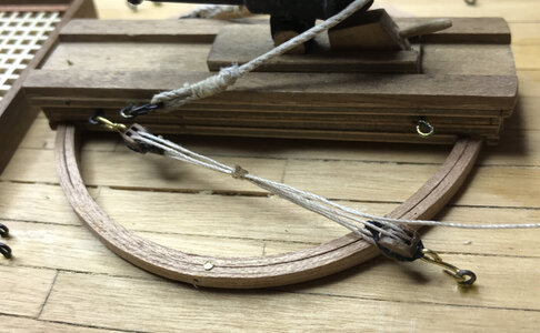
It took a couple of false starts but I managed to get a block set I liked. Only three more to do.
Jan
Today at wakeup it was snowing, an hour later it was sleeting and now its raining with the temperatures expected to drop below freezing by noon. So a good excuse to be in the shipyard.
I started rigging the gun tackle for the Carronade, I noticed that the build plan had a slight omission.

The plan doesn't show any way to attach the rope to bottom of any of the blocks. Not a problem currently but would have been if I was just starting out on my first ship building adventure.

It took a couple of false starts but I managed to get a block set I liked. Only three more to do.
Jan
Those blocks are great looking. I ordered them from Hans @Kolderstok, much better looking than the blocks supplied in the kit.That block-set looks great, Jan! In fact that whole carronade assembly is a fascinating one!That little task is also awaiting me.

Jan
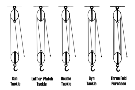
I like the way you manage to show tackles, Jan. If you don't mind, of cause, the drawings are conceptually wrong. Take a look the image how the rope tight to the block depending on the job.
View attachment 213893
Jimsky,
Thats a great graphic. I knew the rope had to attach to the end of at least one block. The drawing is definitely in error.
Jan


