Many thanks, kind sir. Much appreciated and encouraging!In Southern Germany, especially in Swabia, where I live, they say, not scolded is praised enough. But that cannot be said with you, because your work is simply too good.
-

Win a Free Custom Engraved Brass Coin!!!
As a way to introduce our brass coins to the community, we will raffle off a free coin during the month of August. Follow link ABOVE for instructions for entering.
-

PRE-ORDER SHIPS IN SCALE TODAY!
The beloved Ships in Scale Magazine is back and charting a new course for 2026!
Discover new skills, new techniques, and new inspirations in every issue.
NOTE THAT OUR FIRST ISSUE WILL BE JAN/FEB 2026
You are using an out of date browser. It may not display this or other websites correctly.
You should upgrade or use an alternative browser.
You should upgrade or use an alternative browser.
La Belle 1684 - Caf Model 1:48 by Gennaro [COMPLETED BUILD]
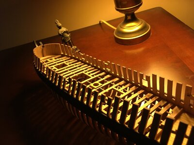
Deck framing is complete and glued in place. Does not look that much different from the last post except for those bastardly hanging knees. La Salle seems to be pleased  Here are few pictures of the current state of the model. Thanks for all the likes, comments and interest. Merry Christmas and hopefully 2021 will be a better year.
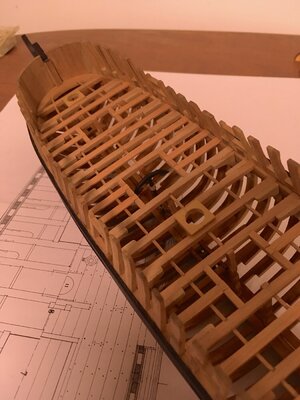
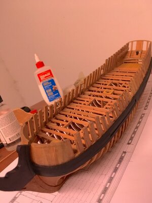
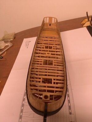
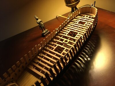


Coming along very nicely. Merry Christmas and Happy New Year to you.
I agree with Chris, she is coming really good, Very accurate and clean work.  I suspect all timber is from the kit?
Merry Christmas to you and your loved ones! Happy better year!
 I suspect all timber is from the kit?
 Merry Christmas to you and your loved ones! Happy better year!
Deck framing is complete and glued in place. Does not look that much different from the last post except for those bastardly hanging knees. La Salle seems to be pleasedHere are few pictures of the current state of the model. Thanks for all the likes, comments and interest. Merry Christmas and hopefully 2021 will be a better year.
View attachment 200245
View attachment 200246
View attachment 200248
View attachment 200249
View attachment 200250
Ha... the custodian guy again . To many issues with the Shipyard workers?
The ship is looking great !!!
Daniel
Thanks Chris, much appreciated.Coming along very nicely. Merry Christmas and Happy New Year to you.
Thanks Jim! Regarding timber, I used frames from the kit, the rest I built from scratch. What is a kit without kit bashing? I see it as opportunity to improve my skills. Who knows, maybe down the road I'll attempt to build a model completely from scratch. All the best!I agree with Chris, she is coming really good, Very accurate and clean work.I suspect all timber is from the kit?
Merry Christmas to you and your loved ones! Happy better year!
This is very nicely done - I will follow along with great interest!
Small update. Attempted to make a windlass. People with carving skills, shape the windlass
and then carve mortices. Since I'm not one of those people, I resorted to MF70.
Mortices are milled, cut into strips and glued together.
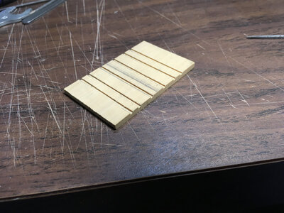
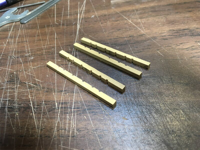
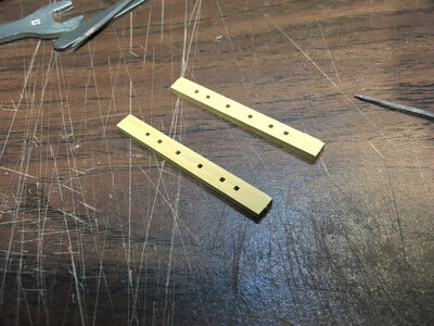
Then, mill again crosswise and lengthwise.
Long groove is for the strip of wood for two reasons: alignment (windlass will be built from 3 pieces)
and aesthetics - without a strip one would be able to see right through openings.
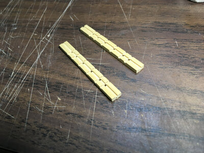
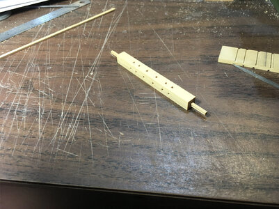
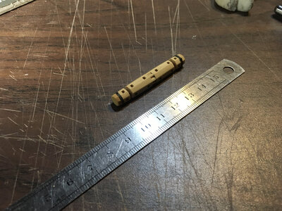
Assembled piece was cut into three pieces. Middle piece was shape into octagon and grooves
are cut using v-shape milling bit. Once assembled and glued, table saw with slitting blade
was used to cut slots for the sides. Octagon templates were transfered and carefully filed/sanded into shape.
Ends were trimmed off and octogonal pieces glued to hide the alignment strip.
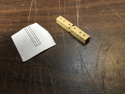
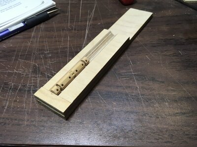
At this point, I remembered what Thomas Marocke observed - foremost part of the windlass side
cannot be installed since carlings underneath are in the way, error in plans. Too late.
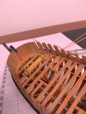
Well, my windlass will sit on carlings.
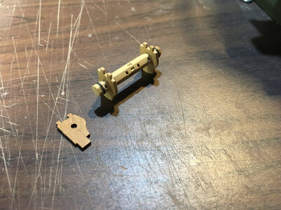
Here it is - dry fit on the deck. Thanks everybody for your comments, interest and likes. Much appreciated.
and then carve mortices. Since I'm not one of those people, I resorted to MF70.
Mortices are milled, cut into strips and glued together.


Then, mill again crosswise and lengthwise.
Long groove is for the strip of wood for two reasons: alignment (windlass will be built from 3 pieces)
and aesthetics - without a strip one would be able to see right through openings.


Assembled piece was cut into three pieces. Middle piece was shape into octagon and grooves
are cut using v-shape milling bit. Once assembled and glued, table saw with slitting blade
was used to cut slots for the sides. Octagon templates were transfered and carefully filed/sanded into shape.
Ends were trimmed off and octogonal pieces glued to hide the alignment strip.


At this point, I remembered what Thomas Marocke observed - foremost part of the windlass side
cannot be installed since carlings underneath are in the way, error in plans. Too late.
Well, my windlass will sit on carlings.

Here it is - dry fit on the deck. Thanks everybody for your comments, interest and likes. Much appreciated.

Well done, nice explanation of the process.Small update. Attempted to make a windlass. People with carving skills, shape the windlass
and then carve mortices. Since I'm not one of those people, I resorted to MF70.
Mortices are milled, cut into strips and glued together.
View attachment 202363
View attachment 202364
View attachment 202365
Then, mill again crosswise and lengthwise.
Long groove is for the strip of wood for two reasons: alignment (windlass will be built from 3 pieces)
and aesthetics - without a strip one would be able to see right through openings.
View attachment 202366
View attachment 202367
Assembled piece was cut into three pieces. Middle piece was shape into octagon and grooves
are cut using v-shape milling bit. Once assembled and glued, table saw with slitting blade
was used to cut slots for the sides. Octagon templates were transfered and carefully filed/sanded into shape.
Ends were trimmed off and octogonal pieces glued to hide the alignment strip.
View attachment 202368
View attachment 202369
View attachment 202370
At this point, I remembered what Thomas Marocke observed - foremost part of the windlass side
cannot be installed since carlings underneath are in the way, error in plans. Too late.
Well, my windlass will sit on carlings.
View attachment 202371
Here it is - dry fit on the deck. Thanks everybody for your comments, interest and likes. Much appreciated.
View attachment 202372

Brilliant idea to make windlass, I love it! I am not sure if allowed to make a suggestion, but...Here is what I am thinking; since you are building a POF model (Georgian style), and will not plank the hull, the windlass structure will be visible all the way to the keel, ...and everyone will see you are cheating: why are the 'Carrick bitt pins' didn't go to the lover beam? Check the image from the Alert book (AOTS). What do you think?
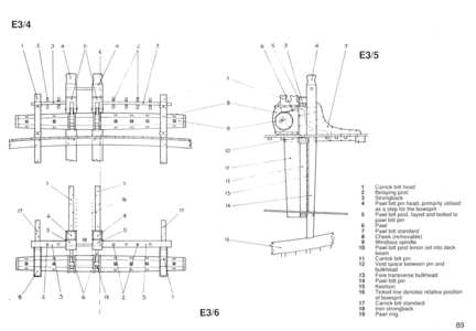

Jim, please. I'm grateful that you are interested in this little build of mine and provide constructive suggestions. To answer your question regarding Carrick bitts - I did not install them because they are not present in Boudriot's plans:Brilliant idea to make windlass, I love it! I am not sure if allowed to make a suggestion, but...Here is what I am thinking; since you are building a POF model (Georgian style), and will not plank the hull, the windlass structure will be visible all the way to the keel, ...and everyone will see you are cheating: why are the 'Carrick bitt pins' didn't go to the lover beam? Check the image from the Alert book (AOTS). What do you think?
View attachment 202413
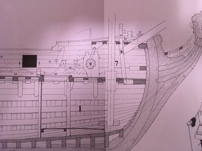
The problem with windlass is that there is an error in plans. If one builds windlass according to plans, they won't fit on the deck as shown in cross section:
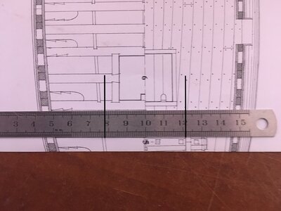
As you can see, they are positioned right on top of underlying carlings. One way to fix it is to make windlass slightly longer or smaller so it fits or, as I did, do nothing
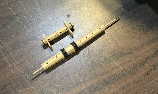
She was such a small ship, barque actually, only 10 ft longer that British longboats.
Thanks everybody and all the best to you and your families in 2021.
You are correct, hmm..., it is really strange from the engineering perspective. The 'Carrick bits' are part of the windlass and it should hold a great load on it when achor stowed. But...what do I know?!Jim, please. I'm grateful that you are interested in this little build of mine and provide constructive suggestions. To answer your question regarding Carrick bitts - I did not install them because they are not present in Boudriot's plans:
Happy New Year!!
Fully agree with you Jim, you would expect three options. Bitts al the way down to the floors, a large knee supporting towards the bow or a windlass over the full width of the hull with the windlass support in the inner bulwark.
But your work on it looks perfect, very precise.
But your work on it looks perfect, very precise.
Maarten, Boudriot actually mentions knees on the forward side in his monograph on page 66, although they do not show up on plans. There is another thing that bothers me and I'd appreciate any insight how to go about it. It is bowsprit step with foretop sheet bits. This is what we have according to plans:Fully agree with you Jim, you would expect three options. Bitts al the way down to the floors, a large knee supporting towards the bow or a windlass over the full width of the hull with the windlass support in the inner bulwark.
But your work on it looks perfect, very precise.
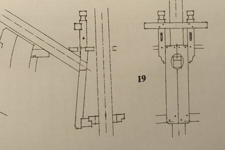
What I've seen so far, sheet bits extend all the way to the main deck beam and bowsprit step extends to the top of planking. This is the view of the main deck:
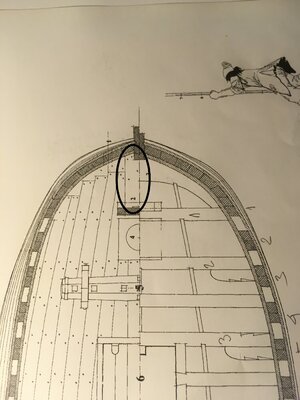
What confuses me is the circled plank - it hangs in the air?! Hopefully, I won't be violating the copyright by posting the next image. It's Olivier Gatine's La Belle and this is what it looks like:
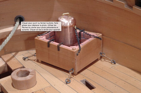
Here you can see clearly that the aft part of that plank is not resting on anything. Any ideas, suggestions? Thanks.
Hi Daniel!
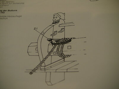
Endeavour of Captain Cook. But also still had knees (not pictured).
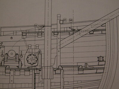
From the latest Ancre book by Jean Claude Lemineur "La Volage 1693". Plank on the deck beam and the bitts on the plank. Dowelt from below or above through the deck beam and knees. The knee of the capstan is located in the middle of the capstan and serves only to hold the brake of the drum.
I guess we have to rely on the drawings of the particular model from the books.
Best regards
Thomas

Endeavour of Captain Cook. But also still had knees (not pictured).

From the latest Ancre book by Jean Claude Lemineur "La Volage 1693". Plank on the deck beam and the bitts on the plank. Dowelt from below or above through the deck beam and knees. The knee of the capstan is located in the middle of the capstan and serves only to hold the brake of the drum.
I guess we have to rely on the drawings of the particular model from the books.
Best regards
Thomas
Last edited:
Many thanks for reply and explanation, Thomas. Some strange arrangements on these 17th century French ships. Here we see that sheet bitts are supported by knees. But, look at that gun! Smaller trucks on the left side?! I'll let this simmer for a while, before I start cutting wood.Hi Daniel!
View attachment 203340
Endeavour of Captain Cook. But also still had knees (not pictured).
View attachment 203341
From the latest Ancre book by Jean Claude Lemineur "La Volage 1693". Plank on the deck beam and the bitts on the plank. Dowelt from below or above through the deck beam and knees. The knee of the capstan is located in the middle of the capstan and serves only to hold the brake of the drum.
I guess we have to rely on the drawings of the particular model from the books.
Best regards
Thomas
Is that not just a hatch or something hiding the full truck. Nice work on the windlass!
Stupid me! You are right - it's a hatch. That's why I need to spend more time deciphering plans. Thanks!Is that not just a hatch or something hiding the full truck. Nice work on the windlass!


