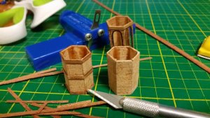
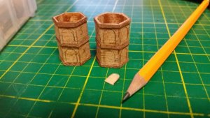
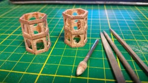
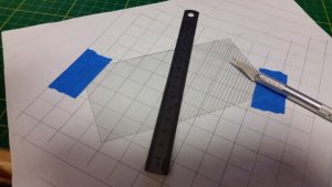
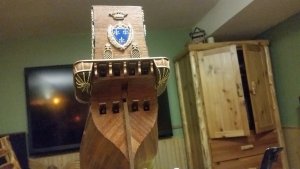
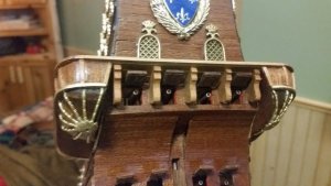
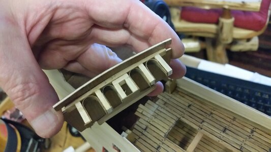
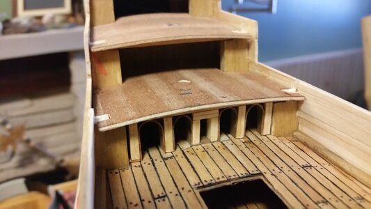
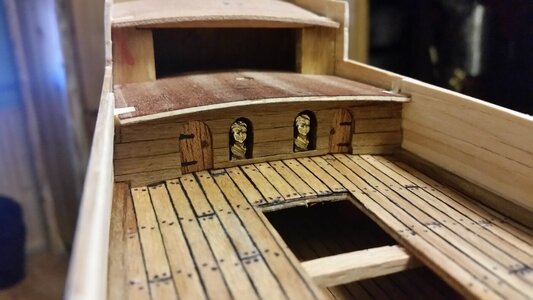
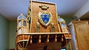
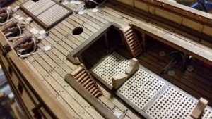
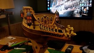
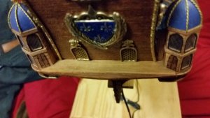
The stern gallery of the St. Louis and La Couronne were designed to convey strength using architectural motifs. The towers and the rear balcony (similar to a bridge) are very old symbols. A Roman arrow throwing catapulta even had towers and bastions on the front of the siege engine on an embossed bronze plate for the same reason.What was the function of the stern towers on the real ship?
-

Win a Free Custom Engraved Brass Coin!!!
As a way to introduce our brass coins to the community, we will raffle off a free coin during the month of August. Follow link ABOVE for instructions for entering.
-

PRE-ORDER SHIPS IN SCALE TODAY!
The beloved Ships in Scale Magazine is back and charting a new course for 2026!
Discover new skills, new techniques, and new inspirations in every issue.
NOTE THAT OUR FIRST ISSUE WILL BE JAN/FEB 2026
You are using an out of date browser. It may not display this or other websites correctly.
You should upgrade or use an alternative browser.
You should upgrade or use an alternative browser.
La Couronne Corel/scratch 1:100 First build [COMPLETED BUILD]
- Thread starter DARIVS ARCHITECTVS
- Start date
- Watchers 54
Thanks Uwek! Happy to share.I am very happy, that you decided to show us your built here in a building log - Very good work until now - many thanks for sharing with us
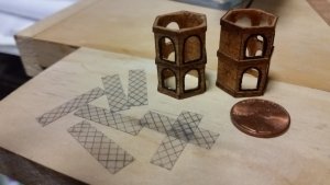
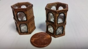
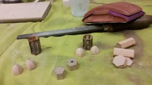
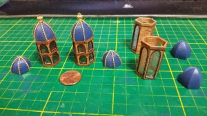
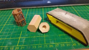
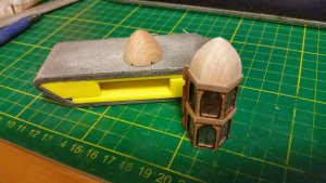
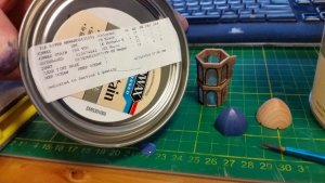
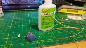
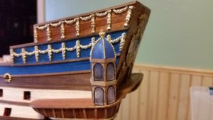
Did some work on the rearmost gallery tower bells. Decided that blue and gold was the way to go. Needed some detail, so added brass wire for contrast, and bought a bunch of brass plated crowns for each tower top. Test fitted after assembly. When all stern gallery towers are ready, a hole will be cut through the hull on both sides for the wiring and LED lights, and the LED's will be arranged inside the enclosure between the two towers on each side of the ship, such that light streams through the towers to the outside. For a 1:100 scale shape, the threshold at which you limit the details is much smaller that on a larger, 1 meter long model, and I have to choose how much detail is worth installing. Making an entire stern gallery interior for this ship would largely go unappreciated. Fat fingers also have their limits. Besides, I have to save up some enthusiasm for the Deagostini Sovereign of the Seas I have it two big boxes awaiting construction next.


Last edited:
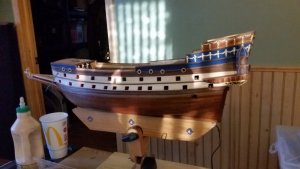
The last 48 hours were devoted to getting a part of the ship that always had me concerned with regard to how well it would turn out; the stern and side galleries. After finishing the towers, including the two bow towers, it was time to tackle the side galleries. One of the 6 circuits off the lighting control board was reserved for the side gallery lights. All the light circuits were programmed to flicker little, simulating torch or lamp light. It sort of brings a little life to an otherwise static model. I wish I had the talent to make human figures, because Doris Obručová's HMS Sovereign of the Seas is a living ship, with lots of human figures (plus a dog) shown actively doing things on the ship. Sadly, 1:100 scale sailor figures are quite rare, having only found 15 1770's American sailor figures available in my search.
But I digress. The side galleries are done! The lighting is nice. I went with blue roofs on the side galleries, and the railings on the fore peak will be changed to be more similar to Dutch style. There are more details to add to the stern besides the rudder, and all the deck details like railings and posts need to be done. I have to fight the ever-present urge to rush things. Best to slow and super-detail everything I can, because the end result will be worth it.
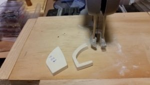
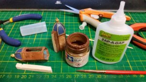
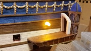
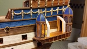
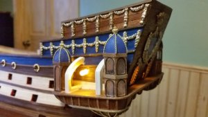
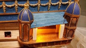
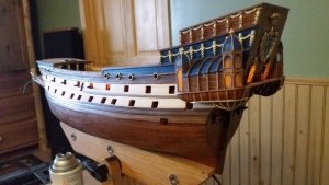
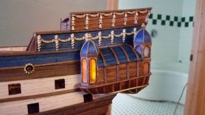
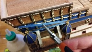
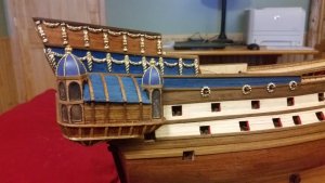
But I digress. The side galleries are done! The lighting is nice. I went with blue roofs on the side galleries, and the railings on the fore peak will be changed to be more similar to Dutch style. There are more details to add to the stern besides the rudder, and all the deck details like railings and posts need to be done. I have to fight the ever-present urge to rush things. Best to slow and super-detail everything I can, because the end result will be worth it.


Last edited:
That looks great Kurt.I like the way the glazing is lit indirectly,very subtle.
Kind Regards
Nigel
Kind Regards
Nigel
Thanks Nigel!That looks great Kurt.I like the way the glazing is lit indirectly,very subtle.
Kind Regards
Nigel
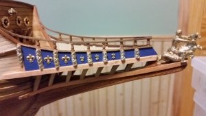
I was thinking for days over what to do with the prow of the ship since there are so many interpretations, varying between the Mantua version, the Corel version, and the one depicted in paintings of the St. Louis. I opted to go with one similar to the St. Louis put using the lower foundation from the Corel kit as a base, and base the style on a paper model made by Jan, aka Jano 100, which is similar to the St. Louis.
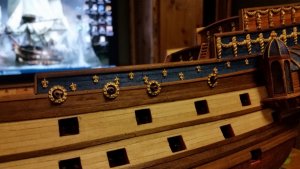
After that, it was time to add some decorations to the starboard side, made up of fluer-de-lis on the sides of the ship and on the prow, and adapting some of the Corel human-like figures and putting them on the prow. I think I'll work on the bow towers after duplicating the decorations on the port side.
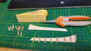
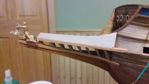
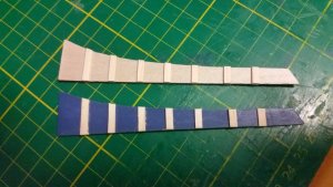
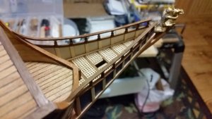
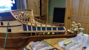
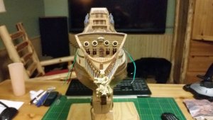
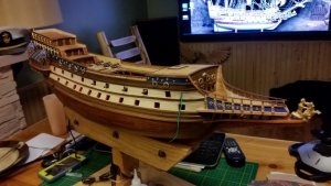
After that, it was time to add some decorations to the starboard side, made up of fluer-de-lis on the sides of the ship and on the prow, and adapting some of the Corel human-like figures and putting them on the prow. I think I'll work on the bow towers after duplicating the decorations on the port side.


Last edited:
Started on the rudder today. Since the stern post was not layered with mahogany, the rudder will not be either, in order to make it the same thickness as the rudder post. The rear, top, and bottom surfaces were overlaid with sapele wood which matched the grain of the mahogany sides of the rudder, and the inside edge was simply stained dark with walnut stain. The hinges provided needed to be resized using a vise to make them narrower and fit both the stern post and the rudder. The rudder chain, which provides for an alternate method of steering, was blacked as well as the cut edges of the hinges as well as some nails, a few cannon port hinged, and a few brass shafts that will probably not be used in favor of using brass pins on the cannon port hinges.
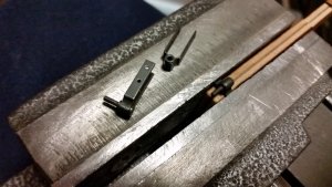
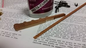
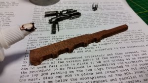
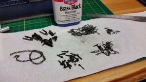


The rudder hinges were cut to the correct lengths to fit the rudder and the stern post. More nail holes needed to be drilled into the tiny hinges. The hinges provided with the kit were the wrong length and had the holes in the wrong places for this ship, being as they are standard Corel parts for several models.
After being customized, the hinges were fitted to the rudder. Tiny black pins were shortened with a side cutter and the holes were pre-drilled with a micro-drill bit in a Dremel tool to prevent the wood from splitting. Each nail had CA adhesive applied before being tapped into the rudder with a small tack hammer and held with small needle nosed pliers. The same technique was used to attach the hinges to the hull.
The emergency steering chain was blackened to make it look like iron and it was attached to eyelets glued into the rudder similar to the nails that hold the hinges on. The decoration was slipped over the chain and the chain was glued into the holes in the transom. When dry, the decorative chain portals were also glued to the transom.
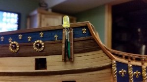
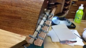
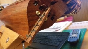
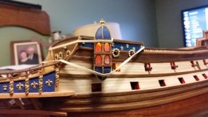
Installation of the bow towers is begun. I read somewhere that these could have been used for crossbowman during close ship-to-ship combat as well as affording a place to allow a great vantage point for observation from the bow. They are particular of French and Dutch ships of this early period. The port tower was completed today, and the starboard one will be installed later. The tower assemblies were completed earlier and not the arduous process of making the mounts that attach them to the hull needed to be done. I took some mahogany and cut two thin strips that were custom filed to fit the hull on one side, then to mate to the tower on the other. Thin strips of mahogany were cut with a scissors to make the top and bottom sides of the mount. Lots of test was done to make sure the mount fit the contour of the hull and wales and the tower.
The side of the mount were CA glued to the hull after studying the blueprints for correct position. The electrical wires for the yellow LED were cut to a shorter length to allow them to fit properly in the mount. A hole was cut into the side of the tower for insertion of the LED. The LED fits into a hole bored into the top bell of the tower, such that the light is dimmed a bit by the hole which the LED is inserted, making the tower lit from above by less direct light. That way, I won't have to paint the LED to dim the light. A test fit of the LED in the tower shows how much light it produces in this configuration.
The LED is connected to the wiring using two solder & seal connectors that had the seal portion cut off, leaving only the solder part of the connector. There was not enough space in the mount for the entire connector, and the seals are not needed anyway. A heat gun was used to melt the solder and make the connections. I like these connectors! They take the frustration out of soldering. The LED was test fitted into the mount. Then the LED was glued into the top of the tower bell with CA glue, and the tower attached to the mount.
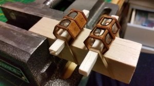
When that dried, the tower was attached to the mount with PVA (Titebond III) and held with rubber bands until it dried. I'm very pleased with how the lighting turned out.
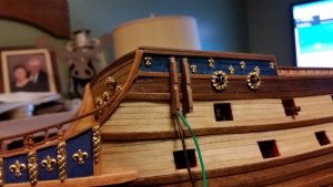
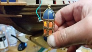
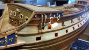
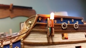


Last edited:
Looking very good - many thanks for sharing
Nice work and a beautiful model. Looking forward to following this build.
Hello everyone!
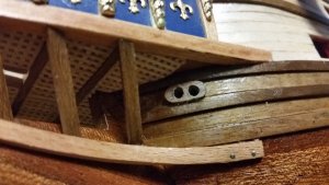
Today the anchor line hawse pipes were installed on both sides of the bow. I had to remove one of the prow supports on each side, closest to the hull, because they posed an obstruction which would contact or foul the anchor lines. The pieces were cut from walnut, two holes drilled in each, filed to shape and attached to the hull. Then, the hawse pipe holes were drilled deep into the hull.
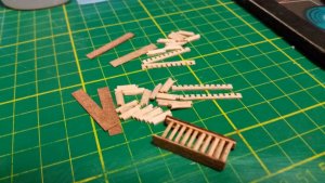
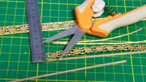
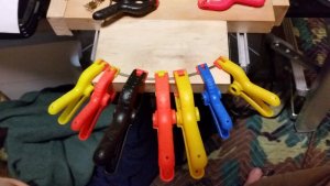
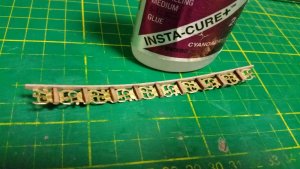
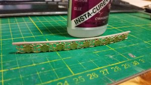
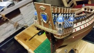
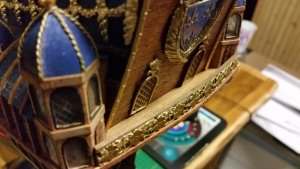
The stern gallery is finally completed with the construction of the stern balcony railing. Instead of the plain flat wood railing provided by the kit, inspiration for a custom design was provided by another builder of this model. Decorative brass strip 10 mm wide was cut, and the center section of the strip was assembled into a gunwale and railing for the balcony using pillars and rail made from walnut. The top rail of walnut was shaped in an arc to match the balcony by soaking it in hot water, clamping it to shape and allowing it to dry. The brass was bent into an arc and helped maintain the top rail of walnut from returning to straight as the CA glue set. The finished piece was filed to final trim and attached to the stern balcony with CA glue. The stern gallery is now complete, and the last piece adds a lot of detail to the overall appearance. Note that persons walking the balcony now have enough room to walk without banging their heads on the transom. Too often models are built with features that would not be truly functional in full scale. Most interpretations of the rear balcony of La Couronne are extremely narrow.


Question: If La Couronne and other galleons did not have catheads, what was used to hoist the anchors up to store them on the foremast channels?


