This is completely a textbook that answered many of my doubts about rope making
-

Win a Free Custom Engraved Brass Coin!!!
As a way to introduce our brass coins to the community, we will raffle off a free coin during the month of August. Follow link ABOVE for instructions for entering.
-

PRE-ORDER SHIPS IN SCALE TODAY!
The beloved Ships in Scale Magazine is back and charting a new course for 2026!
Discover new skills, new techniques, and new inspirations in every issue.
NOTE THAT OUR FIRST ISSUE WILL BE JAN/FEB 2026
You are using an out of date browser. It may not display this or other websites correctly.
You should upgrade or use an alternative browser.
You should upgrade or use an alternative browser.
La Créole 1827 by archjofo - Scale 1/48 - French corvette
- Joined
- Nov 10, 2019
- Messages
- 479
- Points
- 373

@Steef66
Hello Stephan,
Thanks for your contribution.
I think you'll agree with what follows.
@caf
Thank you for your interest.
Here's the continuation ...
Also, many thanks to everyone else for the likes.
Continuation: Fore yard – Leech lines and bunt lines / Cargo-fonds et cargo-boulines
I'm still wondering how the leech and bunt lines were secured without sails to prevent them from slipping off the blocks. After further research, I've now come across a stopper knot called the figure-eight knot (French: Noeud de huit).
This seems to be the ultimate stopper knot, especially well-suited for temporarily tying lines, such as leech and bunt lines without sails. When attaching the sails, it can be easily untied, even when attached to a block. It's stronger than a bowline and easier to control.
This is also how it is described in principle in "The Ashley Book of Knots" with reference to the Lever's Sheet , as the following excerpts show.

Source: The Ashley Book of Knots
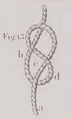
Source: The young sea officer's sheet anchor; Darcey Lever, 1813
The French call this knot a "noeud de huit."
Once again, as so often with specific, detailed questions, G. Delacroix provided me with expert support. When I asked about the figure-eight knot in connection with leech and bunt lines, he told me that these knots are generally referred to as "stopper knots" in historical descriptions, and he could imagine that the figure-eight knot would have been quite suitable for this purpose and that its use is not uncommon.
As for L'Egyptienne 1799, the loop-shaped knots should be viewed with skepticism, as the rigging is likely questionable in terms of restoration.
In summary, I have come to the conclusion that I consider the figure-eight knot to be a completely historically credible variant for my model and will implement it accordingly.
To be continued...
Hello Stephan,
Thanks for your contribution.
I think you'll agree with what follows.
@caf
Thank you for your interest.
Here's the continuation ...
Also, many thanks to everyone else for the likes.
Continuation: Fore yard – Leech lines and bunt lines / Cargo-fonds et cargo-boulines
I'm still wondering how the leech and bunt lines were secured without sails to prevent them from slipping off the blocks. After further research, I've now come across a stopper knot called the figure-eight knot (French: Noeud de huit).
This seems to be the ultimate stopper knot, especially well-suited for temporarily tying lines, such as leech and bunt lines without sails. When attaching the sails, it can be easily untied, even when attached to a block. It's stronger than a bowline and easier to control.
This is also how it is described in principle in "The Ashley Book of Knots" with reference to the Lever's Sheet
 , as the following excerpts show.
Source: The Ashley Book of Knots

Source: The young sea officer's sheet anchor; Darcey Lever, 1813
The French call this knot a "noeud de huit."
Once again, as so often with specific, detailed questions, G. Delacroix provided me with expert support. When I asked about the figure-eight knot in connection with leech and bunt lines, he told me that these knots are generally referred to as "stopper knots" in historical descriptions, and he could imagine that the figure-eight knot would have been quite suitable for this purpose and that its use is not uncommon.
As for L'Egyptienne 1799, the loop-shaped knots should be viewed with skepticism, as the rigging is likely questionable in terms of restoration.
In summary, I have come to the conclusion that I consider the figure-eight knot to be a completely historically credible variant for my model and will implement it accordingly.
To be continued...
Last edited:
Kurt Konrath
Kurt Konrath
I have done sailing in small boats and we used that knot to keep the ends of lines from pulling thru pullies on main sheet and jibs, which is why it was called a stopper knot.
- Joined
- Aug 8, 2019
- Messages
- 5,584
- Points
- 738

I agree, you have permission to use that knot.I think you'll agree with what follows.
Ashley explains it all, just have to find it.
Nice to see here the figure-eight knot, Johann. In (mountain) climbing we often use the (double) eight to secure the rope to your climbing harness.@Steef66
Hello Stephan,
Thanks for your contribution.
I think you'll agree with what follows.
@caf
Thank you for your interest.
Here's the continuation ...
Also, many thanks to everyone else for the likes.
Continuation: Fore yard – Leech lines and bunt lines / Cargo-fonds et cargo-boulines
I'm still wondering how the leech and bunt lines were secured without sails to prevent them from slipping off the blocks. After further research, I've now come across a stopper knot called the figure-eight knot (French: Noeud de huit).
This seems to be the ultimate stopper knot, especially well-suited for temporarily tying lines, such as leech and bunt lines without sails. When attaching the sails, it can be easily untied, even when attached to a block. It's stronger than a bowline and easier to control.
This is also how it is described in principle in "The Ashley Book of Knots" with reference to the Lever's Sheet, as the following excerpts show.
View attachment 523716
Source: The Ashley Book of Knots
View attachment 523717
Source: The young sea officer's sheet anchor; Darcey Lever, 1813
The French call this knot a "noeud de huit."
Once again, as so often with specific, detailed questions, G. Delacroix provided me with expert support. When I asked about the figure-eight knot in connection with leech and bunt lines, he told me that these knots are generally referred to as "stopper knots" in historical descriptions, and he could imagine that the figure-eight knot would have been quite suitable for this purpose and that its use is not uncommon.
As for L'Egyptienne 1799, the loop-shaped knots should be viewed with skepticism, as the rigging is likely questionable in terms of restoration.
In summary, I have come to the conclusion that I consider the figure-eight knot to be a completely historically credible variant for my model and will implement it accordingly.
To be continued...
Regards, Peter
- Joined
- Nov 10, 2019
- Messages
- 479
- Points
- 373

There's not much model building going on at the moment.
Summer, house building for juniors, gardening, and so on...
So here's a quick summer lull filler
Before we continue, I would like to thank you all for your support.
Note on the routing of the lower yard lifts
The following topic will be familiar to many experienced model builders who have already rigged a historic sailing ship, and it’s been discussed in this forum before.
On my corvette, the same phenomenon appeared when belaying the lifts of the unbraced foreyard, as shown in the photo below:
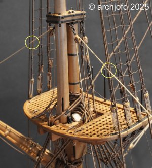
The lifts lightly touch the forward topmast shrouds. Since this might unsettle some beginners, I’ll briefly summarize why this happens.
Lifts are usually led from the center of the mast cap -i.e. behind the topmast- out to the yard arms. The foreyard hangs in front of the lower mast, and so lies beneath the topmast. In side view, the forward topmast shrouds run verticaly up from the lower mast to the topmast head.
Because of this geometry, the lower yard lifts inevitably come into contact with the forward topmast shrouds even when the yard is unbraced, and certainly when it’s braced in. Accordingly, the forward topmast shrouds are always served against chafe.
This is not an error; it’s simply a result of the rigging’s geometry and layout.
Summer, house building for juniors, gardening, and so on...
So here's a quick summer lull filler
Before we continue, I would like to thank you all for your support.
Note on the routing of the lower yard lifts
The following topic will be familiar to many experienced model builders who have already rigged a historic sailing ship, and it’s been discussed in this forum before.
On my corvette, the same phenomenon appeared when belaying the lifts of the unbraced foreyard, as shown in the photo below:

The lifts lightly touch the forward topmast shrouds. Since this might unsettle some beginners, I’ll briefly summarize why this happens.
Lifts are usually led from the center of the mast cap -i.e. behind the topmast- out to the yard arms. The foreyard hangs in front of the lower mast, and so lies beneath the topmast. In side view, the forward topmast shrouds run verticaly up from the lower mast to the topmast head.
Because of this geometry, the lower yard lifts inevitably come into contact with the forward topmast shrouds even when the yard is unbraced, and certainly when it’s braced in. Accordingly, the forward topmast shrouds are always served against chafe.
This is not an error; it’s simply a result of the rigging’s geometry and layout.
- Joined
- Aug 8, 2019
- Messages
- 5,584
- Points
- 738

Railroad sinnit. I was searching for the right name when I see your post Johann. There was a picture of them on Facebook I believe, where a woman was making them to attached them to the ropes to avoid chave. I should have save it. And today, when I was looking for robands (for my sails of the PW) I seen them on page 552 of Ashley's book of knots. Maybe you can use this info, because not all ropes where served, but needed protection anyway.And this is an interesting method or detail.
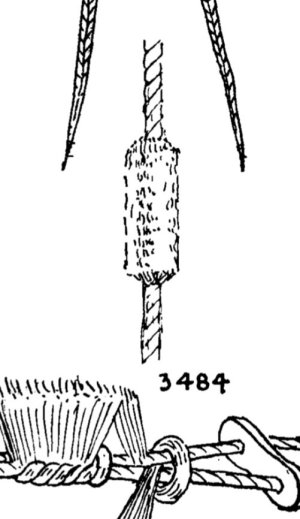

The "railroad sennet" illustrated is the type of sennet (chain of knots) used to make baggywrinkle. Separate unlaid-strands are cow-hitched around two standing lengths of small stuff until a long, bushy fringe is created. That sennet is then wrapped around an object to form a bushy cylinder that insulates lines and sails vulnerable to chafe away from the stationary chafing source as necessary.
Forward shrouds were customarily served to prevent chafing of fiber rope shrouds by running lines as Johann correctly stated. "Baggywrinkle," (#3484 in Ashley's illustrated above) is chafing gear which is fastened not only to standing rigging, but also to any other stationary thing, to prevent chafing damage primarily to the sails. Serving protects the thing to which it's fastened. Baggywrinkle protects something other than that to which it's fastened. Baggywrinkle can only be fastened to running rigging where the baggywrinkle will not be required to run through a sheave through which, obviously, it cannot fit. An example of this would be on a topping lift below the point where the lift would ever need to run through its block.
Worming, parceling, and serving was also applied to fiber standing rigging to protect it from weathering and to give it a longer useful lifespan. Moreover, the thick tar bedding beneath the parceling and the tar coating over the service imparted a large measure of waterproofness which minimized the need for adjusting the standing rigging tension between wet and dry cycles. Later, when metal cable supplanted fiber standing rigging, worming, parceling, and serving, with a bedding of thick white lead paste beneath the parceling, served to preserve iron wire from corrosion. With the advent of galvanized cable, there was no need for worming, parceling, or serving, nor for protecting the standing rigging from chafe, but, rather, sails and running rigging required protection from chafe caused by the bare metal standing rigging. At that point, apparently, baggywrinkle came into use to provide a soft buffer in areas where running rigging and sails contacted the standing rigging. Galvanized steel was a creature of the Industrial Revolution and, although the process was known previously, did not begin to come into widespread use until after 1800. It would appear that galvanized wire standing rigging began to be used after the mid-1800's and had become predominant by the beginning of the 20th Century, although the exact date of its first use for ships' rigging is unknown to me. As explained, it appears baggywrinkle came into use contemporaneously with the use of galvanized standing rigging.
According to the O.E.D., the term "baggywrinkle" is unknown in print prior to 1867 when it was used to describe a type of packing material, rather than a sennet used for chafe protection. The nautical term, "baggywrinkle," used to describe the referenced chaffing gear, did not appear in print until 1927. I would recommend caution before anybody used it on a model of a sailing ship of any period prior to 1867 without researching its contemporaneity.
Top half: a length of railroad sennet made up of synthetic strands of line:
Bottom half: railroad sennet wrapped around a core to form baggywrinkle:
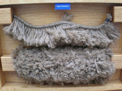
Baggywrinkle in place on a shroud:
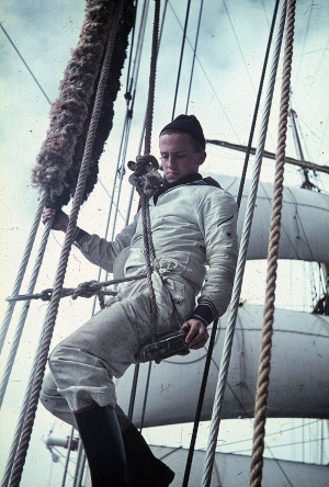
Forward shrouds were customarily served to prevent chafing of fiber rope shrouds by running lines as Johann correctly stated. "Baggywrinkle," (#3484 in Ashley's illustrated above) is chafing gear which is fastened not only to standing rigging, but also to any other stationary thing, to prevent chafing damage primarily to the sails. Serving protects the thing to which it's fastened. Baggywrinkle protects something other than that to which it's fastened. Baggywrinkle can only be fastened to running rigging where the baggywrinkle will not be required to run through a sheave through which, obviously, it cannot fit. An example of this would be on a topping lift below the point where the lift would ever need to run through its block.
Worming, parceling, and serving was also applied to fiber standing rigging to protect it from weathering and to give it a longer useful lifespan. Moreover, the thick tar bedding beneath the parceling and the tar coating over the service imparted a large measure of waterproofness which minimized the need for adjusting the standing rigging tension between wet and dry cycles. Later, when metal cable supplanted fiber standing rigging, worming, parceling, and serving, with a bedding of thick white lead paste beneath the parceling, served to preserve iron wire from corrosion. With the advent of galvanized cable, there was no need for worming, parceling, or serving, nor for protecting the standing rigging from chafe, but, rather, sails and running rigging required protection from chafe caused by the bare metal standing rigging. At that point, apparently, baggywrinkle came into use to provide a soft buffer in areas where running rigging and sails contacted the standing rigging. Galvanized steel was a creature of the Industrial Revolution and, although the process was known previously, did not begin to come into widespread use until after 1800. It would appear that galvanized wire standing rigging began to be used after the mid-1800's and had become predominant by the beginning of the 20th Century, although the exact date of its first use for ships' rigging is unknown to me. As explained, it appears baggywrinkle came into use contemporaneously with the use of galvanized standing rigging.
According to the O.E.D., the term "baggywrinkle" is unknown in print prior to 1867 when it was used to describe a type of packing material, rather than a sennet used for chafe protection. The nautical term, "baggywrinkle," used to describe the referenced chaffing gear, did not appear in print until 1927. I would recommend caution before anybody used it on a model of a sailing ship of any period prior to 1867 without researching its contemporaneity.
Top half: a length of railroad sennet made up of synthetic strands of line:
Bottom half: railroad sennet wrapped around a core to form baggywrinkle:

Baggywrinkle in place on a shroud:

And all this time I thought I was baggy-wrinkle. Can’t be, though, because I tend to CAUSE chafing among those around me…
Thank you, Bob, for that truly interesting piece of maritime knowledge!The "railroad sennet" illustrated is the type of sennet (chain of knots) used to make baggywrinkle. Separate unlaid-strands are cow-hitched around two standing lengths of small stuff until a long, bushy fringe is created. That sennet is then wrapped around an object to form a bushy cylinder that insulates lines and sails vulnerable to chafe away from the stationary chafing source as necessary.
Forward shrouds were customarily served to prevent chafing of fiber rope shrouds by running lines as Johann correctly stated. "Baggywrinkle," (#3484 in Ashley's illustrated above) is chafing gear which is fastened not only to standing rigging, but also to any other stationary thing, to prevent chafing damage primarily to the sails. Serving protects the thing to which it's fastened. Baggywrinkle protects something other than that to which it's fastened. Baggywrinkle can only be fastened to running rigging where the baggywrinkle will not be required to run through a sheave through which, obviously, it cannot fit. An example of this would be on a topping lift below the point where the lift would ever need to run through its block.
Worming, parceling, and serving was also applied to fiber standing rigging to protect it from weathering and to give it a longer useful lifespan. Moreover, the thick tar bedding beneath the parceling and the tar coating over the service imparted a large measure of waterproofness which minimized the need for adjusting the standing rigging tension between wet and dry cycles. Later, when metal cable supplanted fiber standing rigging, worming, parceling, and serving, with a bedding of thick white lead paste beneath the parceling, served to preserve iron wire from corrosion. With the advent of galvanized cable, there was no need for worming, parceling, or serving, nor for protecting the standing rigging from chafe, but, rather, sails and running rigging required protection from chafe caused by the bare metal standing rigging. At that point, apparently, baggywrinkle came into use to provide a soft buffer in areas where running rigging and sails contacted the standing rigging. Galvanized steel was a creature of the Industrial Revolution and, although the process was known previously, did not begin to come into widespread use until after 1800. It would appear that galvanized wire standing rigging began to be used after the mid-1800's and had become predominant by the beginning of the 20th Century, although the exact date of its first use for ships' rigging is unknown to me. As explained, it appears baggywrinkle came into use contemporaneously with the use of galvanized standing rigging.
According to the O.E.D., the term "baggywrinkle" is unknown in print prior to 1867 when it was used to describe a type of packing material, rather than a sennet used for chafe protection. The nautical term, "baggywrinkle," used to describe the referenced chaffing gear, did not appear in print until 1927. I would recommend caution before anybody used it on a model of a sailing ship of any period prior to 1867 without researching its contemporaneity.
Top half: a length of railroad sennet made up of synthetic strands of line:
Bottom half: railroad sennet wrapped around a core to form baggywrinkle:
View attachment 533897
Baggywrinkle in place on a shroud:
View attachment 533898
- Joined
- Nov 10, 2019
- Messages
- 479
- Points
- 373

Photo Book - LA CRÉOLE CORVETTE DE 24 BOUCHES À FEU 1827
DU L’INGÉNIEUR LEROUX
Sometimes a project needs a little break – and sometimes you need something to remind you why you started it.
Since I can't currently continue working on the running rigging of my French corvette, La Créole, for personal reasons (my son's house building and a few age-related aches and pains...), I've created a photo book: as a source of motivation, a look back, and a look ahead.
In this video, I take you on a little journey through this book – a piece of model building history in pictures.
DU L’INGÉNIEUR LEROUX
Sometimes a project needs a little break – and sometimes you need something to remind you why you started it.
Since I can't currently continue working on the running rigging of my French corvette, La Créole, for personal reasons (my son's house building and a few age-related aches and pains...), I've created a photo book: as a source of motivation, a look back, and a look ahead.
A nice overview of the last years, Johann. A collection of nicely pictures of your detailed work.Photo Book - LA CRÉOLE CORVETTE DE 24 BOUCHES À FEU 1827
DU L’INGÉNIEUR LEROUX
Sometimes a project needs a little break – and sometimes you need something to remind you why you started it.
Since I can't currently continue working on the running rigging of my French corvette, La Créole, for personal reasons (my son's house building and a few age-related aches and pains...), I've created a photo book: as a source of motivation, a look back, and a look ahead.
In this video, I take you on a little journey through this book – a piece of model building history in pictures.
Regards, Peter
Beautiful JohanPhoto Book - LA CRÉOLE CORVETTE DE 24 BOUCHES À FEU 1827
DU L’INGÉNIEUR LEROUX
Sometimes a project needs a little break – and sometimes you need something to remind you why you started it.
Since I can't currently continue working on the running rigging of my French corvette, La Créole, for personal reasons (my son's house building and a few age-related aches and pains...), I've created a photo book: as a source of motivation, a look back, and a look ahead.
In this video, I take you on a little journey through this book – a piece of model building history in pictures.
- Joined
- Nov 10, 2019
- Messages
- 479
- Points
- 373

@Peter Voogt oogt
@Bob Cleek
@shota70
@Bobby K.
@GrantTyler
@Mirek
Hello colleagues,
I would like to thank you all for the kind words about my photo book. Of course, thanks also go to the likes.
After the Summer Break – Continuing My Build Log
The days are growing shorter, the world outside is quieter—and with autumn comes a renewed passion for model building. After a brief creative pause, I’m looking forward to resuming work on my French corvette La Créole.
As a starting point, I’ve recently focused on clarifying the belaying points in the foredeck area, in order to complete the rigging of the fore yard as well as the jibboom and flying jibboom. In this context, I’ve created two illustrations (based on cropped images of the original model and excerpts from J. Boudriot’s monograph), which I’d like to share here.
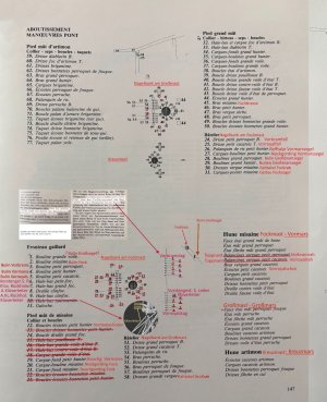
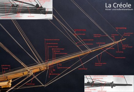
These sketches are not yet complete, but they serve as a foundation for further development and offer a glimpse into the research that preceded this stage. Once again, working through these details has shown how multifaceted and rewarding the engagement with historical sources, technical drawings, and contemporary models can be—and how much it contributes to the vitality of a project like this.
One aspect that remains unclear to me is the routing of the mainsail bowlines, as depicted in Boudriot’s monograph. According to his illustration, the bowlines are led forward over the foredeck—a solution I hadn’t encountered before. Based on my current understanding—and after reviewing several period models—bowlines are typically belayed aft of the foremast.
Routing them over the foredeck seems not only unusual but also technically problematic, as it could potentially interfere with the foremast rigging. This point therefore remains unresolved and will require further investigation.
I look forward to exchanging ideas with you and am eager to hear your thoughts and suggestions regarding the sketches I’ve shared.
@Bob Cleek
@shota70
@Bobby K.
@GrantTyler
@Mirek
Hello colleagues,
I would like to thank you all for the kind words about my photo book. Of course, thanks also go to the likes.
After the Summer Break – Continuing My Build Log
The days are growing shorter, the world outside is quieter—and with autumn comes a renewed passion for model building. After a brief creative pause, I’m looking forward to resuming work on my French corvette La Créole.
As a starting point, I’ve recently focused on clarifying the belaying points in the foredeck area, in order to complete the rigging of the fore yard as well as the jibboom and flying jibboom. In this context, I’ve created two illustrations (based on cropped images of the original model and excerpts from J. Boudriot’s monograph), which I’d like to share here.


These sketches are not yet complete, but they serve as a foundation for further development and offer a glimpse into the research that preceded this stage. Once again, working through these details has shown how multifaceted and rewarding the engagement with historical sources, technical drawings, and contemporary models can be—and how much it contributes to the vitality of a project like this.
One aspect that remains unclear to me is the routing of the mainsail bowlines, as depicted in Boudriot’s monograph. According to his illustration, the bowlines are led forward over the foredeck—a solution I hadn’t encountered before. Based on my current understanding—and after reviewing several period models—bowlines are typically belayed aft of the foremast.
Routing them over the foredeck seems not only unusual but also technically problematic, as it could potentially interfere with the foremast rigging. This point therefore remains unresolved and will require further investigation.
I look forward to exchanging ideas with you and am eager to hear your thoughts and suggestions regarding the sketches I’ve shared.
- Joined
- Aug 8, 2019
- Messages
- 5,584
- Points
- 738

The bowlines run completely differently than on my 1600 galleon. Or for my Prince William. But I do see a similarity in belaying the mainsail bowline on the forecastle. (On the Spanish galleon on the foot of the bowmast.)
On my ship it will run along the main shroud of the fok. Through a chuck that is attached on the shroud to the jib and back. On the PW I will use a snatch-block on the foot of the Fok.
Maybe this info is a little help to you. (I used Peter Kirsch Die Galleonen for the rigging) but like I said, a little help, there is almost 200 years between both ships.
Edit.
It was Anderson on page 165 who discribes the lead of the bowline for ships like the Galleon and the PW.
Pictures say more then words.
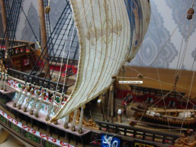
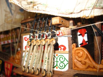
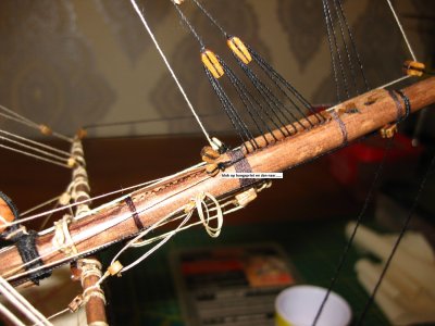
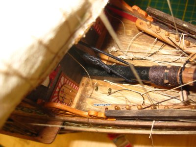
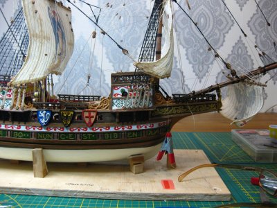
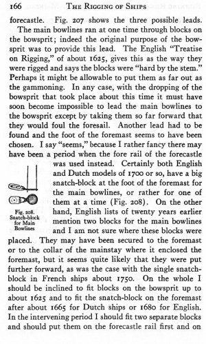
Interresting part I discovered of the bowlines of a square rigger is that they are bring out as far as possible to the stem. Necessary to use the bowlines. I think that this fact never changed in the years. This is what I know about 17th century ships.
Treatise of rigging
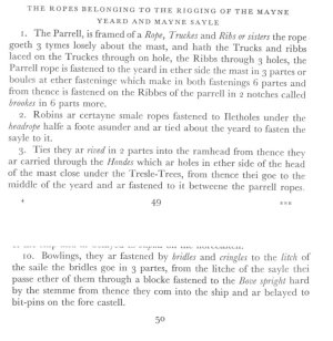
On my ship it will run along the main shroud of the fok. Through a chuck that is attached on the shroud to the jib and back. On the PW I will use a snatch-block on the foot of the Fok.
Maybe this info is a little help to you. (I used Peter Kirsch Die Galleonen for the rigging) but like I said, a little help, there is almost 200 years between both ships.
Edit.
It was Anderson on page 165 who discribes the lead of the bowline for ships like the Galleon and the PW.
Pictures say more then words.


Interresting part I discovered of the bowlines of a square rigger is that they are bring out as far as possible to the stem. Necessary to use the bowlines. I think that this fact never changed in the years. This is what I know about 17th century ships.
Treatise of rigging

Last edited:


