• Ships of Scale has incorportated an extra level of security when you log In. Please follow on-screen prompts to acknowledge that you are not a robot via a "Check Box" or a "Pictorial Check Box Puzzle". This is needed due to higher level of AI Activity Security.
  • SUBSCRIBE TO SHIPS IN SCALE TODAY!

    The beloved Ships in Scale Magazine is back and charting a new course for 2026!
    Discover new skills, new techniques, and new inspirations in every issue.

    NOTE THAT OUR NEXT ISSUE WILL BE July/August 2026
  • Win a Free Custom Engraved Brass Coin!!!
    As a way to introduce our brass coins to the community, we will raffle off a free coin during the month of August. Follow link ABOVE for instructions for entering.

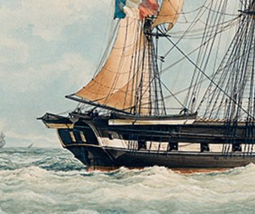
La Créole 1827 by archjofo - Scale 1/48 - French corvette

Many thanks, Steef, for your question.
I have not seriously considered writing a book, but your remark is a great compliment.
For now, I prefer to document the build step by step here in the forum.
Perhaps one day it will come to that.
In that case is your book almost ready. You have great pictures and the research. I did it for the "De Mofelbouwer" and it is fun to do, an extra chapter in your build experience. And I would buy it.
 
@dockattner
@Kurt Konrath
@Holger.Schwarz
@Hoss6262
Hi,
thanks a lot for the nice comments, and thanks also to everyone else for the likes.

Continuation: Running Rigging of the Main Yard – Les manœuvres courantes de grande vergue

When building my La Créole in 1:48 scale, the rigging of the running rigging is progressing as planned, from front to back and from bottom to top. The current focus is on the installation of the main yard and its associated running rigging.

View attachment 619479

In the meantime, the main yard sling has been secured using a flat seizing. The served ends of the truss rope were pulled through the sheaves in the trestletrees, thimbles were seized in, and the truss tackles were hooked into them and into the cap.

View attachment 619489

View attachment 619480

Next, I belayed the falls of the truss tackles to the pin rails on the bulwark. These lanyards run through so-called fairlead blocks (Moques de conduits) on the shrouds and via foot blocks to their belaying point, the belaying pins.
Furthermore, I was able to finally install and belay the lifts along with their tackles.

View attachment 619481

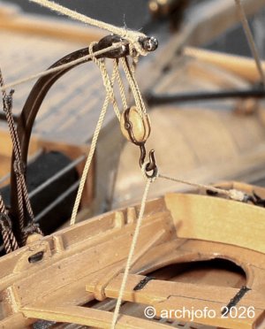
The following picture shows the double block with a swivel hook belonging to the starboard-side lift tackle.

View attachment 619486

After adjusting the lifts, the further equipping of the main yard continued.
Next on the agenda was the installation of the remaining running rigging for the main yard:
I dedicated myself to the leading of the clewlines (Cargues-points), as well as the buntlines (Cargues-fonds) and leechlines (Cargues-boulines). As mentioned several times before, I am rigging this model without sails; therefore, after being reeved through the corresponding yard blocks, these ropes were secured directly with a figure-eight knot (Achterknoten).

View attachment 619484

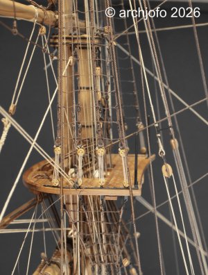
These lines were belayed at the mainmast using an iron spider band with belaying pins (Cercle à Cabillots), as can be seen in the next picture. It still looks a bit untidy there; for example, the main sheets are still loose, as they will only be fixed in conjunction with the topsail yards.

View attachment 619488

In this context, I would like to address a fundamental point that always plays a crucial role when rigging: for every running line, the path from top to bottom must be planned to be as collision-free as possible. It is often only after belaying that you realize a rope is overlapping another part or that an unintended contact occurs.
The lead through fairlead blocks and foot blocks down to the belaying point is particularly decisive. This is where it becomes clear whether a rope truly runs free or if it was accidentally routed over or under another part.

View attachment 619485

Consequently, I have already unreeved and rerouted individual lines several times until the run was correct.
The ideal path is always a lead that is as straight and undisturbed as possible from the yard through the blocks to the belaying pin—without crossings, without chafing points, and without unnecessary diversions. This fine-tuning takes time, but it ensures that the rigging is cleanly structured in the end and that the nautical logic of the era remains visible.

Finally, here is a picture showing the leading of the main brace at the starboard side of the stern: you can see the standing part and a large lead block attached to a wooden crossbeam. In the davit for the captain's gig, there are two sheaves: one for leading the main brace, while the other is reserved for leading the gaff vang, to which the single block also belongs.

View attachment 619487

To be continued…
my dear friend
I'm agree with Peter and Steef that,
This is indeed a first-rate masterpiece, worthy of a platform—such as a book—that honors your craftsmanship as a master artisan and serves future generations.
 
@Steef66
@shota70
Thank you very much, Shota — and once again, Stephan.
Your confidence in my work means a great deal to me.
I’m glad that the documentation of La Créole resonates so strongly with you that you would even consider it book‑worthy.
For now, I’ll continue presenting the build step by step here in the forum — but your words are truly a wonderful compliment.

And here we continue with a small update:

Continuation: Running rigging of the main yard – Missing lead block inside the bulwark
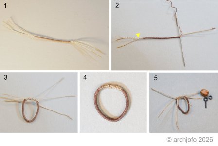
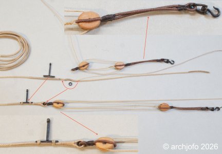
Not long ago, I reported on stropping the lead blocks inside the bulwark, more precisely along the waterways. While working on the running rigging of the main mast, I unfortunately discovered that one previously stropped double block was missing or had gone missing. The particular feature of these lead blocks is the strop, which is closed by means of a short splice. I therefore had to make another double block with short splice, thimble and eye bolt.

In itself this is no problem – only the memory of making those short splices is still rather unpleasant. Nevertheless, I had no choice but to revisit the subject. And indeed: it only took a small modification, and the short splices can be made much more easily and cleanly – something I did not want to keep from you.
Leitblock_Stropp_LaCreole.jpg

In contrast to my earlier method (image 1), I now tie off the ends a little before the served part of the strop (yellow arrow, image 2), and only the remaining portion is unlaid. This allows the strands to be passed one after another through the still‑intact section of the rope. Images 3 to 5 show the result.

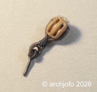
The last image shows the completed double block (block length 4.5 mm) with thimble and eye bolt.
DSC02720.jpg

This lead block was missing for the starboard topping lift of the main topsail yard.

More soon …

Johann
 
@dockattner
@Kurt Konrath
@Holger.Schwarz
@Hoss6262
Hi,
thanks a lot for the nice comments, and thanks also to everyone else for the likes.

Continuation: Running Rigging of the Main Yard – Les manœuvres courantes de grande vergue

When building my La Créole in 1:48 scale, the rigging of the running rigging is progressing as planned, from front to back and from bottom to top. The current focus is on the installation of the main yard and its associated running rigging.

View attachment 619479

In the meantime, the main yard sling has been secured using a flat seizing. The served ends of the truss rope were pulled through the sheaves in the trestletrees, thimbles were seized in, and the truss tackles were hooked into them and into the cap.

View attachment 619489

View attachment 619480

Next, I belayed the falls of the truss tackles to the pin rails on the bulwark. These lanyards run through so-called fairlead blocks (Moques de conduits) on the shrouds and via foot blocks to their belaying point, the belaying pins.
Furthermore, I was able to finally install and belay the lifts along with their tackles.

View attachment 619481

The following picture shows the double block with a swivel hook belonging to the starboard-side lift tackle.

View attachment 619486

After adjusting the lifts, the further equipping of the main yard continued.
Next on the agenda was the installation of the remaining running rigging for the main yard:
I dedicated myself to the leading of the clewlines (Cargues-points), as well as the buntlines (Cargues-fonds) and leechlines (Cargues-boulines). As mentioned several times before, I am rigging this model without sails; therefore, after being reeved through the corresponding yard blocks, these ropes were secured directly with a figure-eight knot (Achterknoten).

View attachment 619484

These lines were belayed at the mainmast using an iron spider band with belaying pins (Cercle à Cabillots), as can be seen in the next picture. It still looks a bit untidy there; for example, the main sheets are still loose, as they will only be fixed in conjunction with the topsail yards.

View attachment 619488

In this context, I would like to address a fundamental point that always plays a crucial role when rigging: for every running line, the path from top to bottom must be planned to be as collision-free as possible. It is often only after belaying that you realize a rope is overlapping another part or that an unintended contact occurs.
The lead through fairlead blocks and foot blocks down to the belaying point is particularly decisive. This is where it becomes clear whether a rope truly runs free or if it was accidentally routed over or under another part.

View attachment 619485

Consequently, I have already unreeved and rerouted individual lines several times until the run was correct.
Der ideale Weg ist stets eine möglichst gerade und ungestörte Führung von der Rahe über die Blöcke zum Belegnagel – ohne Kreuzungen, ohne Scheuerstellen und ohne unnötige Umwege. Diese Feinabstimmung braucht Zeit, gewährleistet aber letztendlich eine saubere Takelage und den Erhalt der nautischen Logik jener Zeit.

Abschließend sehen Sie hier ein Bild, das die Führung des Hauptseglers an Steuerbord des Hecks zeigt: Man erkennt den festen Teil und einen großen Bleiblock, der an einem hölzernen Querbalken befestigt ist. Im Davit für das Beiboot des Kapitäns befinden sich zwei Rollen: eine für die Führung des Hauptseglers, die andere für die Führung des Gaffelniederholers, zu dem auch der einzelne Block gehört.

View attachment 619487

Fortgesetzt werden…
Hallo Johann, was für hervorragende Detailfotos. Mir fällt auf, wie wunderschön du die (Kalben) gefertigt hast und mit Tuch versehen am Marstorp. Das ist ein sehr wichtiges Detail, welches viele Modellbauer während der Fertigung übersehen. Große Klasse Johann - Beste Grüße
 
@Holger.Schwarz
@GrantTyler

Many thanks to both of you for your interest and kind comments.
And many thanks to the others for the likes, too.


Iron Davits with Boat Hoisting Gear

Since I needed another "timeout" from rigging my French corvette, La Créole - as it can be quite tedious at times - I tried to clear up a question that was still wide open.

The rigging of the iron davits on La Créole:

A solved mystery between technological upheaval and historical reality.

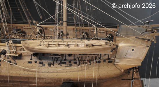
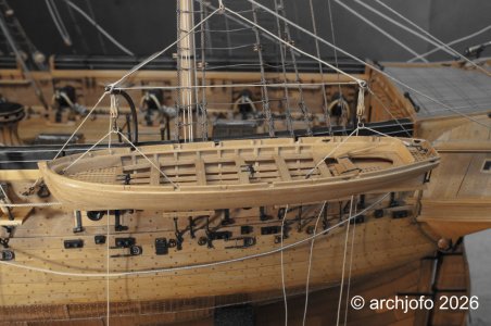
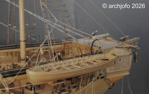
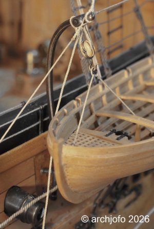
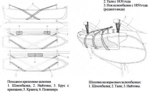
In the quarterdeck area, one encounters a small but fascinating detail: iron davits for the two smaller ship's boats (petits canots).

La Créole perfectly represents the era of early industrialization in France. While just shortly before, clumsy wooden derrick booms served as boat davits and dominated the view around the quarterdeck, technological progress now paved the way for highly modern designs. Thanks to the puddling process, which was developed in the late 18th century and by then well-established in France, a completely new material became available to the navy: wrought iron (puddled steel).

In contrast to brittle cast iron, this material was tougher, more flexible, and more resilient—the perfect prerequisite for manufacturing the elegantly curved, delicate iron davits, which I crafted from brass for my model and described a long time ago.

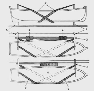
Jean Boudriot’s monograph leaves the practical ship modeler with a certain degree of ambiguity regarding the execution, particularly concerning the rigging of the boat davits. His interpretation of the rope lead raises questions that cannot be resolved beyond doubt based solely on his work.Only a targeted research in contemporary sources yielded the decisive results:

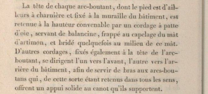
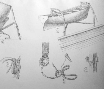
The system recorded in Frédéric-Albert Coste’s "Manuel de gréement" (1829) in the chapter "Installation et gréement des embarcations" starting on page 250 deviates from Boudriot’s description.

Screenshot 2026-07-27 213000.jpg

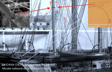
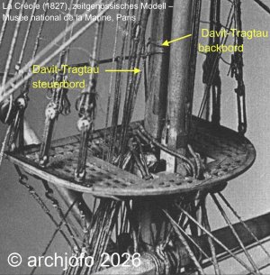
It states that the head of each davit (la tête de chaque arc-boutant), the foot of which is hinged to the ship's side, is held by a span rope. This rope functions as a topping lift, is bent on above the plaiting ( hounds) on the mizzen masttop, and is sometimes lashed down halfway up this mast.The most unbribable witness of this era ultimately proves that this description was by no means just gray theory: The original, contemporary shipyard model of La Créole in the Musée national de la Marine shows exactly this rigging arrangement, featuring a guy/hanging rope leading down from the masthead with a stropped thimble.

La_Créole_Bootsdavits.jpg

La_Créole_Bootsdavits_Belegung.jpg

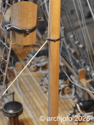
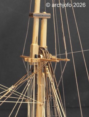
The entire immense tensile load of the boat davits along with the boats (totaling up to 1 ton in weight) is thus transferred via a rigidly fixed triangular geometry directly above the mizzen top platform into the massive lower mast. Technically, the ropes acted as permanently fixed davit pendants. A mast hoop with integrated rollers forces these ropes close to the mast shaft at about half the height of the lower mast. A detailed drawing in the Atlas des garnitures et des ferrements (1858) shows a comparable fitting - mechanically obvious, since the full weight of the boats must be redirected through these guy ropes with minimal friction.

This perfect match between the historical textbook and the original model not only resolves the contradiction found in the modern monograph.

In contrast, according to Boudriot's description, these guy ropes would be treated as running rigging, meant to be belayed on deck.For the final securing of the guy ropes to the mast, both the contemporary original model in the Musée national de la Marine and Coste’s description consistently show a wrapping around the mizzen masthead.

An explicitly labeled Atlas plate ("Agrès des Arcs-boutants d'embarcations", c. 1850) confirms the fundamental principle of French practice during this period; i.e., the davits were adjusted to the appropriate height once and permanently secured to the mast, presumably depending on the width of the boat.

Why the French forced the davit guy ropes close to the mast shaft by means of an iron ring with rollers is something I can only surmise as follows:

The boat weight represents a constant load that remains present during wind pressure on the sails or heeling, while at the same time one side of the shrouds slackens - a direct, robust binding into the mast shaft itself ensures that this load is more reliably absorbed further down the mast shaft, independent of the changing tension states of the shrouds.

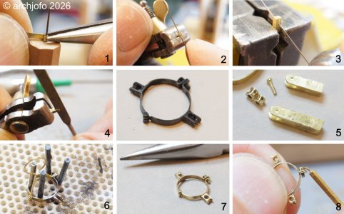
The following photo collage shows the individual steps of manufacturing the mast hoop.

LaCreole_Rigg_Bootdavits.jpg

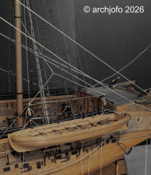
The actual lowering or hoisting of the boats was carried out exclusively via the separate boat tackles attached to the ends of the davit heads.For the model, I have fitted the entire arrangement on one side of the ship to see how it works. The final installation of the davits with the boats will not take place until the rigging of the mizzen mast is fully completed.

DSC02765.jpg

DSC02783.jpg

DSC02784.jpg

DSC02785.jpg

DSC02788.jpg

DSC02789.jpg

DSC02790.jpg

To be continued ...
 
@Holger.Schwarz
@GrantTyler

Many thanks to both of you for your interest and kind comments.
And many thanks to the others for the likes, too.


Iron Davits with Boat Hoisting Gear

Since I needed another "timeout" from rigging my French corvette, La Créole - as it can be quite tedious at times - I tried to clear up a question that was still wide open.

The rigging of the iron davits on La Créole:

A solved mystery between technological upheaval and historical reality.

In the quarterdeck area, one encounters a small but fascinating detail: iron davits for the two smaller ship's boats (petits canots).

La Créole perfectly represents the era of early industrialization in France. While just shortly before, clumsy wooden derrick booms served as boat davits and dominated the view around the quarterdeck, technological progress now paved the way for highly modern designs. Thanks to the puddling process, which was developed in the late 18th century and by then well-established in France, a completely new material became available to the navy: wrought iron (puddled steel).

In contrast to brittle cast iron, this material was tougher, more flexible, and more resilient—the perfect prerequisite for manufacturing the elegantly curved, delicate iron davits, which I crafted from brass for my model and described a long time ago.

Jean Boudriot’s monograph leaves the practical ship modeler with a certain degree of ambiguity regarding the execution, particularly concerning the rigging of the boat davits. His interpretation of the rope lead raises questions that cannot be resolved beyond doubt based solely on his work.Only a targeted research in contemporary sources yielded the decisive results:

The system recorded in Frédéric-Albert Coste’s "Manuel de gréement" (1829) in the chapter "Installation et gréement des embarcations" starting on page 250 deviates from Boudriot’s description.

View attachment 624741

It states that the head of each davit (la tête de chaque arc-boutant), the foot of which is hinged to the ship's side, is held by a span rope. This rope functions as a topping lift, is bent on above the plaiting ( hounds) on the mizzen masttop, and is sometimes lashed down halfway up this mast.The most unbribable witness of this era ultimately proves that this description was by no means just gray theory: The original, contemporary shipyard model of La Créole in the Musée national de la Marine shows exactly this rigging arrangement, featuring a guy/hanging rope leading down from the masthead with a stropped thimble.

View attachment 624739

View attachment 624740

The entire immense tensile load of the boat davits along with the boats (totaling up to 1 ton in weight) is thus transferred via a rigidly fixed triangular geometry directly above the mizzen top platform into the massive lower mast. Technically, the ropes acted as permanently fixed davit pendants. A mast hoop with integrated rollers forces these ropes close to the mast shaft at about half the height of the lower mast. A detailed drawing in the Atlas des garnitures et des ferrements (1858) shows a comparable fitting - mechanically obvious, since the full weight of the boats must be redirected through these guy ropes with minimal friction.

This perfect match between the historical textbook and the original model not only resolves the contradiction found in the modern monograph.

In contrast, according to Boudriot's description, these guy ropes would be treated as running rigging, meant to be belayed on deck.For the final securing of the guy ropes to the mast, both the contemporary original model in the Musée national de la Marine and Coste’s description consistently show a wrapping around the mizzen masthead.

An explicitly labeled Atlas plate ("Agrès des Arcs-boutants d'embarcations", c. 1850) confirms the fundamental principle of French practice during this period; i.e., the davits were adjusted to the appropriate height once and permanently secured to the mast, presumably depending on the width of the boat.

Why the French forced the davit guy ropes close to the mast shaft by means of an iron ring with rollers is something I can only surmise as follows:

The boat weight represents a constant load that remains present during wind pressure on the sails or heeling, while at the same time one side of the shrouds slackens - a direct, robust binding into the mast shaft itself ensures that this load is more reliably absorbed further down the mast shaft, independent of the changing tension states of the shrouds.

The following photo collage shows the individual steps of manufacturing the mast hoop.

View attachment 624738

The actual lowering or hoisting of the boats was carried out exclusively via the separate boat tackles attached to the ends of the davit heads.For the model, I have fitted the entire arrangement on one side of the ship to see how it works. The final installation of the davits with the boats will not take place until the rigging of the mizzen mast is fully completed.

View attachment 624731

View attachment 624732

View attachment 624733

View attachment 624734

View attachment 624735

View attachment 624736

View attachment 624737

To be continued ...

How a masthoop and the rigging of some davits becomes a peace of art! Very nice brass work and detailed rigging, Johann.
Regards, Peter
 
Dear Johann, the level of detail and insight in your work is outstanding (your research is historically sound, and your photos vividly illustrate the technical innovations of that transitional era). Your craftsmanship is not only fascinating but also inspires fellow modelers to approach their own builds with greater patience and dedication. I love your model and appreciate every new photo you share. For me, this represents a lasting record of the technology of that time—a history that absolutely deserves to be documented in both writing and photography. Best wishes and regards.
 
@KMSvideo
@Mirek
@Herman
@Peter Voogt
@Holger.Schwarz
@shota70
Hello,I would like to sincerely thank you for your interest in my work and for the kind comments. Of course, I also want to express my sincere thanks to everyone else for the likes.

@iutar
Hello,
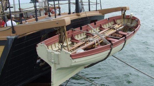
the images you provided showing the boat‑to‑davit attachments were extremely helpful.
I will refer to them again when I mount the boats after completing the rigging work.
Many thanks for your support.
 
Rigging the Main Topsail Yard - Vergue de grand hunier

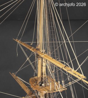
After a short excursion to the boat davits, I now proceed with the running rigging of my corvette.The largest yard (measuring approx. 48 cm, including the studdingsail booms) has now been fully rigged with its running gear.

In the next step, the main topsail yard was crossed. I brought it into position using the lifts beforehand, in order to subsequently rig the main topsail halyards.

The prepared main topsail halyards with the tye can be seen in the following picture.

DSC02726.jpg

The main topsail halyards, complete with their travellers (guides), were fully prepared and already bent to one end of the tye. After reeving the tye through the tye-blocks (one at the center of the topsail yard, two under the topgallant cross-trees), the other end of the tye could be connected to the halyard tackle on the opposite side of the model by splicing in a thimble (indicated by arrows). Attaching the main topsail halyard travellers, however, required opening the seizing of the main topmast backstays.

DSC02811.jpg

Finally, the main topsail halyards were hooked into eye-bolts on the channels using swivel hooks, and belayed on the inside of the bulwark.

The remaining rigging elements, such as the buntlines, leechlines, reef tackles, braces, and clewlines, were bent and belayed.

In principle, these work steps were identical to the installation of the fore yard and fore topsail yard. However, when belaying the running rigging at the mainmast, several lines coming from the foremast (the fore braces) had to be taken into account, and later on, a few ropes from the mizzenmast (bowlines, braces) will be added.

DSC02806.jpg

DSC02805.jpg

Until next time…
 
Seeing these ropes and details, who look almost like a real ship and not a model, I'm always amazing how you get them so straight and in the right direction. When I was rigging the Prins Willem my nineteenth nervous breakdown came along. These ropes always find another way to go then what you haved planned.
I love the details and the look of your ropes, your work is a true inspiration for us to follow.
 
Dear model shipbuilders, those of you who can pay such tribute to Johann’s craftsmanship through your appreciation and your own superb work in this style. Everything that has been written is so true and, above all, of such high calibre.
Best regards to you all, and to you, dear Johann: “fantastic”
 
Hello,
I would like to sincerely thank you for all your positive feedback. It means a lot to me to receive such appreciation from model builders whose own work I value and admire.

The level of detail, the care, and the craftsmanship you show in your models set a very high standard — which makes your recognition all the more meaningful to me.

I see this mutual respect as one of the finest aspects of our hobby: everyone contributes their strengths, everyone learns from one another, and together we reach a level that would be difficult to achieve alone.

Thank you all for your support and your encouraging words.
 
Back
Top