• SUBSCRIBE TO SHIPS IN SCALE TODAY!

    The beloved Ships in Scale Magazine is back and charting a new course for 2026!
    Discover new skills, new techniques, and new inspirations in every issue.

    NOTE THAT OUR NEXT ISSUE WILL BE July/August 2026
  • Win a Free Custom Engraved Brass Coin!!!
    As a way to introduce our brass coins to the community, we will raffle off a free coin during the month of August. Follow link ABOVE for instructions for entering.

La Créole 1827 by archjofo - Scale 1/48 - French corvette

@Kurt Konrath
@pugwash
@Holger.Schwarz
Thank you so much for your interest.
And thank you to everyone else for the likes!

Manufacturing Small Metal Cleats

Actually, the plan was to continue with rigging the main yard, since the sling on the yard are already in place and it is currently hanging on the model – secured only by the lifts. However, to keep motivation high, I like to insert other, varied tasks from time to time – especially since precise metalwork gives me particular pleasure.

My attention fell on a small but elegant detail in the stern area: horn cleats.

To belay the boom sheets, main braces, and boom tackles, I still need small cleats for my model of La Créole. In contrast to the large wooden cleats for the sheets and tacks of the fore and main mast, these small cleats were made of metal, as wood would not have provided the necessary strength.

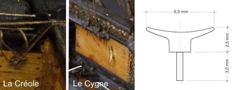
Since the monograph of La Créole contains no information on this detail, I tried to reconstruct these small cleats by studying photo excerpts of the original model and another model from the Musée national de la Marine, the brig Le Cygne (1806).
LaCreole_kleine_Klampen.jpg

By studying these photos, I was able to understand the shape and size of these cleats. It is also evident that these are metal cleats. In particular, the image of Le Cygne shows an elegant, crescent-shaped silhouette with curved horns – a horn cleat (taquet à cornes).

In model building, it is often speculated whether such delicate small parts were made of hardwood. From a shipbuilding perspective of the era around 1830, however, everything pointed to metal (bronze or iron), since the slender horns would have immediately splintered under the oblique pull of the stern lines along the wood grain.

This shipbuilding logic is supported by an absolute primary source of the period:

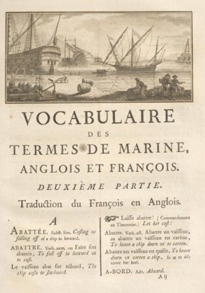
In the standard work Dictionnaire de marine à voiles by Baron Pierre-Marie-Joseph de Bonnefoux and François-Edmond Pâris (1847), this is explicitly described under the main term TAQUET on page 684 (following page 685).

Taking into account the standard sizes of cleats according to historical specifications (approx. 30 cm in the original), I chose a cleat length of about 6.5 mm for the model.

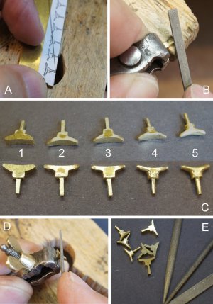
Since only a manageable number of cleats were needed, it was no major effort to make them by hand. I sawed them from a 1.5 mm thick brass plate, including a 3.0 mm long mounting pin, using a jeweler’s saw. The cleats were then shaped with various needle files, as shown in the following photo.
DSC02659.jpg

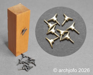
The mechanical work was completed with a fine intermediate and final manual sanding using sandpaper and the finest steel wool. The blackening gives them the authentic dark metallic character of iron.

The next two photos show the result and one already installed horn cleat.
DSC02660.jpg

DSC02661.jpg
More to come …
 
Johann,

Your attention to detail puts you in unique company, with those in the top of their field!

"A man's accomplishments in life are the cumulative effect of his attention to detail."
- John Foster Dulles...American Diplomat

"Details make perfection, and perfection is not a detail."
- Leonardo Da Vinci..Italian inventor, architect, artist, mathematician, scientist

"Success in any endeavor requires single-minded attention to detail and total concentration."
- Willie Sutton (aka, "Slick Willie,..famous bank robber

"My attention fell on a small but elegant detail in the stern area: horn cleats."
- Johann...researcher, artist, elite 20th century ship modeler

Thanks for sharing!
 
@dockattner
@Peter Voogt
@BradNSW
@Mirek
@KMSvideo

Hello,
Thanks a lot for the friendly comments and the LIKES — they give me extra motivation.
So let me continue with the next small update.

Continuation: Main tacks and sheets – Les amures et les écoutes de grande voile
Following my previous post on the lead and handling of the main tacks and sheets, I have now prepared the main tacks according to the authoritative French sources – in particular the Atlas du Génie Maritime and contemporary technical literature.
DSC02647.jpg

DSC02649.jpg

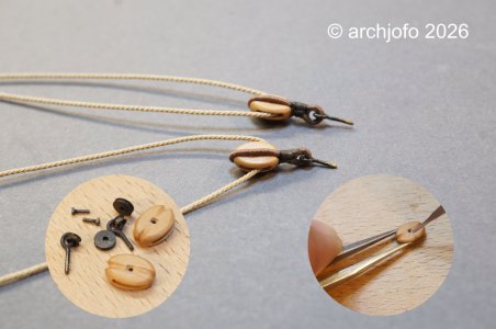
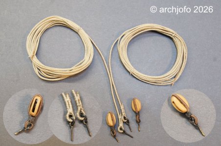
The two turning blocks, each 6.2 mm long, received their sheaves mounted on correctly made sheave pins. The block stroppings were fitted with thimbles and eye‑bolts for attachment to the deck.

The lines themselves are laid as thin cables (so‑called grelins), partly served on the standing parts, and already equipped with their thimbles and eye‑bolts for deck attachment.

More to come …
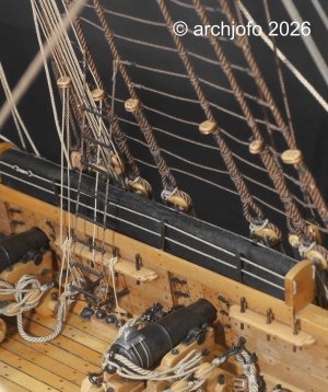
 
Continued: Mainsail Sheets and Tacks

In another forum, a post raised the following interesting question:

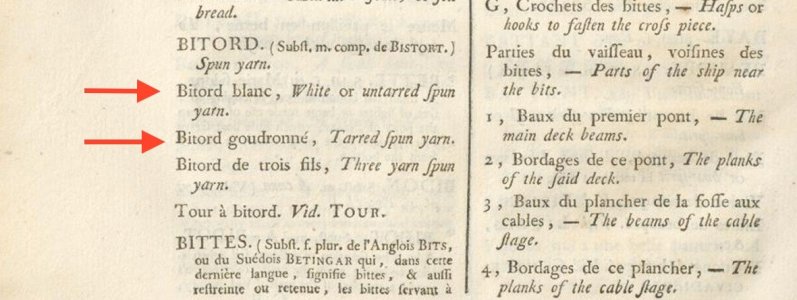
Why were the covered sections of the tacks and sheets of the mainsail and foresail covered with untarred spun yarn?

The light-coloured appearance of the served areas on the standing parts of the La Créole’s sheets and tacks is historically accurate for the French Navy around 1830.

The authoritative primary sources of the period draw a meticulous distinction between the materials used for serving:
While the rigid standing rigging was served dark and tarred (bitord goudronné), the chafe points of the running rigging were served exclusively with untarred spun yarn (bitord blanc).
The running rigging had to remain supple during manoeuvres; tarred yarn would have become too stiff.

Screenshot 2026-07-08 164829.jpg

Screenshot 2026-07-08 164750.jpg

These light zones were intended as sacrificial wear areas and are therefore shown on the La Créole model in the natural, pale tone of untarred spun yarn, exactly as historically documented.
 
@dockattner
@Peter Voogt
@BradNSW
@Mirek
@KMSvideo

Hello,
Thanks a lot for the friendly comments and the LIKES — they give me extra motivation.
So let me continue with the next small update.

Continuation: Main tacks and sheets – Les amures et les écoutes de grande voile
Following my previous post on the lead and handling of the main tacks and sheets, I have now prepared the main tacks according to the authoritative French sources – in particular the Atlas du Génie Maritime and contemporary technical literature.
View attachment 617452

View attachment 617453

The two turning blocks, each 6.2 mm long, received their sheaves mounted on correctly made sheave pins. The block stroppings were fitted with thimbles and eye‑bolts for attachment to the deck.

The lines themselves are laid as thin cables (so‑called grelins), partly served on the standing parts, and already equipped with their thimbles and eye‑bolts for deck attachment.

More to come …
Hi Johann. You show us what is possible in this hobby. Respect. Cheers Grant
 
@dockattner
@Peter Voogt
@BradNSW
@Mirek
@KMSvideo

Hallo,
Vielen Dank für die freundlichen Kommentare und die Likes – sie motivieren mich zusätzlich.
Dann möchte ich nun mit dem nächsten kleinen Update fortfahren.

Fortsetzung: Hauptnägel und Blätter – Les amures et les écoutes de grande voile
Nach meinem vorherigen Beitrag über das Führen und die Handhabung der Hauptnähte und Schoten habe ich nun die Hauptnähte gemäß den maßgeblichen französischen Quellen – insbesondere dem Atlas du Génie Maritime und der zeitgenössischen Fachliteratur – vorbereitet.
View attachment 617452

View attachment 617453

Die beiden Umlenkblöcke, jeweils 6,2 mm lang, erhielten ihre auf passgenauen Riemenscheibenbolzen montierten Seilscheiben. Die Blockverstrebungen wurden mit Kauschen und Ringschrauben zur Befestigung am Deck versehen.

Die Leinen selbst sind als dünne Kabel (sogenannte Grelins) verlegt, die teilweise an den stehenden Teilen befestigt sind und bereits mit Kauschen und Augbolzen zur Befestigung am Deck ausgestattet sind.

Fortsetzung folgt…
Hallo Johann, ich bin sehr begeistert von deiner Herangehensweise an die Detaillösungen. Jeder Modellbauer ist ja erst in der Lage, so anspruchsvoll zu fertigen, wie es seine übliche Entwicklung zulässt.
Das bedeutet, dass sich jeder in dieser Entwicklungszeit einräumt.
Du bist unglaublich präzise und es ist eine wirkliche Spiegelung der Realität. Für jeden Modellbauer inspirierend und möglicherweis auch bei genauer Betrachtung dieser hervorragenden Details eigener Anlass sich selbst beim fertigen eines Modells mehr Zeit zu geben.
Das insgesamt ist eine herausragende Leistung mit höchstem Anspruch. Beste Grüße Holger
 
@dockattner
@Kurt Konrath
@Holger.Schwarz
@Hoss6262
Hi,
thanks a lot for the nice comments, and thanks also to everyone else for the likes.

Continuation: Running Rigging of the Main Yard – Les manœuvres courantes de grande vergue

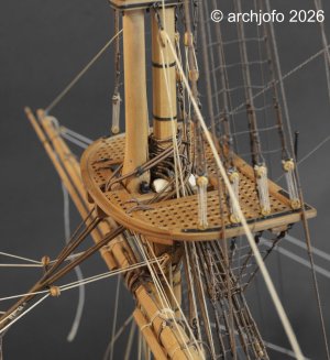
When building my La Créole in 1:48 scale, the rigging of the running rigging is progressing as planned, from front to back and from bottom to top. The current focus is on the installation of the main yard and its associated running rigging.

DSC02682.jpg

In the meantime, the main yard sling has been secured using a flat seizing. The served ends of the truss rope were pulled through the sheaves in the trestletrees, thimbles were seized in, and the truss tackles were hooked into them and into the cap.

DSC02707.jpg

DSC02692.jpg

Next, I belayed the falls of the truss tackles to the pin rails on the bulwark. These lanyards run through so-called fairlead blocks (Moques de conduits) on the shrouds and via foot blocks to their belaying point, the belaying pins.
Furthermore, I was able to finally install and belay the lifts along with their tackles.

DSC02695.jpg

The following picture shows the double block with a swivel hook belonging to the starboard-side lift tackle.

DSC02699.jpg

After adjusting the lifts, the further equipping of the main yard continued.
Next on the agenda was the installation of the remaining running rigging for the main yard:
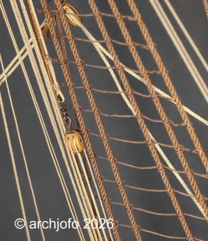
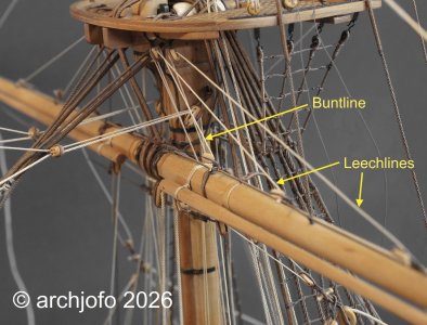
I dedicated myself to the leading of the clewlines (Cargues-points), as well as the buntlines (Cargues-fonds) and leechlines (Cargues-boulines). As mentioned several times before, I am rigging this model without sails; therefore, after being reeved through the corresponding yard blocks, these ropes were secured directly with a figure-eight knot (Achterknoten).

DSC02696a_engl.jpg

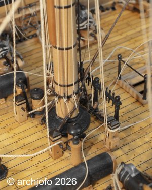
These lines were belayed at the mainmast using an iron spider band with belaying pins (Cercle à Cabillots), as can be seen in the next picture. It still looks a bit untidy there; for example, the main sheets are still loose, as they will only be fixed in conjunction with the topsail yards.

DSC02706.jpg

In this context, I would like to address a fundamental point that always plays a crucial role when rigging: for every running line, the path from top to bottom must be planned to be as collision-free as possible. It is often only after belaying that you realize a rope is overlapping another part or that an unintended contact occurs.
The lead through fairlead blocks and foot blocks down to the belaying point is particularly decisive. This is where it becomes clear whether a rope truly runs free or if it was accidentally routed over or under another part.

DSC02698.jpg

Consequently, I have already unreeved and rerouted individual lines several times until the run was correct.
The ideal path is always a lead that is as straight and undisturbed as possible from the yard through the blocks to the belaying pin—without crossings, without chafing points, and without unnecessary diversions. This fine-tuning takes time, but it ensures that the rigging is cleanly structured in the end and that the nautical logic of the era remains visible.

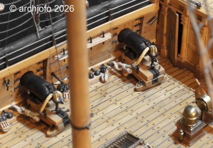
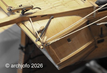
Finally, here is a picture showing the leading of the main brace at the starboard side of the stern: you can see the standing part and a large lead block attached to a wooden crossbeam. In the davit for the captain's gig, there are two sheaves: one for leading the main brace, while the other is reserved for leading the gaff vang, to which the single block also belongs.

DSC02705.jpg

To be continued…
 
@dockattner
@Kurt Konrath
@Holger.Schwarz
@Hoss6262
Hi,
thanks a lot for the nice comments, and thanks also to everyone else for the likes.

Continuation: Running Rigging of the Main Yard – Les manœuvres courantes de grande vergue

When building my La Créole in 1:48 scale, the rigging of the running rigging is progressing as planned, from front to back and from bottom to top. The current focus is on the installation of the main yard and its associated running rigging.

View attachment 619479

In the meantime, the main yard sling has been secured using a flat seizing. The served ends of the truss rope were pulled through the sheaves in the trestletrees, thimbles were seized in, and the truss tackles were hooked into them and into the cap.

View attachment 619489

View attachment 619480

Next, I belayed the falls of the truss tackles to the pin rails on the bulwark. These lanyards run through so-called fairlead blocks (Moques de conduits) on the shrouds and via foot blocks to their belaying point, the belaying pins.
Furthermore, I was able to finally install and belay the lifts along with their tackles.

View attachment 619481

The following picture shows the double block with a swivel hook belonging to the starboard-side lift tackle.

View attachment 619486

After adjusting the lifts, the further equipping of the main yard continued.
Next on the agenda was the installation of the remaining running rigging for the main yard:
I dedicated myself to the leading of the clewlines (Cargues-points), as well as the buntlines (Cargues-fonds) and leechlines (Cargues-boulines). As mentioned several times before, I am rigging this model without sails; therefore, after being reeved through the corresponding yard blocks, these ropes were secured directly with a figure-eight knot (Achterknoten).

View attachment 619484

These lines were belayed at the mainmast using an iron spider band with belaying pins (Cercle à Cabillots), as can be seen in the next picture. It still looks a bit untidy there; for example, the main sheets are still loose, as they will only be fixed in conjunction with the topsail yards.

View attachment 619488

In this context, I would like to address a fundamental point that always plays a crucial role when rigging: for every running line, the path from top to bottom must be planned to be as collision-free as possible. It is often only after belaying that you realize a rope is overlapping another part or that an unintended contact occurs.
The lead through fairlead blocks and foot blocks down to the belaying point is particularly decisive. This is where it becomes clear whether a rope truly runs free or if it was accidentally routed over or under another part.

View attachment 619485

Consequently, I have already unreeved and rerouted individual lines several times until the run was correct.
The ideal path is always a lead that is as straight and undisturbed as possible from the yard through the blocks to the belaying pin—without crossings, without chafing points, and without unnecessary diversions. This fine-tuning takes time, but it ensures that the rigging is cleanly structured in the end and that the nautical logic of the era remains visible.

Finally, here is a picture showing the leading of the main brace at the starboard side of the stern: you can see the standing part and a large lead block attached to a wooden crossbeam. In the davit for the captain's gig, there are two sheaves: one for leading the main brace, while the other is reserved for leading the gaff vang, to which the single block also belongs.

View attachment 619487

To be continued…
It's not just a model—it's a work of art. Congratulations. Frank
 
@dockattner
@Kurt Konrath
@Holger.Schwarz
@Hoss6262
Hi,
thanks a lot for the nice comments, and thanks also to everyone else for the likes.

Continuation: Running Rigging of the Main Yard – Les manœuvres courantes de grande vergue

When building my La Créole in 1:48 scale, the rigging of the running rigging is progressing as planned, from front to back and from bottom to top. The current focus is on the installation of the main yard and its associated running rigging.

View attachment 619479

In the meantime, the main yard sling has been secured using a flat seizing. The served ends of the truss rope were pulled through the sheaves in the trestletrees, thimbles were seized in, and the truss tackles were hooked into them and into the cap.

View attachment 619489

View attachment 619480

Next, I belayed the falls of the truss tackles to the pin rails on the bulwark. These lanyards run through so-called fairlead blocks (Moques de conduits) on the shrouds and via foot blocks to their belaying point, the belaying pins.
Furthermore, I was able to finally install and belay the lifts along with their tackles.

View attachment 619481

The following picture shows the double block with a swivel hook belonging to the starboard-side lift tackle.

View attachment 619486

After adjusting the lifts, the further equipping of the main yard continued.
Next on the agenda was the installation of the remaining running rigging for the main yard:
I dedicated myself to the leading of the clewlines (Cargues-points), as well as the buntlines (Cargues-fonds) and leechlines (Cargues-boulines). As mentioned several times before, I am rigging this model without sails; therefore, after being reeved through the corresponding yard blocks, these ropes were secured directly with a figure-eight knot (Achterknoten).

View attachment 619484

These lines were belayed at the mainmast using an iron spider band with belaying pins (Cercle à Cabillots), as can be seen in the next picture. It still looks a bit untidy there; for example, the main sheets are still loose, as they will only be fixed in conjunction with the topsail yards.

View attachment 619488

In this context, I would like to address a fundamental point that always plays a crucial role when rigging: for every running line, the path from top to bottom must be planned to be as collision-free as possible. It is often only after belaying that you realize a rope is overlapping another part or that an unintended contact occurs.
The lead through fairlead blocks and foot blocks down to the belaying point is particularly decisive. This is where it becomes clear whether a rope truly runs free or if it was accidentally routed over or under another part.

View attachment 619485

Consequently, I have already unreeved and rerouted individual lines several times until the run was correct.
Der ideale Weg ist stets eine möglichst gerade und ungestörte Führung von der Rahe über die Blöcke zum Belegnagel – ohne Kreuzungen, ohne Scheuerstellen und ohne unnötige Umwege. Diese Feinabstimmung braucht Zeit, gewährleistet aber letztendlich eine saubere Takelage und den Erhalt der nautischen Logik jener Zeit.

Abschließend sehen Sie hier ein Bild, das die Führung des Hauptseglers an Steuerbord des Hecks zeigt: Man erkennt den festen Teil und einen großen Bleiblock, der an einem hölzernen Querbalken befestigt ist. Im Davit für das Beiboot des Kapitäns befinden sich zwei Rollen: eine für die Führung des Hauptseglers, die andere für die Führung des Gaffelniederholers, zu dem auch der einzelne Block gehört.

View attachment 619487

Fortgesetzt werden…
Lieber Johann, es ist ein reines Vergnügen, das du uns an deiner unglaublichen Fertigung deines Ausnahmemodells teilhaben lässt.
Jedes Detail ist ein Meisterwerk „Es sollte unbedingt ein Fachbuch über den gesamten Entwicklungsverlauf deines kostbaren Schiffsmodells entstehen“. Das wäre ein geniales Betrachtungswerk.
Frohes schaffen und beste Grüße Holger
 
Back
Top