LA SALAMANDRE, bomb ketch - POF - (CAF-models, 1/48)

Due to the fact, that I am waiting for the spar jig, which will be hopefully send by Max in short time, I started with some frame work.
As I mentioned before the Salamandre is the first laser cut POF model, so I have to get used to the small but important specialities of this kind of wood / parts.
For a lot of you these info are well known, and you are used to work like this, nevertheless for some newcomers on such kit (like me) it is maybe for interest.

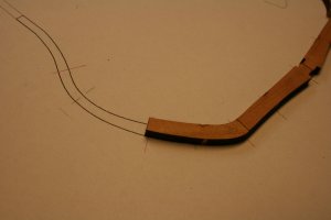
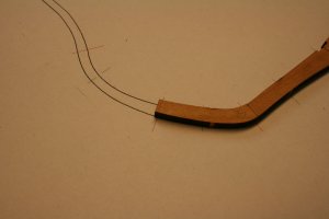
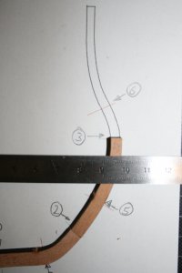
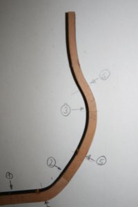
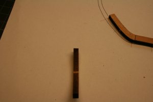
First of all I realized, that the laser cut is not in a 90° angle, means the gap which is burned by the laser has a v-shape, on the top side the gap is wider and at the deepest point the gap is very small. With this circumstance all the frame segments, futtocks etc. have no right angle. On the outer sides of the finished frames no problem, due to the fact that they will be sanded anyhow, but a small problem when two parts of the frame construction (f.e floor timber with first futtock) have to be glued together. So all the connection points of every futtock etc. have to be sanded to a 90° right angle.

One futtock with view from the side showing , that the sides are not in right angle
IMG_1632.JPG

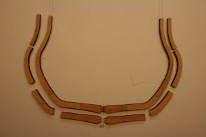
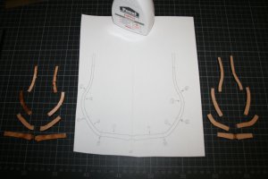
Here are the 15 parts for one frame (No. 13) not sanded and not prepared for glueing, so only the "raw material"
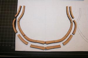
IMG_1622.JPG


I am using my Proxxon disk-sander to sand it to the correct right angle, so that the contact area between two futtocks are as big as possible and no gap between.
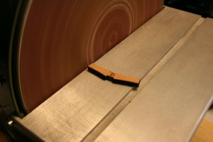
IMG_1624.JPG
 
The floor timber was prepared accurately and the joint between floor timber and first futtock (first red line) is correctly sanded.

IMG_1630.JPG

Usually than the futtocks are slightly longer, which you can compare with the second red line,
than I am marking with a knife the correct length

IMG_1631.JPG

and reduce the length once more with my disc sander. With the disc sander I am able to make realy right angles and also the shortening of the futtocks can be done very accurately to the correct length, so that the joints are realy overlaying with the given red and green lines of the frame plans.

Here you can see the elements of one frame prepared for gluing

IMG_1633.JPG
 
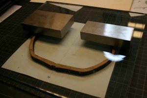
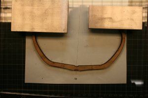
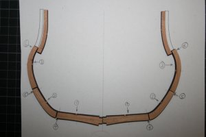
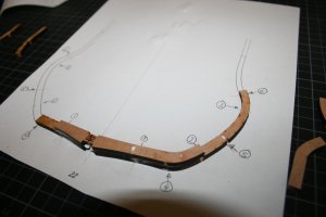
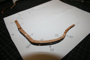
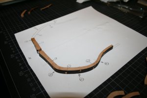
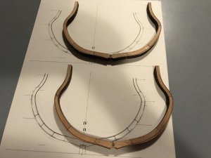
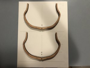
Here you can see a frame glued together. I am using a thick glass plate and put some heavy steel plates as additional weight.
With the glass plate I have the security, that it is very plane and distribute the weight equaly towards the frame........
usually over the floor timber is also one weight, I removed it only for the photo.

IMG_1626.JPGIMG_1627.JPG

......and you can see the frame if you want to see the glue drying ;)

So, now you know how I make the frames (in moment).....comments, hints what´s so ever are welcome
 
G'day Uwek
Your idea of using thick glass is BRILLIANT.
I'll be using that idea in the future, for sure!
:cool:
If you ask me, 'you're going great gun's', as the Ozzie expression goes.Keep up the great work, it's a tiresome and repetitive steps, I can imagine.
Havagooday mate
Greg
 
That’s great meticulous work Uwe. You are using far more precision for the joints than I am at this stage as I am finishing everything off by hand. I have to concede the gold standard for this build to you. I am using a similar method to set my ribs also. See my build which I am posting shortly. I may have to delay my build so you can get ahead and I then can follow.
 
Last edited:
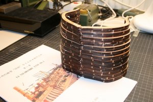
Nothing realy new today.......I am making every day 2 to 3 frames, depending how much time the normal job and my family is requesting.
So in this speed it will take some 2 weeks more until I have prepared them......until now 10 or 12 are made
BTW: Many many thanks to your friendly, encouraging posts and your likes of my posts.....
 
No clue in moment....have to think about when I am sitting in front of my kit.....will come back with some guess asap

sorry....still no clue....once you know something give me also a hint
 
Hi Uwe,

I don't often have time to get on and surf the boards and build logs, but must say it was a pleasant surprise to see you starting this build. The cross section in your avatar was an inspiration in my early days of modeling. :-)
 
Hi Uwe,

I don't often have time to get on and surf the boards and build logs, but must say it was a pleasant surprise to see you starting this build. The cross section in your avatar was an inspiration in my early days of modeling. :-)

Many thanks for your words. I am thinking about to show here the Triton cross section built in a short version with a lot of photos and some text. Unfortunately the old building log in MSW was lost over the years.....but the photos I still have......let us see
 
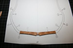
Frames, frames, frames.......a little bit boring, but it is good feeling to have some wood in hand and some woodglue at the fingers.
Maybe I am repeating somehow an older post, I hope it is not too boring for you if I show the cutting and also the glueing sequence in some more detail.
To show this it is hopefully helping somebody who made the first time such frames.....
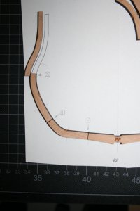
IMG_1654.JPG
First photo is showing the parts of the frame, originally out of the kit, with numbers 1, 2 and 3 are shown the parts which are too long and which should be shortened so that the parts are fitting to the joint marks (in red and green) shown on the drawing (here frame number 22)
The first part which has to be shortened is the floor timber at "1", afterwards the 1st futtock at "2" and at last "3", means working upwards.....

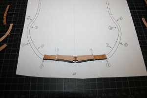
IMG_1655.JPG
With marks 4,5 and 6 the parts which have to be cutted on the second half of the frame.

IMG_1656.JPG
Both sides of the frame.....you can easily see, that the parts are all a little bit too long and are not fitting the drawing......But it is better that theay are too long and not too short ;)

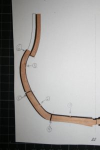
IMG_1657.JPG
Marking the cutting with a steel ruler and a sharb knife, sanding to the correct length.

IMG_1658.JPG
all parts on one side cutted to the correct length, so that the joints are correct at the red and green lines of the original drawings
 
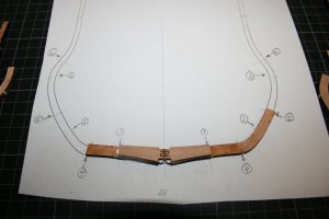
When I glue the parts together, I am also starting with the floor timer
IMG_1661.JPG

The second half of the floor
IMG_1662.JPG

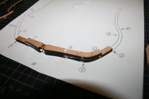
first futtock..... and so on up to the long and short top timber
IMG_1663.JPGIMG_1665.JPGIMG_1666.JPGIMG_1669.JPGIMG_1671.JPG

and the same on the other side

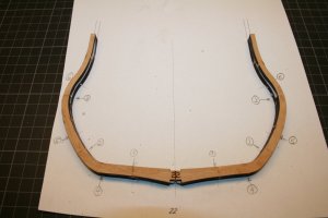
One more finished frame ..... ready for the "glass-plate"
IMG_1672.JPG
 
G'day Uwek
Re: post 34
I don't know that kit at all, but if I was you, I would check, double check and even triple check to see if I've got the CORRECT piece of timber before I would cut it to lenght.
I would even go to the point and emailing Max, if any one else have to cut some parts short.
I would put that frame a side and do another one.
Sorry if I'm butting in, but I would go through the entire laser cut pieces and placed each piece of every frame into a separate small zipper bag and Mark on each bag the frame number. ONLY THEN AFTER CHECKING EVERY PIECE 3 TIMES I WOULD CUT A PIECE.
Often, you can find 2 pieces labeled incorrectly or you might find that the piece some where else.
Just be careful when you do something drastic. I have learnt the hard way before and that's one lesson I'll never repeat.
That is why, my build log hasn't started yet. I'm going through the whole kit first and building it in my head and my computer.
Time is free, parts are not.
Havagooday
Greg
 
I sure hope the template drawings are correct size after printing.
Otherwise, you are doing a fabulous job of a kit that seems to be way out of accuracy.
It's a wonder that complaints have not withdrawn the kit.
 
I have been working the ribs a little different to Uwek. I am only using the green and red marks as guidelines and not cutting futtocks to them. Just hand sanding the char off the end of the futtocks. I have been mainly matching the ribs to the ANCRE plans. I have been getting a little extra “belly” on the kit drawings but a good match to the ANCRE drawings working this way. I am not sure if I am doing this correctly and maybe have problems later but the shape seems matching nicely to the ANCRE plans at this stage. Interesting learning experience working with ribs.BD3EAB36-31E1-4A61-9D82-ECB892DD2B85.jpeg97AACC39-186B-4421-A782-7CE0A788EDDC.jpeg
 
Last edited:
I have been working the ribs a little different to Uwek. I am only using the green and red marks as guidelines and not cutting futtocks to them. Just hand sanding the char off the end of the futtocks. I have been mainly matching the ribs to the ANCRE plans. I have been getting a little extra “belly” on the kit drawings but a good match to the ANCRE drawings working this way. I am not sure if I am doing this correctly and maybe have problems later but the shape seems matching nicely to the ANCRE plans at this stage. Interesting learning experience working with ribs.View attachment 35636View attachment 35637

I had a question about the Ancre plans. Do they show each and every frame drawing individually. Do the plans show enough views and such that I could build the model entirely from scratch if I wanted to?

Bob
 
Back
Top