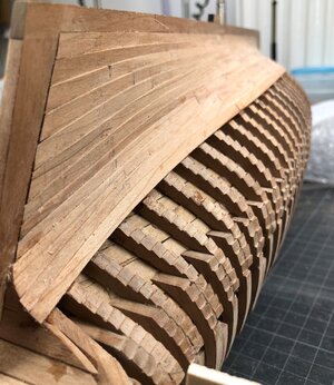
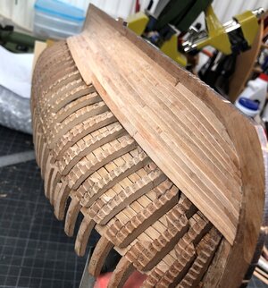
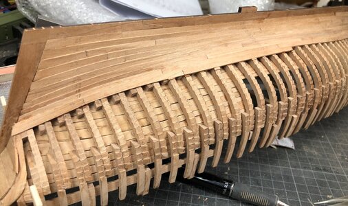
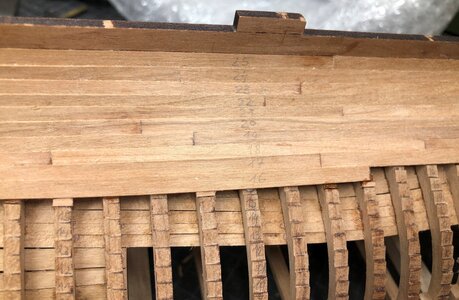
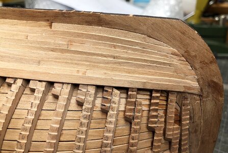
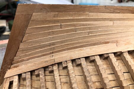
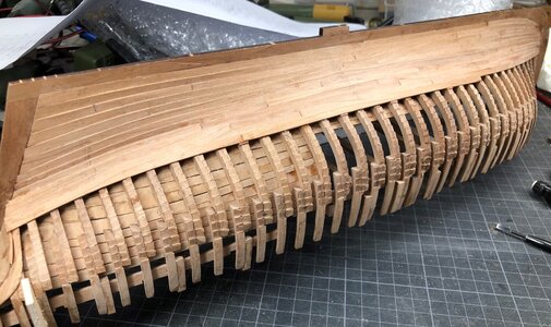
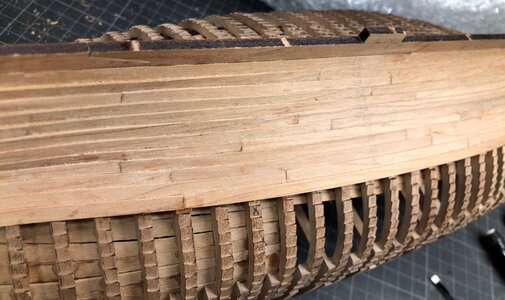
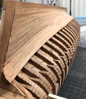
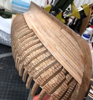
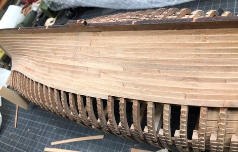
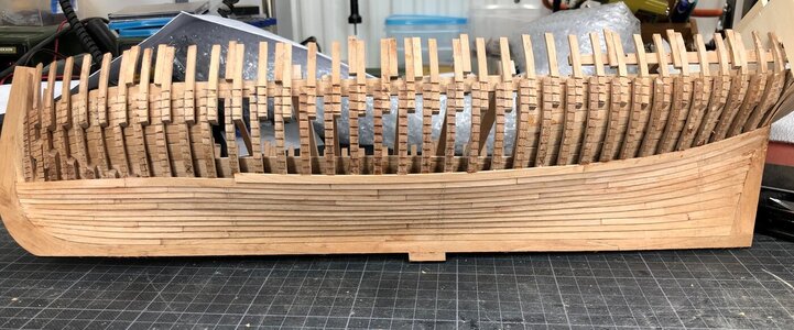
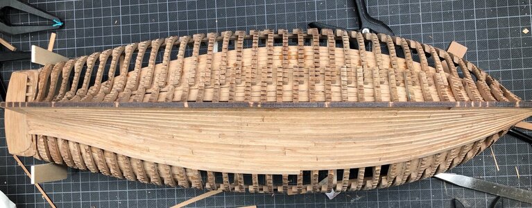
LE COUREUR - french Lugger 1776 - POF kit from CAF in 1:48 by Uwe

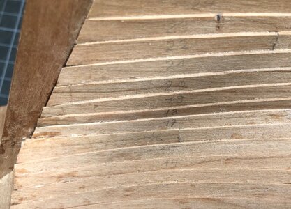
For the lower planks so far (22-25) that is easier said than done. Several of the planks require longitudinal twists, not mere bends.
In that case there is only one solution...
67F72366-91D5-4628-81AA-E0E499BAF2B8.jpeg

Happy ship building. I think I’ll focus on the interior and wait till after summer for the planking, not great in warm weather, the suit :)
 
Last edited by a moderator:
Dear Uwe,

I spent my evening reading your threat and I still have got the CAF (old SC) kit in my pile of kits. Due to your lines so I think I will join in here after the complete removal of my shipyard. So I will follow your kitbashing with high interest.

What I do not understand is who you do construct the new parts - from the paperplan's drawings or from the plywood pieces?

Thanks a lot for your interesting kind of writing and illustraiting.
 
What I do not understand is who you do construct the new parts - from the paperplan's drawings or from the plywood pieces?

Hallo Chris,
many thanks for your kind words.
Which new parts do you mean especially ?
 
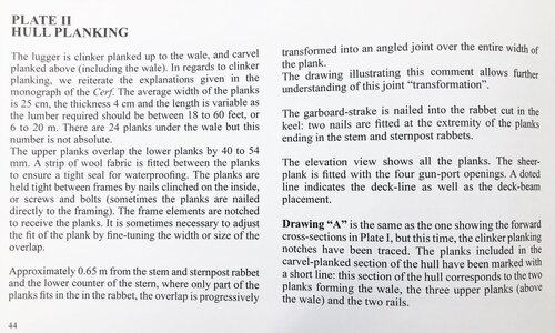
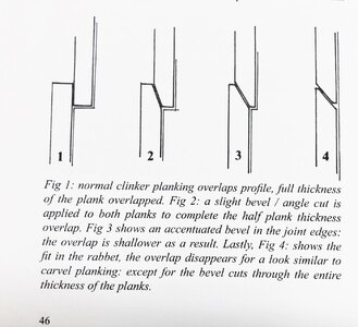
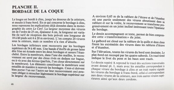
Here shortly the an excerpt of Jean Boudriot text he is writing in his book of the Le Coureur monographie about the planking

IMG-5375.jpg

IMG-5377.jpg

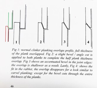
For myself and for this kit I adjusted slightly the clinker technique like shown in my sketch on the left side
IMG-5377a.jpg
The laser cut planks from the kit have in principle the cross section form like in Boudriots sketch under No. 1
The "red plank, is the plank which is installed next, the green one is the installed and already fixed plank.
I slightly cut a small edge, so that the wood glue have a little bit more meat - a long this edge I put a small volume of wood glue, so that both planks are connected and fixed
The red plank I usually sanded along the length, so that the visible edge is only appr. 50% of the thickness of the original plank - this is in my opinion more realistic
 

Attachments

  • IMG-5376.jpg
    IMG-5376.jpg
    250.9 KB · Views: 4
Looking really good. The clinker effect really adds dimension to the hull.
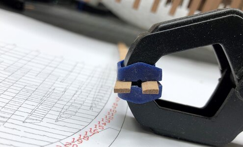
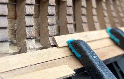
Are you still using CA glue and wood glue Uwe and is clamping still problematic?
 
Looking really good. The clinker effect really adds dimension to the hull.
Are you still using CA glue and wood glue Uwe and is clamping still problematic?
In the meantime the combination of CA and wood glue is my standard - and I did not try any other clamps.
It is working for me well, so I keep it

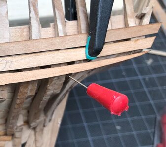
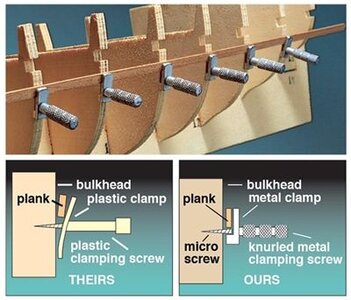
If you do not want to use CA glue, it is maybe a solution to cut such a needle much shorter.
IMG-5314a.jpg

pressing the needle into the frame (not through the plank, but next to the plank), so that the red plastic head is holding the plank at place.
stifte.jpg

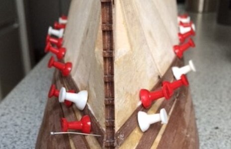
There are other needles in the market often used for Plank On Bulkhead kits. for the planking and installation pressing inside the bulkhead
57d9bf9cf567d43cfdc82ad67fee73e8--hms-victory-wooden-ship.jpg

The hole of the needle in the frame will be covered by the next row of planking
 
Here shortly the an excerpt of Jean Boudriot text he is writing in his book of the Le Coureur monographie about the planking

View attachment 204933

View attachment 204935

For myself and for this kit I adjusted slightly the clinker technique like shown in my sketch on the left side
View attachment 204936
The laser cut planks from the kit have in principle the cross section form like in Boudriots sketch under No. 1
The "red plank, is the plank which is installed next, the green one is the installed and already fixed plank.
I slightly cut a small edge, so that the wood glue have a little bit more meat - a long this edge I put a small volume of wood glue, so that both planks are connected and fixed
The red plank I usually sanded along the length, so that the visible edge is only appr. 50% of the thickness of the original plank - this is in my opinion more realistic
This photo I wanted also to show...... the cross section of every plank I prepare
IMG-5385.jpg

On the left side the "original" kit plank - on the right the sanded one with smaller "clinker edge surface"
 
I'm not sure I understand Uwe. Do you mean you are beveling the planks along the whole lenght of the ship? Doesn't that create some air space between the lower and the upper plank?:
1610381097526.png
Or are you reducing the height of the steps on the frames?

And do I understand correctly that you are not making a steadily increasing bevel over the last 1.4 cm before the stern post?
 
Last edited:
I'm not sure I understand Uwe. Do you mean you are beveling the planks along the whole lenght of the ship? Doesn't that create some air space between the lower and the upper plank?:
View attachment 205001
Or are you reducing the height of the steps on the frames?
@PoulD :
Do you mean you are beveling the planks along the whole lenght of the ship?
- YES
Doesn't that create some air space between the lower and the upper plank?:
- Maybe slightly on some smaller areas, but we are talking about micrometer - the same you have because of general inaccuracy of the modeler. In addition I try to make a very thin line of wood glue along the contact area of the two planks
Or are you reducing the height of the steps on the frames?
Not reducing, some adjustments of the depth are necessary, but more because of the small differences from frame to frame. I adjust the steps on the frames, so that the plank is laying smooth on the frames along the length of the plank

Additional info:
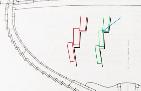
Very often the steps have less depth than the thickness of the plank (like shown on the left side in red)
So partly I deepen the step with a chisel and also I make the beveling the planks along the length (like at the middle green plank) - The main reason for this beveling is the fact, that a thinner plank (this part which is visible) fits better to the scale of the model!!!
Boudriot is writing, that the planks were only 4cm thick -> this is in scale 1:48 only 0,8mm !!! so thinner, than the planking material we have
cerf9aaa.jpg

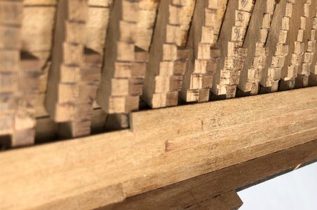
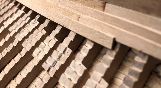
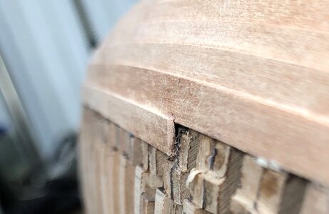
Here in the following also some excerpts from photos showing partly the ends of planks at butt joints which makes it hopefully more clear
IMG-5326a.jpg


IMG-5330a.jpg

IMG-5333a.jpg

IMG-5435a.jpg

Final summary:
At the end, every single plank element from the kit needs special treatment to get a good final result. The clinker planking needs everywhere some small adjustments to get a correct result. One plank element is passing and laying on top of maybe 10 or even 15 frames
But this is necessary, because no modeler will be able to make every single frame 100% correct, the height and alignment of every single frame on top of the keel by 100%, or also the steps on the frames - here some small errors or inaccuracies of the modeler (means myself) are multiplied
-> therefore every single part has to be checked, adjusted, sanded individually !!!! This means also, that I need per planking row (three or four parts) easily 3 to 5 hours, this means also per side of the hull it could be appr. 100 hours of fun making work !


 
And do I understand correctly that you are not making a steadily increasing bevel over the last 1.4 cm before the stern post?

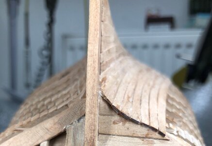
No - this is not necessary. The last length (why do you write exactly 1,4cm?) has to be flat and not beveled, due to the fact, that here the planks usually layed in clinker change into carvel planking. I am adjusting slightly the sanding in this transition zone by trying and dry fitting and trying and dry fitting until it is looking good enough. and when the complete planking of one side of the hull is finished, I have to give this the final correct sanding on the surface

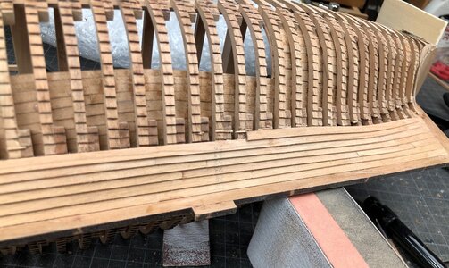
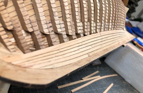
Here some photos of the status now, without the final touch work
IMG-5368.jpg

IMG-5371.jpg

IMG-5389a.jpg

IMG-5396a.jpg

IMG-5372.jpg
 
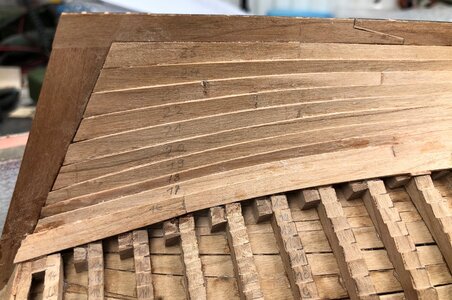
and here some "normal" photos of the progress of the planking works

IMG-5365.jpg

you can see here some additional small "blocks" at three locations so that plank 16 has a base - here seems to be, that I made in the earlier plank the overlapping to big and now I miss some one milimeter
IMG-5366.jpg

IMG-5367.jpg

IMG-5368.jpg

IMG-5369.jpg

IMG-5370.jpg

IMG-5371.jpg

IMG-5372.jpg

IMG-5379.jpg

IMG-5373.jpg

IMG-5374.jpg

IMG-5378.jpg
 
Many thanks Uwe, all clear now . And I must say your clinker planking looks very good indeed Thumbsup

Here I thought the inner planking was a lot of slow, troublesome back-breaking work. Now I understand the old fart is up for something even worse once I get so far as to the outside planking :eek:

Why did I write 1.4 cm? From Boudriot's text: "Aproximately 0.65 meter from the stem and sternpost the overlap is progressively transformed into an angled joint". (65 cm in 1:48 = 1.35 cm)
 
@PoulD :
Do you mean you are beveling the planks along the whole lenght of the ship?
- YES
Doesn't that create some air space between the lower and the upper plank?:
- Maybe slightly on some smaller areas, but we are talking about micrometer - the same you have because of general inaccuracy of the modeler. In addition I try to make a very thin line of wood glue along the contact area of the two planks
Or are you reducing the height of the steps on the frames?
Not reducing, some adjustments of the depth are necessary, but more because of the small differences from frame to frame. I adjust the steps on the frames, so that the plank is laying smooth on the frames along the length of the plank

Additional info:
Very often the steps have less depth than the thickness of the plank (like shown on the left side in red)
So partly I deepen the step with a chisel and also I make the beveling the planks along the length (like at the middle green plank) - The main reason for this beveling is the fact, that a thinner plank (this part which is visible) fits better to the scale of the model!!!
Boudriot is writing, that the planks were only 4cm thick -> this is in scale 1:48 only 0,8mm !!! so thinner, than the planking material we have
View attachment 205122

Here in the following also some excerpts from photos showing partly the ends of planks at butt joints which makes it hopefully more clear
View attachment 205124


View attachment 205125

View attachment 205126

View attachment 205127

Final summary:
At the end, every single plank element from the kit needs special treatment to get a good final result. The clinker planking needs everywhere some small adjustments to get a correct result. One plank element is passing and laying on top of maybe 10 or even 15 frames
But this is necessary, because no modeler will be able to make every single frame 100% correct, the height and alignment of every single frame on top of the keel by 100%, or also the steps on the frames - here some small errors or inaccuracies of the modeler (means myself) are multiplied
-> therefore every single part has to be checked, adjusted, sanded individually !!!! This means also, that I need per planking row (three or four parts) easily 3 to 5 hours, this means also per side of the hull it could be appr. 100 hours of fun making work !
"Fun making work..." I like that one Uwe. This is a hobby after all!
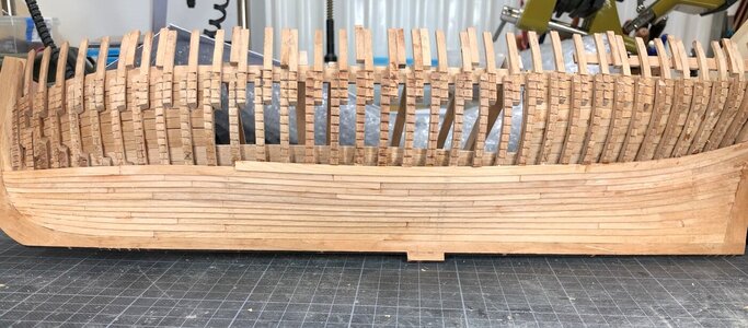
 
Looking very nice! I have also found that each row of planks is quite time consuming, moreso as my eye grows more discerning :)
 
Very nice Uwe. Clinker building is far more complex then regular carvel building. I will have to deal with it on my alert also :)
On the Alert, it will be also very interesting, due to the fact, that the frames have not these steps, so you have to plan the planking more in advance.
I am looking forward to see your work

For everybody interested, please take a look at Maartens amazing work on the Alert in his building log:
 
Back
Top